1
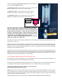
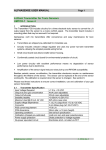
Operating Instructions
100mm [SPU] Low Pressure Natural Gas Purge Unit
This purge unit is designed for the direct purging of pipework up to 100 mm bore from air to natural gas. It can
also be used for natural gas to air purging but an air mover must be used which is available as an optional extra
item. Larger Purge Units for above 100 mm bore pipework are also available, contact GEA for information.
The unit can also be used for setting up meter regulators under flow conditions.
All Soundness Testing and Purging must be carried out as set down in IGEM publications UP/1, or UP/1A if
the volume is less than 1 cubic metre [35.3 cubic feet] and the operating pressure is below 40 mbar.
The Unit is mounted in a vinyl coated wooden and aluminium framed box that should be stable under
reasonable conditions on a firm base. The box is not intended to be left outside for long periods and should be
stored in the dry.
A valved test point is included for the connection of a Gas Analyser such as a Gascoseeker. The flow meter
measures the gas velocity at a flow as given in UP/1A and can be used for low pressure purging of pipework
up to and including 100mm [4"] bore.
No Smoking signs are attached to the box and it may be wise to use a red/white Barrier Tape to keep people
more than 5 metres from the Purge Unit, which must be located in a safe place. Always keep a fire
extinguisher handy.
Assembly:
The door must be opened out to give the box stability. The length of hose should be carefully removed from
the box and connected to the union at the lower right hand side of the box and to the installation pipework. Do
not over-tighten these unions as they achieve gas tightness quite easily if not damaged. Additional lengths of
hose are available.
Remove the four plastic vent uprights from the door clips. Unscrew the flame trap from the 1" socket in the
base of the box and screw in by hand to the top part of the vent stack. Screw the four pieces together and screw
in by hand into the connection on the 'top' of the box. The flame trap is now over 2.5m above ground level.
Operation:
The direct gas to air or air to gas purge operation is detailed in IGEM UP/1 and UP/1A.
Check the connections and hose are in good condition.
Attach the Danger sign to the inlet purge valve.
Verify that the pipe size to the purge connection is large enough to provide the purge flow rate without excess
pressure drops. If the meter sizes are correct and the purge rate cannot be obtained, the pipe to the purge point
is too small. If possible, move the purge connection to a larger section of pipe and purge to that point before
finishing the purge on the original smaller pipe. If this is not practicable, a purge with nitrogen according
to UP/1 must be carried out.
For correct purging to The Institution of Gas Engineers and Managers (IGEM) UP/1, 1A an optimum flow rate
is required, this and can be easily set by the 1" full bore manual valve inside the Purge Unit
Global Energy Associates Ltd, St John’s, Dunmow Road, Bishops Stortford CM22 6SP
A flow rate of below 3 cubic metres per hour will be adequate for
pipe sizes below 50mm [2"] bore
For 50 mm [2"] bore set the control valve to give a flow of 4.5
m3/h. The primary meter must be U6 rating or larger.
For 80 mm [3"] bore set the control valve to give a flow of
11 m3/h. The primary meter must be U16 rating or larger.
For 100 mm [4"] bore set the control valve to give a flow of
20 m3/h. The primary meter must be at least U16 rating.
Set flow
rate here
The purge gases may be tested with a methane gas analyser
after 15 seconds of flow. The purge should be completed after a
time in seconds equal to about 1.5 to 3 times the full length of
the pipe plus any installed ‘U’ meter and hose in metres. For
example, a 25m length of pipe, U16 meter [20m equiv] and the
5m of purge hose should purge in about 75 to 150 seconds at the
correct flow rate for the largest pipe being purged.
Where a ‘U’ meter is installed add 20m for U16 & 25, 30m for
U40 & 60, and 35m for U100 & 160.
The methane analyser should register around 90% at the completion of the purge, depending in the exact
characteristics of the gas.
During the purge to gas, the flow rate may change. This is normal and is caused by the change in specific
gravity as the flow of air is replaced by the lighter gas. This flow is above that necessary but speeds the purge
operation. Conversely, when purging from gas to air, the flow will change and must be adjusted upwards to
maintain the ideal minimum velocity.
It should not be necessary with this design of unit to monitor the gas pressure during purging since the
indication of the correct flow on the meter shows that adequate pressure exists. Please note that if an electronic
gauge is used it must be intrinsically safe if used in flammable environments. Do not forget to have any test
instrumentation checked and calibrated at least annually.
Never attempt to light the purge gases on the Flame Trap.
On completion of a successful purge to gas, you should have achieved at least 90% methane. Higher levels
may not be possible due to the constituents of the gas itself.
When removing redundant pipework and gas meters it is essential to purge to air and to get less than 40% LFL
or more than 20.5% oxygen. An optional airflow mover is available for use in gas to air purges.
All removed components must be capped or sealed correctly.
Open ended pipework must not be left.
Finally, replace the vent pipes in their clips in the box. Expose the disconnected Purge Hose to the open air
for several minutes to vent out the gas and then carefully wind the Purge Hose into the box. If it is extremely
cold, the Hose may be too stiff to safely get back inside without damage to the box. Replace the flame trap
onto its 1" socket in the base of the box.
Global Energy Associates Ltd, St John’s, Dunmow Road, Bishops Stortford CM22 6SP