1
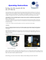
Operating Instructions
Fan Purge Unit- 240 volt model [APU 150]
and [APU 200] Units
These Fan Purge Units are designed for the direct purging of pipework from natural gas to air. They are is
intended to be used in conjunction with the Purge Units with integral meters to set the optimum flow
velocity required by The Institution of gas Engineers and Managers (IGEM) UP1 and 1A which are
available as an optional extra item. These units can also be used to pressurize pipework for testing.
All Soundness Testing and Purging must be carried out as set down in Institution of Gas Engineers
publications UP/1, or UP/1A if the volume is less than 1 cubic metre [35.3 cubic feet] and the pressure is
below 75 mbar [30 in wg].
The fan unit is mounted in a vinyl coated wooden and aluminium framed box that should be stable under
reasonable conditions on a firm base. The box is not intended to be left outside for long periods and should
be stored in the dry.
A check valve is fitted as a protection against reverse flow of gas into the fan assembly.
Assembly:
Place the Fan Purge Unit in the open air in a safe and dry location. Open the door and remove the length of
hose/hose coupling from the box and connect it to the installation pipe or meter assembly at an appropriate
valved point.
Ensure this valve is closed. Then connect the hose to the connection on the side of the box. Do not overtighten the fittings as they achieve air tightness quite easily if not damaged. Additional lengths of hose are
available from GEA.
Do NOT use the unit inside a meter room unless the room has been tested and proven to be free of gas.
Previous Model APU
Current APU 150 and APUM 200
Always visually check the connecting cable and plug before use. Fit an RCD main electricity supply protector
before the fan or any extension lead when using 240V. If you have any doubt about the electrical safety of the
cables, fan or RCD, consult a qualified electrician.
Global Energy Associates Ltd, St John’s, Dunmow Road, Bishops Stortford CM22 6SP
Operation:
The direct gas to air purge operation is detailed in IGE UP1 and UP/1A.
When purging pipework, verify that the pipe size to the purge connection is large enough to provide the purge flow
rate without excess pressure drops. If the meter sizes are correct and the purge rate cannot be obtained, the pipe to
the purge hose point is too small. If possible, move the purge connection to a larger section of pipe and purge to
that point before finishing the purge on the original smaller pipe. If this is not practicable, a purge with nitrogen
according to UP/1 must be carried out.
The following procedure must be followed in order to prevent the reverse flow of gas back into the fan purge
unit.
With the connecting valve to the Fan Purge Unit closed, depressurise the installation pipework or meter installation
through the Purge vent pipe. Check the gas pressure within the pipework to ensure the pressure has dropped to
atmospheric.
Turn on the Power to start the fan and open the valve at the end of the fan hose to admit air into the system.
Open the Purge Valve at the base of the vent pipe and adjust to give the correct flow rate as required by UP/1 or
UP/1A. When the gas concentration has reduced at the test point to give less than 40% LFL or more than 20.5%
oxygen, the purge may be considered to be complete. Testing of gases must be with calibrated instrumentation in
accordance with the manufacturer’s instructions.
Where items such as meters are being purged prior to transportation, it is suggested that the purge should be
continued until about 10% LFL has been achieved.
Close all valves and turn off the Power, disconnecting the lead, any extension cable and any RCD. Disconnect the
hose.
All removed pipe components, meters and controls must be capped or sealed correctly.
Installation pipework must not be left open ended.
Finally, replace the hose and supply cable in the box.
Special Note:
Purging meters after removal for a Gas Transporter.
In this instance, the meter is to be purged without being connected to any installation pipework, e.g. on return to
stores. The same basic use of the Fan Purge Unit and vent stack applies. The purge rate must not at any time cause
the meter to over-speed. To achieve this, the pressure difference between the inlet and outlet of the meter should not
exceed 1 mbar if the meter is not to be scrapped, measured by inlet and outlet meter pressure tappings, and
controlled by a meter outlet valve. The purge end points remain as stated above. The outlet connection from the
meter should always be vented to a safe open air location away from all sources of ignition.
Global Energy Associates Ltd, St John’s, Dunmow Road, Bishops Stortford CM22 6SP