1
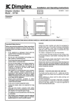
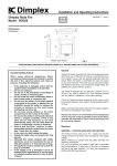
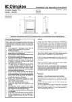
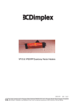
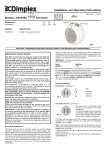
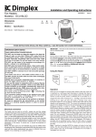
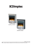
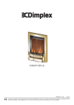
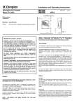
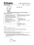
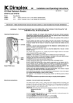
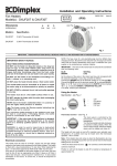
Installation and Operating Instructions
Brayford Log Stove
Springborne Coal Stove
Model: BFD20
Model: SBN20
440
08/18740/3
295
547
440
Issue 3
295
547
controls
Brayford
controls
Springborne
Model: BFD20
Model: SBN20
Fig. 1
IMPORTANT : THESE INSTRUCTIONS SHOULD BE READ CAREFULLY AND RETAINED FOR FUTURE REFERENCE
General
Important Safety Advice:
When using electrical appliances, basic precautions
should be followed to reduce the risk of fire, electric
shock, and injury to persons, including the following :
•
If the appliance is damaged, check immediately
with the supplier before installation and operation.
•
Do not use this heater in the immediate
surroundings of a bath, shower or swimming pool.
•
Do not use outdoors.
•
This heater must not be located immediately below
a fixed socket outlet or connection box.
•
Do not cover or obstruct in any way the heat outlet
grille located at the bottom of the heater.
Overheating will result if the heater is accidentally
covered.
•
Unpack the heater carefully and retain the packaging for possible
future use, in the event of moving or returning the fire to your
supplier.
This model is designed to be free standing and is normally
positioned against a wall.
A choice of 1kW or 2kW heat output is provided by the fan heater,
which is located at the bottom of the unit.
Before connecting the heater check that the supply voltage is the
same as that stated on the heater.
On the Springborne model loose coals are packed separately within
the carton. When the heater is assembled the coals can be placed
on top of the fuel bed, as required.
Please note: Used in an environment where background noise
is very low, it may be possible to hear a sound which is related
to the operation of the flame effect. This is normal and should
not be a cause for concern.
Electrical
Ensure that furniture, curtains or other
combustible materials are positioned no closer
than 1 metre from the heater.
WARNING: THIS APPLIANCE MUST BE EARTHED.
•
In the event of a fault unplug the heater.
•
Unplug the heater when not required for long
periods.
•
Keep supply cord away from the front of the
heater.
•
Although this heater complies with safety
standards, we do not recommend its use on deep
pile carpets or on long hair type of rugs.
In the event of replacing the fuse supplied, a 13 amp fuse approved
by ASTA to BS 1362 must be used.
If the socket outlets in your home are not of the 13 amp BS1363
type they will not accept the plug connected to this heater, therefore
cut off the plug. When cut off this plug can constitute a shock
hazard if inserted into a socket outlet. It must therefore be disposed
of safely.
Before wiring the appropriate plug please note that the wires in this
mains lead are coloured in accordance with the following code.
•
This appliance is not intended for use by children
or other persons without assistance or
supervision if their physical, sensory or mental
capabilities prevent them from using it safely.
Children should be supervised to ensure that they
do not play with the appliance.
This fire is suitable for operation on an AC~ electricity supply having
the same voltage as that shown on its rating label.
GREEN/YELLOW BLUE BROWN -
EARTH
NEUTRAL
LIVE
Connect the Green/Yellow wire to the terminal marked ‘E’ or the earth symbol
coloured Green or Green/Yellow.
Connect the Brown wire to the terminal marked ‘L’ or coloured Red.
Connect the Blue wire to the terminal marked ‘N’ or coloured Black.
or
•
The appliance must be positioned so that the plug
is accessible.
DO NOT connect the Brown (Live) or the Blue (Neutral) wires to the
Earth terminal of your 13 amp plug. If the terminals of the plug are
unmarked or you are in any doubt, consult a qualified electrician.
•
If the supply cord is damaged it must be replaced
by the manufacturer or service agent or similarly
qualified person in order to avoid a hazard.
CAUTION: If you use this heater in conjunction with a thermal
control, programme controller, timer or any other device which
switches the heater on automatically observe all safety warnings at
all times.
Operation
The unique flame effect may be enjoyed whether or not the heating
elements are in operation.
Controls
The heater controls are located on the right hand side of the fan
heater. (see Fig 1)
Three switches provide a choice of heat settings. A switch is in the
ON position when the side with the markings on (i.e. I , I , or II ) is
pushed in.
Fig. 4
To gain access to the lamps, the four screws which secure the back
panel, must be removed. Remove and slide out panel as indicated
on Fig. 4
Fig. 2
Switch 1 ( I )
Controls the electricity supply to the heater and
flame effect.
Note: This switch must be in the ON
( I ) position for heater to operate with or without
heat.
Switch 2 ( I )
Provides 1kW heat output
Switch 3 ( II )
Provides 2kW output with switch 2
Remove the defective lamp by unscrewing it as shown - see Fig. 5.
Replace with a 60W E14 SES Clear Candle lamp.
Take care not to over-tighten the lamp. Refit the back panel and
secure with the four screws.
Safety cut-out
Maintenance
WARNING –
Fig. 5
BEFORE UNDERTAKING ANY MAINTENANCE
OR CLEANING REMOVE PLUG OR
DISCONNECT FROM THE ELECTRICITY
SUPPLY.
An automatic cut-out will switch off the heater if for any reason it
overheats. This could occur for instance, if the air inlet or outlet were
restricted in any way. If the cut-out operates, the heater will switch
off. The heater will switch on once the obstruction has been
removed and the heater has cooled. If the cut-out continues to
operate intermittently, the heater should be switched off and
Customer Services contacted.
Cleaning
Lamp Replacement
For general cleaning use a soft clean duster – never use abrasive
cleaners. The plastic viewing screen should be cleaned carefully
with a soft cloth. DO NOT use proprietary glass cleaners.
After Sales Service
Your product is guaranteed for one year from the date of purchase.
Within this period, we undertake to repair or exchange this product
free of charge (excluding lamps & subject to availability) provided it
has been installed and operated in accordance with these
instructions.
Your rights under this guarantee are additional to your statutory
rights, which in turn are not affected by this guarantee.
Fig. 3
Two lamps are located behind the back panel as indicated in Fig.3.
Should you require after sales service you should contact our
customer services help desk on 0870 727 0101. It would assist us if
you can quote the model number, series, date of purchase, and
nature of the fault at the time of your call. The customer services
help desk will also be able to advise you should you need to
purchase any spares.
Please do not return a faulty product to us in the first instance as this
may result in loss or damage and delay in providing you with a
satisfactory service.
Please retain your receipt as proof of purchase.
The product complies with the European Safety Standards EN60335-2-30 and the European Standard Electromagnetic Compatibility
(EMC) EN55014, EN60555-2 and EN60555-3 which cover the essential requirements of EEC Directives 73/23 and 89/336
Glen Dimplex UK Limited
Millbrook House
Grange Drive
Hedge End
Southampton
Hampshire. SO30 2DF
UK customer help line (8.00AM – 6.00PM Mon-Fri; 8.30AM-1.00PM Sat)
Customer Services:
Republic of Ireland
Tel.
Fax.
e-mail
Tel.
0870 7270101
0870 7270102
[email protected]
01 8424833
[c] Glen Dimplex UK Limited
All rights reserved. Material contained in this publication may not be reproduced in whole or in part, without prior permission in writing of Glen Dimplex UK Limited.