1
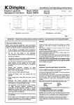
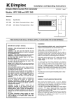
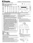
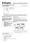
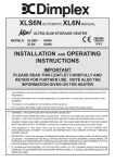
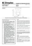
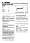
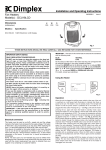
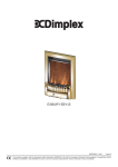
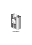
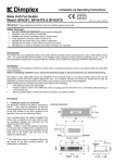
VALENCIA
08/19355/2
Issue 2
The product complies with the European Safety Standards EN60335-2-30 and the European Standard Electromagnetic Compatibility
(EMC) EN55014, EN60555-2 and EN60555-3 which cover the essential requirements of EEC Directives 73/23 and 89/336
1
639
618
‘x’
205
700
157
B
‘y’
655
617
632
A
C
‘z’
2
648
550
‘a’
632
567
668
75
165 Min.
3
4
5
+
-
6
O
F
F
O
N
‘a’
7
‘x’
8
‘y’
TABLE OF CONTENTS
1.
FOREWORD
1
2.
INTRODUCTION
1
3.
SAFETY PRECAUTIONS
1
4.
INSTALLATION
2
4.1 Installation Instructions
2
4.2 Installation Space
2
4.3 Location and Minimum Free Space
2
4.4 Recessed Installation
2
OPERATION
2
5.0 Operation
2
5.1 Initializing the remote control
2
5.2 Remote control operation
3
5.3 Manual operation
3
5.4 Thermal safety cut
3
CLEANING AND MAINTENANCE
3
6.1 Cleaning
3
6.2 Lamp replacement
3
AFTER SALES SERVICE
4
5.
6.
7.
-1-
1.
UK
FOREWORD
This fire incorporates a flame effect which can be used with or without heating, so that comforting effect may be
enjoyed at any time of the year. The flame effect is provided by a low wattage motor and three 60 watt lamps. Using the
flame effect on its own, therefore, requires little electricity.
The controls are located at the bottom right hand corner of the appliance (see ‘z’ in Fig 1). A choice of 750W or 1500W
heat output is provided by the fan heater, which is concealed at the top of the heater (see ‘x’ in Fig 1) behind the
removable front panel (see ‘y’ in Fig 1).
The Valencia is designed to be inset in a fireplace opening.
2.
INTRODUCTION
This instruction manual gives you information about the design, operation and maintenance of your fire, as well as
safety precautions and environmental recommendations.
As you read this manual, you will quickly learn how to operate your fire. You will also find information about the safety
and maintenance of the equipment.
Read the manual carefully before using your fire and then keep the manual in a safe place.
3. SAFETY PRECAUTIONS
•
Have the stove installed by a qualified installer in accordance with local and national (fire safety)
regulations.
•
Ensure that all packaging items are removed (read any warning labels carefully).
•
Retain all packaging until installation is complete.
•
The heater must be used on an ~ 230V supply and the voltage marked on the heater must correspond
with the supply voltage.
•
Warning: This appliance must be earthed.
•
When using electrical appliances, basic precautions should always be followed to reduce the risk of
fire, electrical shock, and injury to persons, including the following:
•
If the appliance is damaged, check immediately with the supplier before installation and operation.
•
Do not use outdoors,
•
Do not use in the immediate surroundings of a bath shower or swimming pool.
•
Do not locate the heater immediately below a fixed socket outlet or connection box.
•
Do not cover the heater. Do not place material or garments on the heater, or obstruct the air circulation
around the heater, for instance by curtains or furniture, as this could cause overheating and a fire risk.
•
Do not leave young children unsupervised in the vicinity of the heater.
•
Ensure that furniture, curtains or other combustible material are positioned no closer than 1 meter
from the heater.
•
In the event of a fault unplug the heater.
•
Although the heater complies with safety standards, we do not recommend its use on deep pile
carpets or on long hair type of rugs.
•
The appliance must be positioned so that the plug is accessible.
•
If the supply cord is damaged it must be replaced by the manufacturer or service agent or similarly
qualified person in order to avoid a hazard.
-2-
UK
4. INSTALLATION
4.1 INSTALLATION INSTRUCTIONS
Have the stove installed by a qualified installer in conformance with national and local (fire safety) regulations.
Be sure that the chimney functions properly.
4.2 INSTALLATION SPACE (see Fig. 1)
A:
B:
C:
Adjustable Feet
Recommended built-in height
Connection cable
4.3 LOCATION AND MINIMUM FREE SPACE
Before installing read all safety warnings and operating instructions.
At the base of the fire, four adjustable feet (see ‘A’ in Fig. 1) are provided for levelling the fire where the base of the
fireplace opening is raised above the level of the hearth.
Adjust by turning the feet until the desired height has been reached.
The fire is designed to be inset in a fireplace opening - see ‘Recessed Installation’ and Fig. 2 for details.
4.4 RECESSED INSTALLATION
In order to ensure it’s future safety in use, it is essential that this fire is securely fixed to the wall.
IT IS IMPORTANT THAT THE FIXING DEVICE CHOSEN IS APPROPRIATE TO THE WALL MATERIAL TO WHICH
THE FIRE IS BEING FIXED. SOME MODERN INTERNAL BUILDING MATERIALS ARE VERY LOW DENSITY
BLOCK AND REQUIRE SPECIALIZED FIXING DEVICES TO PROVIDE A SAFE,SECURE INSTALLATION.
The installation of this fire should be carried out by a competent person.
Follow steps as outlined below :
1.
Make sure that the fire is located on a flat surface.
2.
In existing fireplaces seal all draughts and vents to prevent chimney debris from falling onto the fireplace insert.
Do not install into an existing fireplace that is prone to dampness.
3.
Remove the fire front panel - see ‘6.2 Lamp Replacement’ and Fig. 7.
4.
Locate the 4 fixing holes, position the fire accordingly, and firmly fix the appliance to the wall using the appropriate
screws - see ‘a’ in Fig. 2 for hole fixing dimensions and recommended recess size.
5.
Replace the front panel.
If you intend to build a purpose built structure/hearth please use the recommended dimensions as indicated in Fig. 2
If in doubt of any of the above please consult your local builder.
5. OPERATION
5.0 OPERATION
The controls are located at the bottom right hand corner of the appliance - see ‘z’ in Fig. 1.
Connect the fire to your electricity supply.
Note: When either the remote control or the manual controls are used the neon’s will come on for 3 seconds indicating
the appropriate setting - see Fig. 3.
5.1 INITIALIZING THE REMOTE CONTROL
Note: The remote control is packed separately in the carton.
1.
Slide open the battery cover on the back of the remote transmitter.
2.
Install the AAA batteries into the remote control (see Fig. 4).
3.
Replace battery cover.
DISCARD LEAKY BATTERIES
Dispose of batteries in the proper manner according to Provincial and local regulations. Any battery may leak electrolyte
if mixed with a different battery type, if inserted incorrectly, if all the batteries are not replaced at the same time, if
disposed of in a fire or if an attempt is made to charge a battery not intended to be recharged.
-3-
UK
5.2 REMOTE CONTROL OPERATION
Warning: It takes some time for the receiver to respond to the transmitter. Do not press the buttons more than once
within two seconds for correct operation.
Operation
Setting
Operation
Indication
Flame effect
Flame effect & 750W heat setting
Flame effect & 1500W heat setting
Press the ‘I’ button once
Press the ‘I’ button again
Press the ‘I’ button again
Left Neon
Left & Middle Neon
All 3 neon’s
To turn off any of the settings press the ‘O’ button once.
To increase or decrease the brightness of the fuel effect use the buttons ( ) as shown in Fig. 5.
5.3 MANUAL OPERATION
Note: The Standby Switch (see ‘a’ in Fig. 6) must be first turned on to operate either the manual or the remote controls.
The red indicator mark on the switch will be visible when it is turned on.
Setting
Operation
Indication
Flame effect
Flame effect & 750W heat setting
Flame effect & 1500W heat setting
Press the ‘I’ button once
Press the ‘I’ button again
Press the ‘I’ button again
Left Neon
Left & Middle Neon
All 3 neon’s
To turn off any of the settings press the ‘O’ button once.
To increase or decrease the brightness of the fuel effect use the buttons ( ) as shown in Fig. 6.
5.4 THERMAL SAFETY CUT-OUT
For your safety, this appliance has been fitted with thermal cut-out. In the event that the product overheats, the cut-out
switches the heat off automatically.
To bring the heat back into operation, remove the cause of the overheating, then unplug or turn off the electrical supply
to the heater for up to 10 minutes.
When the heater has cooled sufficiently, re-connect and switch on the heater.
6. CLEANING AND MAINTENANCE
Warning:
Always disconnect from the power supply before attempting any maintenance.
6.1 CLEANING
Before commencing cleaning, unplug the heater and allow it to cool.
The surface of the heater should be given an occasional wipe over with a soft damp cloth. Do not use detergents
abrasive cleaning powder or polish on the body of the heater. The glass screen should be cleaned carefully with a
chamois leather. Do not use proprietary glass cleaners.
6.2 LAMP REPLACEMENT
To gain access to the lamps.
1.
Remove the front frame (see ‘x’ in Fig. 7) by lifting out then up and carefully leave to one side.
2.
Remove the three screws (see ‘y’ in Fig. 7) on the fuel effect.
3.
Slide the fuel effect out, by holding the front ledge and set aside carefully (taking care not to damage the logs as
they are fragile) – see Fig. 7.
4.
For access to the bulbs, carefully rotate the flexible rotisserie out of position ensuring that the rubber grommet is
not lost – see Fig. 8.
5.
Unscrew the defective lamp anti-clockwise. Replace with a 230V, 60W E14 SES lamp, do not over tighten (see
Fig. 8).
6.
Refit the fuel effect (with three screws) and Front Panel.
-4-
7.
After Sales Service
Your product is guaranteed for one year from the date of purchase.
Within this period, we undertake to repair or exchange this product free of charge (excluding lamps & subject to
availability) provided it has been installed and operated in accordance with these instructions.
Your rights under this guarantee are additional to your statutory rights, which in turn are not affected by this guarantee.
Should you require after sales service you should contact our customer services help desk on 0870 727 0101. It would
assist us if you can quote the model number, series, date of purchase, and nature of the fault at the time of your call.
The customer services help desk will also be able to advise you should you need to purchase any spares.
Please do not return a faulty product to us in the first instance as this may result in loss or damage and delay in
providing you with a satisfactory service.
Please retain your receipt as proof of purchase.
Glen Dimplex UK Limited
Millbrook House
Grange Drive
Hedge End
Southampton
Hampshire. SO30 2DF
UK customer help line (8.00AM – 6.00PM Mon-Fri; 8.30AM-1.00PM Sat)
Customer Services:
Republic of Ireland
Tel.
Fax.
e-mail
Tel.
0870 7270101
0870 7270102
[email protected]
01 8424833
[c] Glen Dimplex UK Limited
All rights reserved. Material contained in this publication may not be reproduced in whole or in part, without prior permission in writing of Glen Dimplex UK Limited.