1
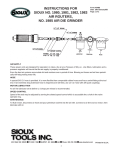
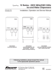
Contents Specifications 2 Features 3 Keypad functions 3 Operating Instructions 4 power switch 4 syringe diameter entry 5 volume entry 5 rate setting 6 power failure mode 6 rate and volume changes while running 7 fast forward 7 Syringe loading 8 Stall settings, microliter syringe precautions 9 NV Ram Failure 10 Fuses 10 Maintenance 10 Syringe Table 11 Table of Maximum and Minimum Flow rates 12 Warranty 13 SPECIFICATIONS Model - model 100 series, including KDS100, 101 and 120 Syringe size - 10 microliter to 60 milliliter Electrical Rating - US model 115V~, 0.1A Fuse - 5x20 mm, 250V~ slow blow CE model 230V~, 0.05A 0.1A with 115 Volt ; 0.5A with 230Volt supply Voltage operating range - US model 110-130V~, 50/60Hz CE model 220-260 V~,50/60Hz Drive mechanism - microprocessor controlled stepper gearmotor (_ microcrostepping), driving a leadscrew through a belt and pulley drive mechanism Pusher advance per half step - 0.529 micron or 2.083x10⁻⁵ inch (KDS100) - 0.088 micron (KDS101) Linear Travel - KDS100, KDS120 - minimum 0.00635 cm/hr; maximum 76.18 cm/hr KDS101 - minimum 0.00106 cm/hr; maximum 12.2 cm/hr Minimum stepping rate - one _ step in thirty seconds Ð may vary depending on syringe size Maximum stepping rate - 400 _ steps / second Speed range - 12000:1 Flowrate range - 0.1ul/hr (10 ul syringe) to 506ml/hr (60 ml syringe) Linear force - 20 lb min. ( 9 Kgm) Dimensions - 9x6x5 inch (23x15.25x13 cm) Weight - 5 lb (2 Kgm) Atmospheric Specifications Temperature Humidity : : -40 to +85 Degrees C L.T. 95% Mode of Operation : Continuous Classification : Class I Pollution Degree : 2 Installation Category : II Output : N/A Physiological Effects : N/A Cooling Conditions : No special considerations Mechanical Stability : No special considerations Protective Packaging : No special considerations Earth Terminals : No External connections required Removable Protective Means : N/A Supplier Name : KD Scientific Inc. Address : 3307 Windy Bush Rd, New Hope, PA 18938, USA 2 FEATURES The Model 100 series are simple, accurate cost effective syringe pumps designed to hold glass or plastic syringes, of any make, from 10 microliter to 60 milliliter for the KDS100; 10 ul to 15 ml for the KDS120; and 10 ul to 10 ml for the KDS101. The models KDS100 and KDS101 are infusion only pumps. The flow rates of the KDS101 and six times slower than that of the KDS100 and the units of flow rate are suitably adjusted. The KDS120 is a push-pull infusion/simultaneous withdrawal pump. Setup and pump operation for all the 100 series pumps are similar and extremely simple. A menu, displayed on an alphanumeric LCD "prompts" the operator to make the necessary selections using the keypad for choice of features and numerical entries. The internal diameter of the syringe is used by the control program to calibrate the pump and deliver the volume and flowrate selected. For simplicity the syringe diameter is also used to set automatically the volume and flowrate units. The syringe diameter can be entered directly or the syringe can be identified from a table of syringes held in memory. When the syringe is selected from the table the diameter is entered automatically. Two dispense modes are available: a) dispense volume mode in which the pump keeps track of the volume dispensed and automatically stops the pump when a set target volume is reached. b) run mode where the pump runs at the set flowrate until manuallystopped. In the event of a power interruption during operation, the pump can be programmed to either resume operation or remain stopped when power is returned. For convenience, all pump settings are stored in non-volatile memory to minimize the number of setting changes required. 1) KEYPAD FUNCTIONS å This key has two functions: a. Moves the display to the left b. Causes the numerical entry to decrease. To change the displayed number by a single unit press and release the key quickly. If the key is pressed longer the number changes with increasing speed. ä This key has two functions. a. Moves the display to the right b. Causes the numerical entry to increase. To change the displayed number by a single unit press and release the key quickly. If the key is pressed longer the number changes with increasing speed. 3 select This key has three functions: a. b. c. run/stop a. b. 2) Return to main menu when pressed repeatedly Selects the pulsing or "highlighted" feature of the main menu display. Enter numerical values. Turns the motor on and off. Acts as a "pause" during a dispense. DISPLAY After the pump is programmed an arrow on the right side of the display indicates the direction of operation. This arrow pulses when the pump is running. 3) OPERATING INSTRUCTIONS POWER SWITCH The power switch is located at the right, rear corner of the pump. When the power is turned on the LCD will display the Volume or Rate setting. Press the select key to return to the main menu. MAIN MENU Pressing select repeatedly will always return the display to the main menu. The main menu consists of five variables, three of which are displayed at all times. The center variable pulses to indicate that this option can be reviewed or changed. The menu acts as a continuous loop and the arrow keys, å ä are used to move around the loop. The variable to be changed can be selected with the select key. ← - - - → dia ← - - - →table ← - - - → rate ←- - - → vol ←- - - → pwr up ← - - - → direct entry syr dia (mm) syr dia. mfr, size flowrate ul or ml/h dispense vol ul or ml 4 run/stop SYRINGE DIAMETER ENTRY For automatic internal calibration the syringe diameter must be entered. Once entered the diameter is retained in non-volatile memory and need not be entered again unless the syringe used is changed. When a syringe diameter is changed the Volume and Rate settings are set to zero. There are two methods of diameter entry. a. Internal library Select TABLE from the main line menu. The table of syringes is organized by manufacturer, then by glass or plastic, and then by size. Use the arrow keys to scroll through the table and the select key to enter the correct setting. First, scroll through the manufacturers and select the manufacturer of the syringe used. The menu will next display either syringe type or syringe size. Again, use the arrow keys to move through the table until the correct size is displayed. Press the select key when the correct syringe size is displayed. This automatically enters the internal syringe diameter. See Table 1 for the syringe library. b. Direct entry From the main menu select DIA. The display will read "xx.xx mm". Use the arrow keys to display the measured internal diameter of the syringe in millimeters and enter with the select key. Changing the diameter clears the Volume and Rate settings, and the display will now prompt for the new Volume setting. VOLUME ENTRY The Volume setting mode is selected from the main menu or is displayed automatically after changing the diameter. Display reads: xx.xx ul (Units ul or ml depend on syringe diameter entered) 1) Use the arrow keys to enter the dispense volume required. 2) When the correct dispense volume is displayed enter this number with the select key. note: If no target dispense volume is required enter volume = 0.0 The pump will run at the set flowrate until stopped manually or a stall occurs. 3) After setting a Volume the menu prompts for the flowrate setting. When the pump runs the actual dispensed volume will be displayed and will increment until the set volume is reached, at which time the pump will stop automatically. FLOWRATE ENTRY 5 RATE can be selected from the main menu or will be displayed automatically after the Volume setting. The display reads: Rate: X.X ul/h or X.X ml/h Rate units are ul/h or ml/h, microliter or milliliter/hour and are selected automatically from the syringe diameter. 1) 2) 3) Use the arrow keys to display the flowrate required. Enter the rate with the select key. If the rate entered is out of range, a message is displayed: " Max Rate XX ml/h" To continue enter a lower rate ,or select a larger syringe. note: a. If a dispense volume was set then the display will now change to "Volume : 0.0" ,that is, in automatic dispense mode. When the pump runs the actual dispensed volume will be displayed and will increment until the set volume is reached, at which time the pump will stop automatically. b. If no dispense volume is set the LCD displays the set flowrate and, when running, the directional indicator arrow will pulse. START THE PUMP a. Press the run/stop key to start the pump. A second press will stop the pump. b. If the pump is stopped during a dispense the volume accumulator is not cleared - the dispense is paused. Restarting the pump with a second press of the run/stop key continues the dispense to the target volume. POWER FAILURE MODE If there is a temporary power interruption, when no dispense volume is selected, the Power Up run/stop option allows the pump to either resume the dispense when the power returns, or remain stopped but display a message warning of the power failure. 1) Move the main menu to the right and select PWR UP. 2) The display will read Power Up Run ( or STOP ). Use the arrow keys to change display and select the required option Run After power is returned the pump resumes normal operation. The display flashes PowerFailed to acknowledge a power interruption. Press Select to display the Rate. STOP Pump does not run when power returns. The LCD displays the rate setting. If a dispense volume is entered the power interruption stops the pump, clears the volume accumulator and returns the volume to the setpoint. Only if the power failure setting is ÒrunÓ will the power failure warning be displayed. CHANGE OR REVIEW VOLUME SETTING WHILE RUNNING 6 While the pump is running it is possible to look at the volume and flowrate settings without interrupting the operation of the pump. If required the volume and flowrate settings can be changed while the pump continues to run. When the changes are entered the pump immediately changes to the new settings. 1) While operating press select to return to the main menu. 2) Select Volume to display the set dispense volume. If no change is required press select 3) For a volume change use the arrow keys and enter with the select key. 4) The display moves to RATE, permitting a change if required. Press select if no change is required. or Use the arrow keys to change the setting. The select key immmediately changes to the new flowrate and the volume display continues to increment, uninterrupted to the new dispense setting. note: If the VOLUME is changed to a setting smaller than the volume already accumulated then the pump stops when the new, smaller dispense volume is selected. CHANGE OR REVIEW RATE SETTING WHILE RUNNING 1) Press select to change the volume accumulator display to the main menu. 2) Select RATE. 3) Make rate changes if required and press select. The pump immediately changes to the new flow rate and displays the continuing volume accumulation uninterrupted by the change in flow rate. FAST FORWARD Press the run and the → keys simultaneously to actuate the fast forward mode. The pump travels at its maximum rate while both keys are pressed simultaneously. 7 4) LOADING THE SYRINGE KDS100 and KDS101 To facilitate loading , the pusher block (1) can be released from the leadscrew and manually moved along the guide rods to accommodate the syringe. Press the bronze button (2) on the side of the black pusher block (1) to release the block from the leadscrew. Raise the spring loaded retaining clamp (3) and rotate away from the syringe barrel. Place the syringe barrel in the V of the syringe holder, making sure that the flange of the syringe barrel is pressed against the side of the syringe holder. Rotate and release the syringe clamp to hold the syringe in place. Press in button (2) and move the pusher block back along the guide rods to make contact with the syringe plunger. . 8 KDS120 Push-Pull pump To facilitate loading , the pusher block can be released from the leadscrew by pressing the bronze button (1) and can be manually moved along the guide rods to accommodate the syringes. First place the withdraw syringe in the withdraw syringe holder, using the spring loaded retaining clamp to retain the syringe barrel in the V of the syringe holder. Make sure the barrel flange is held firmly by the withdraw clamp and that the adjusting screws on the withdraw clamp are firmly tightened. While keeping the button (1) pressed firmly "in" slide the block along the guide rods so that the syringe plunger flange can be retained by the clamp on the pusher block. Tighten the locking screws on the adjusted syringe clamp . Loosen the locking screw on the Adjustable syringe rest and position the rest so that the plunger of the loaded syringe is pressed firmly against the pusher block and the syringe barrel flange is pressed up to the syringe rest. The barrel of the loaded , infusion syringe should be clamped in the V of the syringe holder with the spring loaded clamp. Tighten the screw on the syringe rest to lock the rest in place on the guide rod. 5) MANUAL STALL SETTING AND MICROLITER SYRINGES A movable collar, located on the rear guide rod, can be set to restrict travel of the pusher block. The block moves until stalling against the collar. Stalling does no permanent damage but may result in increased wear on the drive mechanism and should not be used routinely but only as a "fail safe" device. Microliter syringes with fine wire plungers can be damaged if the plunger is forced into the end of the syringe barrel; the collar can be adjusted to prevent this occurrence. 9 6) NV RAM FAILURE If the settings in the non-volatile memory become corrupted the display will read "NV Ram Failure" and the pump will not operate. To recover from this condition the pump must be powered down and then turned on again. The pump will be re-initialized to the default settings and can now be programmed as normal. A second method of clearing the ÒNV Ram FailureÓ is to press select and then enter a changed rate setting. 7) FUSES The fuses are located, in the power entry module on the rear panel. The linecord must be first removed to gain access to the fuse holder. FUSE 5x20mm, 250V~ slow blow US model 0.1AT slow blow CE model 0.05AT slow blow 8) MAINTENANCE Maintenance is required only for the moving mechanical parts which should be kept clean and lubricated. Occasionally, a little light machine oil should be applied to the guide rods and a little grease or oil to the leadscrew. 10 TABLE OF SYRINGE DIAMETERS Table 1 (1) "Air-Tite "All Plastic 1cc 2.5 5.0 10 20 30 50 (2) (3) (6) Ranfac 4.70mm 9.70 12.48 15.89 20.00 22.50 28.90 2cc 5 10 20 30 50 Becton Dickinson (7) SGE 1cc 3 5 10 20 30 60 25ul 50 100 250 500 0.73mm 1.03 1.46 2.30 3.26 1ml 2.5 5 10 4.61mm 7.28 10.30 14.57 4.70mm 8.59 11.99 14.48 19.05 21.59 26.60 Becton Dickson 0.5cc 1 2.5 5 10 20 30 60 4.64mm 4.64 8.66 11.86 14.34 19.13 22.70 28.60 (8) Sherwood - Monojet Plastic 1cc 3 6 12 20 35 50 4.65mm 8.94 12.70 15.90 20.40 23.80 26.60 Hamilton 1000-Series Gastight (5) Scientific Glass Engineering Interim, WW design, Plastipak Glass - all types (4) 9.12mm 12.34 14.55 19.86 23.20 27.60 10ul 25 50 100 250 500 0.48mm 0.78 1.03 1.46 2.30 3.26 1ml 2.5 5 10 25 50 4.61mm 7.28 10.30 14.57 23.03 32.57 (9) 1cc 3 5 10 20 30 60 (10) 4.73mm 9.00 13.04 15.79 20.18 23.36 29.45 Unimetrics Series 9000 10ul 25 50 100 250 500 1000 Popper & Sons, Inc. Perfektum glass 0.25 0.5 1 2 3 5 10 20 30 50 Terumo 3.45mm 3.45 4.50 8.92 8.99 11.70 14.70 19.58 22.70 29.00 11 0.46mm 0.73 1.03 1.46 2.30 3.26 4.61 Table 2 FLOW RATES Models KDS100 and KDS120 Syringe size Minimum Maximum 10ul 25ul 50ul 100ul 250ul 500ul 1ml 2.5ml 3ml 5ml 10ml 20ml 30ml 60ml 0.1ul/h 0.1ul/h 0.2ul/h 1.0ul/h 2.0ul/h 3.0ul/h 0.01ml/h 0.02ml/h 0.02ml/h 0.03ml/h 0.1ml/h 0.1ml/h 0.1ml/h 0.2ml/h 126ul/h 318ul/h 625ul/h 1274ul/h 3164ul/h 6359ul/h 13.2ml/h 31.7ml/h 44.9ml/h 87.0ml/h 125ml/h 219ml/h 282ml/h 426ml/h Syringe size Minimum Maximum 10ul 25ul 50ul 100ul 250ul 500ul 1ml 2.5ml 3ml 5ml 10ml 20ml 30ml 60ml 0.001ul/m 0.001ul/m 0.001ul/m 0.001 ul/m 0.01 ul/m 0.01ul/m 0.1 ul/m 0.1 ul/m 0.1 ul/m 0.1 ul/m 0.001 ml/m 0.001 ml/m 0.001 ml/m 0.001 ml/m 0.382ul/m 1.010ul/m 1.762ul/m 3.542 ul/m 8.78 ul/m 17.65ul/m 35.2 ul/m 88.0 ul/m 122.5 ul/m 176.2 ul/m 0.351 ml/m 0.602 ml/m 0.773 ml/m 1.175 ml/m Model 101 Note: Syringes from different manufacturers can have slightly different limits. 12 LIMITED WARRANTY KD Scientific Inc. warrants to the first consumer purchaser, for a period of one year from the date of purchase that this unit, when shipped in its original container, will be free from defective workmanship and materials and agree that it will, at its option, either repair or replace the defective unit. This warranty does not extend to misuse, neglect or abuse, normal wear and tear, accident, modification or unauthorised repair. KD Scientific will not be liable or in any way responsible for any incidental or consequential economic or property damage. Some States do not allow the exclusion of incidental or consequential damages, so the above exclusion may not apply to you. There are no implied warranties of merchantability, or fitness for a particular use, or of any other nature. Some States do not allow this limitation on implied warranty, so the above limitation may not apply to you. If a defect arises within the warranty period contact KD Scientific Inc., 3307 Windy Bush Road New Hope, PA 18938 tel: 215 862-6477 fax: 215 862-6478 The customer is responsible for shipping charges and must first obtain a Return Material Authorisation number (RMA) before the unit will be accepted. If a replacement unit is issued it is covered only for the remainder of the original warranty period dating from the purchase of the original device. This warranty gives you specific legal rights. You may also have other rights which vary from State to State. Note: This pump is not registered with the FDA and is not for clinical use on human beings. Copywrite 1997 by KD Scientific Inc. All rights reserved. Printed in U.S.A. 13