1
P017_TENG_OCT11.qxp:Layout 1
21/9/11
17:27
Page 18
ELECTRICAL TROUBLESHOOTING
Correct processes are the key
The problem with diagnostics
is that some technicians think
they can just plug it in and
start throwing parts at a
problem. “They think of
diagnostics as a magic wand
that will just fix a problem, but
it won’t. It’s another tool to
help them.” So says Stephen
Ball, technical trainer with
diagnostics equipment manufacturer Texa.
“I always say that you need to speak to the person who
acknowledged the fault first, whether that’s the driver, the vehicle
owner, whoever. Ask questions such as: was it raining, were you
braking, were you going downhill? Get the context for the fault. Then
check the basics: look for split pipes, loose battery terminals, all the
obvious stuff. Only then should you plug in the diagnostics.”
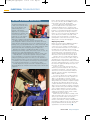
Ball gives the example of an ABS warning light on a truck
instrument panel. Having carried out the basic checks, he says, the
correct process starts with plugging in the diagnostic,
communicating with the ECU and looking for errors or fault codes.
“That will point to a circuit with a problem. It may be an ABS
sensor circuit fault, so you need to look at wheel speeds and
voltages by spinning the wheel. From there, you can determine is
there a problem, but then you need to revert back to normal testing
– checking the sensor resistance and looking for mechanical faults,
such as wheel bearing problems or corroded sensor rings.”
For Ball, diagnostics are part of the mix of troubleshooting. It’s
about blending good, old-fashioned technician practice with modern
equipment.
18
back to the ECU, unplug it and perform the same
test on the loom wires, with the DMM in resistance
mode. If that’s open circuit, it’s the wiring.
His point: although the fault might be with the
sensor, the diagnostic kit is only saying it can’t
communicate with the device. “Technicians who
don’t know any better tend to blindly fit what the kit
indicates as a potential problem. Often they will be
right – wheel speed sensors’ wiring, for instance,
tends to go across the suspension. By fitting a new
sensor, which comes with its own length of wire,
they may overcome the problem – even without
realising that it could, in fact, have been due to faulty
wiring or just a connector left unplugged.”
Scoping the problem
But it’s not just about using a DMM properly. Most
modern diagnostic equipment also includes
oscilloscope screens, capable of revealing vehicle
sensor and actuator waveforms. As Lock explains, if
the diagnostics are pointing to our wheel speed
sensor, but it’s not open circuit, then you can identify
exactly what’s going on by spinning the wheel in
question and then spinning another known good
wheel at the same speed, and comparing signals.
“If it turns out to be a weak signal, the problem
might not be the sensor itself. It could be a large air
gap between the sensor and rotor, or just debris
interfering with the magnetic field. Clearly, technicians
do need to understand the basics of sensors as well,
but at least the equipment will help them get to the
real cause,” he advises.
However, scopes really come into their own –
whether as part of the diagnostic kit or, even more,
as standalone instruments – when the problems
detected concern motorised actuators, which are
generally computer-controlled, using PWM (pulse
width modulation) signals.
“You can’t see what’s gong on with a voltmeter,
because the signals move too fast,” explains Lock.
“But a scope will draw you a picture of exactly
what’s happening. With the test leads clipped to the
wiring, it will show you what the computer is trying to
do, with its power switching signals. And you can
compare that with the actuator response around its
duty cycle. If it’s the throttle, for example, revving the
engine should show the pulse width signal changing,
as the computer attempts to move the actuator.
But, if the device stays put, then the fault is at the
actuator end. It might be seized or there could be
a fault with the actuator electrics.”
And it’s much the same with, for example, crank
shaft speed and position sensors. Here the value of
using a scope is that it enables a technician to
compare signal shape with that of the OEM’s
reference on the website – always ensuring that the
measurement conditions are the same. Clearly, with
properly administered electrical testing, there are
opportunities to save time and money. TE
October 2011 Transport Engineer