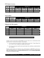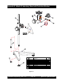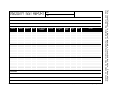
1
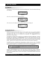
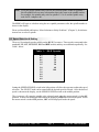
BROOKFIELD DIGITAL VISCOMETER MODEL DV-E Operating Instructions Manual No. M/98-350-D0902 SPECIALISTS IN THE MEASUREMENT AND CONTROL OF VISCOSITY BROOKFIELD ENGINEERING LABORATORIES, INC. 11 Commerce Boulevard, Middleboro, MA 02346-1031 USA TEL 800-628-8139 or 508-946-6200 F AX 508-946-6262 w w w. b ro o k f i e l d e n g i n e e r i n g . c o m Brookfield Engineering Labs., Inc. Page 1 Manual No. M/98-350-D0902 TABLE OF CONTENTS I. INTRODUCTION ................................................................................... 3 I.1 I.2 I.3 I.4 I.5 I.6 I.7 Components .................................................................................................................. 3 Utilities ......................................................................................................................... 4 Specifications ............................................................................................................... 4 Set-Up .......................................................................................................................... 4 Safety Symbols and Precautions .................................................................................. 5 Instrument Controls ...................................................................................................... 6 Cleaning ....................................................................................................................... 6 II. GETTING STARTED ............................................................................ 7 II.1 II.2 II.3 II.4 II.5 II.6 Power Up .................................................................................................................... 7 Spindle Selection ........................................................................................................ 7 Speed Selection & Setting .......................................................................................... 8 Autorange and CGS or SI Units Selection .................................................................. 9 Out of Range ............................................................................................................. 10 Operation................................................................................................................... 10 Appendix A - Viscosity Ranges .............................................................................................. 12 Appendix B - Variables in Viscosity Measurement ................................................................ 15 Appendix C - Spindle and Model Codes ................................................................................ 17 Appendix D - Calibration Procedures ..................................................................................... 19 Appendix E - Model A Laboratory Stand with Parts Identification ....................................... 25 Appendix F - Fault Diagnosis and Troubleshooting ............................................................... 27 Appendix G - Warranty Repair and Service ........................................................................... 29 Brookfield Engineering Labs., Inc. Page 2 Manual No. M/98-350-D0902 I. INTRODUCTION The Brookfield DV-E Viscometer measures fluid viscosity at given shear rates. Viscosity is a measure of a fluid’s resistance to flow. You will find a detailed description of the mathematics of viscosity in the Brookfield publication “More Solutions to Sticky Problems” a copy of which was included with your DV-E. The principle of operation of the DV-E is to rotate a spindle (which is immersed in the test fluid) through a calibrated spring. The viscous drag of the fluid against the spindle is measured by the spring deflection. Spring deflection is measured with a rotary transducer which provides a torque signal. The measurement range of a DV-E (in centipoise or milliPascal seconds) is determined by the rotational speed of the spindle, the size and shape of the spindle, the container in which the spindle is rotating, and the full scale torque of the calibrated spring. There are four basic spring torque series offered by Brookfield: Model LVDV-E RVDV-E HADV-E HBDV-E Spring Torque dyne-cm milli Newton-m 673.7 0.0673 7,187.0 0.7187 14,374.0 1.4374 57,496.0 5.7496 The higher the spring torque, the higher the measurement range. The viscosity measurement range for each spring torque may be found in Appendix A. All units of measurement are displayed according to either the CGS (cP) system or the SI (mPa•s) system. 1. Viscosity appears in units of centipoise (shown as “cP”) or milliPascal-seconds (shown as “mPa•s”) on the DV-E display. 2. Torque appears in units of dyne-centimeters or Newton-meters (shown as percent “%” in both cases) on the DV-E display. The equivalent units of measurement in the SI system are calculated using the following conversions: SI CGS Viscosity: 1 mPa•s = 1 cP Torque: 1 Newton-m = 107 dyne-cm References to viscosity throughout this manual are made in CGS units. The DV-E Viscometer provides equivalent information in SI units (see Section II.4 AUTORANGE). I.1 Components 1) 2) 3) 4) 5) 6) 7) DV-E Viscometer Laboratory Stand: Model A Spindle Set with Case (4 spindles for LVDV-E; 6 Spindles for RV, HA and HBDV-E). Power Cord Guard Leg (LVDV-E and RVDV-E only) Carrying Case Shipping Cap Please check to be sure that you have received all components, and that there is no damage. If you are missing any parts, please notify Brookfield Engineering or your local Brookfield agent immediately. Any shipping damage must be reported to the carrier. Brookfield Engineering Labs., Inc. Page 3 Manual No. M/98-350-D0902 I.2 Utilities Input Voltage: Input Frequency: Power Consumption: 115 VAC or 230 VAC 50/60 Hz Less than 20 WATTS Power Cord Color Code: Hot (live) Neutral Ground (earth) United States Black White Green Outside United States Brown Blue Green/Yellow I.3 Specifications Speeds: 0.3, 0.5, 0.6, 1.0, 1.5, 2.0, 2.5, 3.0, 4.0, 5.0, 6.0, 10, 12, 20, 30, 50, 60, 100 Weight: Gross Weight Net Weight Carton Volume Carton Dimension Operating Environment: Accuracy: 20 lb 17 lb 1.65 cu ft 19 x 10 x 15 in 9 kg 7.7 kg 0.05 m3 48 x 25 x 38 cm 0°C to 40°C Temperature Range (32°F to 104°F) 20% - 80% R.H.: non-condensing atmosphere ±1.0% Full Scale Range in Use (See Appendix D for details) Reproducibility: 0.2% of Full Scale Range Electrical Certifications: Conforms to CE Standards: BSEN 50081-1: BSEN 50082-1: BSEN 50081-2: BSEN 50082-2: BSEN 61010-1: Approved Standards: Emission Standard - Light Industrial Immunity Standard - Light Industrial Emission Standard - Industrial Immunity Standard - Industrial Safety requirements for electrical equipment, for measurement, control and laboratory use CSA Std. C22.2 No. 151-M1986 - Laboratory Equipment CSA Class 8721 81 - Laboratory Equipment This product has been certified to the applicable CSA and ANSI/UL Standards, for use in Canada and the U.S. Installation Category (over-voltage category) II: Classification of parts of installation systems or circuits in local level, portable equipment, appliances, etc.. I.4 Set-Up 1. To assemble the Model A Laboratory Stand, place the upright rod into the base (refer to assembly instructions in Appendix E). The rack gear and clamp assembly should face the front of the base. The upright rod is held in place with the jam nut which is attached from the bottom of the base. Tighten this nut with a suitable wrench (spanner). Attach leveling feet. Brookfield Engineering Labs., Inc. Page 4 Manual No. M/98-350-D0902 2. Insert the mounting rod on the back of the DV-E Viscometer into the hole on the clamp assembly. Be sure that the clamp screw, VS-41Y, is loose. 3. Adjust the Viscometer to be as close to level as possible while tightening the clamp screw. Tighten the VS-41Y clamp screw. 4. The Viscometer must be leveled. The level is adjusted using the three leveling screws on the base. Adjust so that the bubble level on top of the DV-E is centered within the circle. Note: Check level periodically during use. 5. Remove the Viscometer shipping cap from the pivot cup. This cap is designed to protect the Viscometer spindle coupling nut during shipment. Do not attempt to operate the Viscometer with the shipping cap in place! 6. Make sure that the AC power switch at the rear of the DV-E is in the OFF position. Connect the power cord to the socket on the back panel of the instrument and plug it into the appropriate AC line. The AC input voltage and frequency must be within the appropriate range as shown on the name plate of the viscometer. The DV-E must be earth grounded to ensure against electronic failure!! I.5 Safety Symbols and Precautions Safety Symbols The following explains safety symbols which may be found in this operating manual. Indicates hazardous voltages may be present. Refer to the manual for specific warning or caution information to avoid personal injury or damage to the instrument. Precautions If this instrument is used in a manner not specified by the manufacturer, the protection provided by the instrument may be impaired. This instrument is not intended for use in a potentially hazardous environment. In case of emergency, turn off the instrument and then disconnect the elecrical cord from the wall outlet The user should ensure that the substances placed under test do not release poisonous, toxic or flammable gases at the temperatures to which they are subjected to during the testing. Brookfield Engineering Labs., Inc. Page 5 Manual No. M/98-350-D0902 I.6 Instrument Controls The following describes each switch's function: MOTOR ON Turns the motor ON or OFF. AUTO RANGE Presents the maximum (100% torque) viscosity attainable using the selected spindle at the selected speed. This value is referred to as full scale range. The allowable error for the viscosity measurement is ± 1% of full scale range. Note: Pressing and holding the AUTO RANGE key during power on will enable the viscosity display to be read in either CGS (cP) or SI (mPa•s) units. SPEED/SPINDLE SWITCH Sets the viscometer in either speed select or spindle select (see Table C1 in Appendix C) mode. When set in the left position, the operator may select speed of rotation. When set in the right position, the operator may select spindle. Note: This is a three (3) position switch. We recommend that the switch be set to the middle position when finished with spindle or speed adjustment. This will prevent an accidental change of parameters during a test. SELECT KNOB This knob is used to scroll through the available speed or spindle selections (see Table C1 in Appendix C). This knob is active when the switch is set to the left (speed) or right (spindle) position. Rotate the knob clockwise to increase value and counter-clockwise to decrease value. I.7 Cleaning Be sure to remove spindle from instrument prior to cleaning. Severe instrument damage may result if cleaned in place. Instrument and Keypad: Clean with dry, non-abrasive cloth. Do not use solvents or cleaners. Immersed Components (spindles): Spindles are made of stainless steel. Clean with nonabrasive cloth and solvent appropriate for sample material that is not aggressive to immersed components. When cleaning, do not apply excessive force which may result in bending spindles. Brookfield Engineering Labs., Inc. Page 6 Manual No. M/98-350-D0902 II. GETTING STARTED II.1 Power Up Turn the power switch (located on the rear panel) to the ON position. This will result in the following screen display: BROOKFIELD DV-E RV VISCOMETER Figure II-1 After a few seconds, the following screen appears: BROOKFIELD VERSION: DV-E 1.00 Figure II-2 After a short time, the display will clear and the default screen is displayed: cP 1ØOFF % S01 Figure II-3 II.2 Spindle Selection LVDV-E Viscometers are provided with a set of four spindles and a narrow guardleg; RVDV-E Viscometers come with a set of six spindles and a “wider” guardleg; HADV-E and HBDV-E Viscometers come with a set of six spindles and no guardleg. (See Appendix D for more information on the guardleg.) The spindles are attached to the viscometer by screwing them to the male coupling nut. Note that the spindles and coupling have a left-hand thread. The lower shaft should be held in one hand (lifted slightly), and the spindle screwed to the left. The face of the spindle nut and the matching surface on the coupling nut shaft should be smooth and clean to prevent eccentric rotation of the spindle. Spindles can be identified by the number on the side of the spindle coupling nut. The DV-E must have a Spindle Entry Code number to calculate viscosity values. The DV-E memory contains parameters for all standard Brookfield spindles and the two digit entry code for each spindle (the complete list of spindle entry codes may be found in Appendix C). Note: The DV-E will display the Spindle Entry Code which was in use when power was turned off. Setting the SPEED/SPINDLE switch to the right position will allow the operator to adjust the spindle selection. The SELECT knob can be rotated until the desired spindle number is selected. Once the desired spindle number is shown on the display, set the SPINDLE/SPEED switch to the middle position. Brookfield Engineering Labs., Inc. Page 7 Manual No. M/98-350-D0902 Note: Verify the proper spindle entry code for the selected spindle found in Appendix C. Not all spindles have an entry code number that is the same as the spindle number. For example: the spindle entry code for spindle LV1 is 61 and the spindle entry code for UL Adapter is 00. The DV-E will begin to calculate using the new spindle parameters after the spindle number is shown in the display. Please see Brookfield publication, “More Solutions to Sticky Problems” (Chapter 3), for information on how to select a spindle. II.3 Speed Selection & Setting There are 18 rotational speeds available on the DV-E Viscometer. These speeds correspond to the standard LVF, LVT, RVF, RVT, HAT and HBT models, and they are combined sequentially. See Table 1 below. Table 1: 0.3 0.5 0.6 1.0 1.5 2.0 2.5 3.0 4.0 5.0 6.0 DV-E Speeds 10 12 20 30 50 60 100 Setting the SPEED/SPINDLE switch in the left position will allow the operator to adjust the speed selection. The SELECT knob can be rotated until the desired speed is selected. Once the desired speed is shown on the display, set the SPINDLE/SPEED switch to the middle position. The viscometer will rotate the spindle at the selected speed when the motor switch is in the ON position. A motor on condition is indicated on the display by RPM shown beside the speed. When the motor switch is in the OFF position, OFF will be displayed beside the speed. Brookfield Engineering Labs., Inc. Page 8 Manual No. M/98-350-D0902 cP 12RPM % S01 (MOTOR ON) cP 12OFF % S01 (MOTOR OFF) Figure II-4 Note: When the motor switch is in the ON position, any change to the selected speed will be effective immediately. When collecting data at multiple speeds, you may wish to leave the SPEED/SPINDLE switch in the left position to facilitate speed changes. To make a viscosity measurement, follow the instructions in Sections II.2 and II.3. Allow time for the indicated reading to stabilize. Note: At speeds of 1 RPM and lower, additional time may be required to allow for complete deflection of the torque sensor. The time required for stabilization will depend on the speed at which the Viscometer is running and the characteristics of the sample fluid. For maximum accuracy, readings below 10% should be avoided. Additional information on making viscosity measurements is available in Appendix B or the Brookfield publication “More Solutions to Sticky Problems” . The DV-E Viscometer will remember the selected speed and spindle when power is turned off. On start-up, the Viscometer will be set to the previously selected spindle and speed. Please see Brookfield publication “ More Solutions to Sticky Problems” (Chapter 3) for information on how to select a speed. II.4 Autorange and CGS or SI Units Selection The AUTO RANGE key allows you to determine the maximum calculated viscosity (full scale reading) possible with the current spindle/speed setting. Pressing the key at any time will cause the current viscosity display to change and show that maximum viscosity. The screen torque display will now display “%100” to indicate this special condition. This maximum viscosity and %100 value will be displayed for as long as the AUTO RANGE key is depressed. Figure II-5 shows the AUTO RANGE function for the situation where the No. 1 RV spindle is rotating at 10 RPM. The full scale range is 1000 cP (or 1000 mPa.s). cP 1000 10RPM %100 S01 Figure II-5 Brookfield Engineering Labs., Inc. Page 9 Manual No. M/98-350-D0902 Pressing and holding the AUTO RANGE key during power on will enable the viscosity unit displayed to toggle between CGS (cP) and SI (mPa•s) units. To change the unit format: 1. Turn the power off. 2. Press and hold the AUTO RANGE key and turn the power ON. The DV-E will retain the unit selection when the viscometer is turned OFF. CGS Viscosity: SI cP mPa.s 1 cP = 1 mPa•s II.5 Out of Range The DV-E gives indications for out of specification or out-of-range operation. When % (Torque) readings exceed 100.0 % (over-range), the display changes to that shown in Figure II-6: cP EEEE 10RPM %EEEE S01 Figure II-6 You must change either speed or spindle to correct this condition. If you operate at spindle speeds that produce % (Torque) below 10.0 % (under-range), the DV-E displays both % (Torque) and cP (Viscosity) with flashing unit designations. The parameters of % (Torque) and cP (Viscosity) will also flash prior to one complete spindle revolution. It is not recommended that readings are taken while parameters are flashing. cP 9.0 10RPM % 9.0 S01 Figure II-7 Negative % (Torque) will be displayed as shown in Figure 8: cP ---10RPM %-1.0 S01 Figure II-8 Viscosity values will be displayed as “- - - -” when the % (Torque) is below zero. II.6 Operation The following procedure is outlined for making a viscosity measurement in a 600 mL low form Griffin beaker. 1. Mount the guardleg on the DV-E Viscometer (LV and RV series). Be sure that the motor is OFF before attaching the spindle. Select a spindle and attach it to the lower shaft. Lift the shaft slightly, holding it firmly with one hand while screwing the spindle on with the other (note lefthand thread). Avoid putting side thrust on the shaft. Brookfield Engineering Labs., Inc. Page 10 Manual No. M/98-350-D0902 2. Insert and center spindle in the test material until the fluid's level is at the immersion groove on the spindle's shaft. With a disc-type spindle, it is sometimes necessary to tilt the spindle slightly while immersing to avoid trapping air bubbles on its surface. (You may find it more convenient to immerse the spindle in this fashion before attaching it to the Viscometer.) 3. To make a viscosity measurement, select a speed and follow the instructions in Sections II.2 and II.3. Allow time for the indicated reading to stabilize. The time required for stabilization will depend on the speed at which the Viscometer is running and the characteristics of the sample fluid. For maximum accuracy, readings below 10% should be avoided. Additional information on making viscosity measurements is available in Appendix B or the Brookfield publication “More Solutions to Sticky Problems”. 4. Switch the MOTOR ON/OFF switch to turn the motor “OFF” when changing a spindle or changing samples. Remove spindle before cleaning. 5. Interpretation of results and the instrument's use with non-Newtonian and thixotropic materials is discussed in the booklet, “More Solutions to Sticky Problems”, and in Appendix B, Variables in Viscosity Measurements. Brookfield Engineering Labs., Inc. Page 11 Manual No. M/98-350-D0902 Appendix A - Viscosity Ranges LV and RV,HA,HB Viscometers Viscosity Range (cP) Viscometer Minimum Maximum LVDV-E RVDV-E HADV-E HBDV-E 15 100 200 800 2M 13 M 26 M 106 M Small Sample Adapter and Thermosel Viscosity (cP) SSA/Thermosel Spindle Shear Rate (1/SEC) SC4-16 (SSA) SC4-18 (SSA/Tsel) SC4-25 (SSA) SC4-31 (SSA/Tsel) SC4-34 (SSA/Tsel) HT-81 (Tsel) SC4-82 (SSA) SC4-83 (SSA) 0.29 N 1.32 N 0.22 N 0.34 N 0.28 N 1.29 N 1.29 N 1.29 N LVDV-E 120 3 800 30 60 3.5 3.5 11.0 - 400 K 10 K 1.60 M 100 K 200 K 10 K 10 K 38 K Viscosity (cP) (cP) Viscosity SSA/ Thermosel Spindle Shear Rate (1/SEC) SC4-14 (SSA) SC4-15 (SSA) SC4-21 (SSA/Tsel) SC4-27 (SSA/Tsel) SC4-28 (SSA/Tsel) SC4-29 (SSA/Tsel) HT-81 (Tsel) SC4-82 (SSA) SC4-83 (SSA) 0.40N 0.48N 0.93N 0.34N 0.28N 0.25N 1.29N 1.29N 1.29N RVDV-E 1.25K 500 50 250 500 1K 36 36 121 - HADV-E 4.2 M 1.7 M 170 K 830 K 1.7 M 3.3 M 10 K 10 K 50 K 2.5 M 1M 100 500 1M 2M 73 73 242 - HBDV-E 8.3 M 3.3 M 300 K 1.7 M 3.3 M 6.7 M 10 K 10 K 50 K 10 M 4M 400 2M 4M 8M 292 292 970 - 33.3 M 13.3 M 1.3 M 6.7 M 13.3 M 26.7 M 10 K 10 K 50 K UL Adapter Viscosity Viscosity (cP) (cP) UL Spindle YULA-15 or 15Z Shear Rate (1/SEC) LVDV-E RVDV-E HADV-E HBDV-E 1.224N 1.0 - 2 K 6.4 - 2 K 12.8 - 2 K 51.2 - 2 K K = 1,000 Brookfield Engineering Labs., Inc. M = 1,000,000 Page 12 N = RPM Manual No. M/98-350-D0902 DIN Adapter Accessory Viscosity Viscosity (cP)(cP) DAA Spindle Shear Rate (1/SEC) LVDV-E 85 86 87 1.29N 1.29N 1.29N 1.2 - 3.8 K 3 - 10 K 11 - 38 K RVDV-E HADV-E 12 - 5 K 36 - 10 K 12 - 50 K 24 73 242 - HBDV-E 5K 10 K 50 K 98 - 5 K 292 - 10 K 970 - 50 K Spiral Adapter DAA Spindle SA-70 Viscosity (cP) Viscosity (cP) Shear Rate (1/SEC) LVDV-E RVDV-E HADV-E HBDV-E 0.68 - 68 100 - 98 K 1M-1M 2M-2M 8 M - 8.4 M (1-100 RPM) Helipath with T-Bar Spindles Viscosity (cP)Viscosity (cP) T-Bar Spindle T-A T-B T-C T-D T-E T-F LVDV-E 156 312 780 1.5 M 3.9 M 7.8 M - 62 K 124 K 312 K 624 K 1.5 M 3.1 M RVDV-E 2M 4M 10 M 20 M 50 M 100 M K = 1,000 - HADV-E 400 K 800 K 2M 4M 10 M 20 M 4M 8M 20 M 40 M 100 M 200 M M = 1,000,000 - HBDV-E 800 K 1.6 M 4M 8M 20 M 40 M 16 M 32 M 80 M 160 M 400 M 800 M - 3.2 M 6.4 M 16 M 32 M 80 M 160 M N = RPM In taking viscosity measurements with the DV-E Viscometer, there are two considerations which pertain to the low viscosity limit of effective measurement. 1) Viscosity measurements should be accepted within the equivalent % Torque Range from 10% to 100% for any combination of spindle/speed rotation. 2) Viscosity measurements should be taken under laminar flow conditions, not under turbulent flow conditions. The first consideration has to do with the accuracy of the instrument. All DV-E Viscometers have a full scale range accuracy of (+/-) 1% of any spindle/speed rotation. We discourage taking readings below 10% of range because the potential viscosity error of (+/-) 1% is a relatively high number compared to the instrument reading. Brookfield Engineering Labs., Inc. Page 13 Manual No. M/98-350-D0902 The second consideration involves the mechanics of fluid flow. All rheological measurements of fluid flow properties should be made under laminar flow conditions. Laminar flow is flow wherein all particle movement is in layers directed by the shearing force. For rotational systems, this means all fluid movement must be circumferential. When the inertial forces on the fluid become too great, the fluid can break into turbulent flow wherein the movement of fluid particles becomes random and the flow can not be analyzed with standard math models. This turbulence creates a falsely high viscometer reading with the degree of non-linear increase in reading being directly related to the degree of turbulence in the fluid. For the following geometries, we have found that an approximate transition point to turbulent flow occurs: 1) 2) 3) No. 1 LV (optional) Spindle: No. 1 RV (optional) Spindle: UL Adapter: 15 cP at 60 RPM 100 cP at 50 RPM 0.85 cP at 60 RPM Turbulent conditions will exist in these situations whenever the RPM/cP ratio exceeds the values listed above. Brookfield Engineering Labs., Inc. Page 14 Manual No. M/98-350-D0902 Appendix B - Variables in Viscosity Measurement As with any instrument measurement, there are variables that can affect a viscometer measurement. These variables may be related to the instrument (viscometer), or the test fluid. Variables related to the test fluid deal with the rheological properties of the fluid, while instrument variables would include the viscometer design and the spindle geometry system utilized. Rheological Properties Fluids have different rheological characteristics that can be described by viscometer measurements. We can then work with these fluids to suit the lab or process conditions. There are two categories of fluids: Newtonian - These fluids have the same viscosity at different Shear Rates (different RPM’s) and are called Newtonian over the Shear Rate range they are measured. Non-Newtonian - These fluids have different viscosities at different shear rates (different RPM’s). They fall into two groups: 1) Time Independent 2) Time Dependent Time Independent means that the viscosity behavior does not change as a function of time when measuring at a specific shear rate. Pseudoplastic - A pseudoplastic material displays a decrease in viscosity with an increase in shear rate, and is also known as “shear thinning”. If you take viscometer readings from a low to a high RPM and then back to the low RPM, and the readings fall upon themselves, the material is time independent ,pseudoplastic and shear thinning. Time Dependent means that the viscosity behavior changes as a function of time when measuring at a specific shear rate. Thixotropic - A thixotropic material has decreasing viscosity under constant shear rate. If you set a viscometer at a constant speed recording viscosity values over time and find that the viscosity values decrease with time, the material is thixotropic. Brookfield publication, “More Solutions to Sticky Problems”, includes a more detailed discussion of rheological properties and non-Newtonian behavior. Viscometer Related Variables Most fluid viscosities are found to be non-Newtonian. They are dependent on Shear Rate and the spindle geometry conditions. The specifications of the viscometer spindle and chamber geometry will affect the viscosity readings. If one reading is taken at 2.5 rpm, and a second at 50 rpm, the two viscosity values produced will be different because the readings were made at different shear rates. The faster the spindle speed, the higher the shear rate. Brookfield Engineering Labs., Inc. Page 15 Manual No. M/98-350-D0902 The shear rate of a given measurement is determined by: the rotational speed of the spindle, the size and shape of the spindle, the size and shape of the container used and therefore, the distance between the container wall and the spindle surface. A repeatable viscosity test should control or specify the following: 1) 2) 3) 4) 5) 6) 7) Test temperature Sample container size (or spindle/chamber geometry) Sample volume Viscometer model Spindle used (if using LVDV-E (#1-4) or RVDV-E (#2-7) attach the guard leg) Test speed or speeds (or the shear rate) Length of time or number of spindle revolutions to record viscosity. Brookfield Engineering Labs., Inc. Page 16 Manual No. M/98-350-D0902 Appendix C - Spindle and Model Codes Each spindle has a two digit code which is scrolled via the select knob on the DV-E. The spindle code directs the DV-E to calculate viscosity for the spindle that is being used. The spindle multiplyer constant (SMC) is used to calculate full scale viscosity range for any spindle/speed combination (refer to Appendix D). Spindle codes are listed in Table C-1. Table C-1 SPINDLE RV1 (optional) RV2 RV3 RV4 RV5 RV6 RV7 HA1 (optional) HA2 HA3 HA4 HA5 HA6 HA7 HB1 (optional) HB2 HB3 HB4 HB5 HB6 HB7 LV1 LV2 LV3 LV4 LV5 SPIRAL CODE 01 02 03 04 05 06 07 01 02 03 04 05 06 07 01 02 SMC 1 4 10 20 40 100 400 1 4 10 20 40 100 400 1 4 03 04 05 06 07 61 62 63 64 65 70 10 20 40 100 400 6.4 32 128 640 1280 105 Brookfield Engineering Labs., Inc. SPINDLE T-A T-B T-C T-D T-E T-F ULA DIN-ULA TSEL-DIN-81 SSA-DIN-82 SSA-DIN-83 ULA-DIN-85 ULA-DIN-86 ULA-DIN-87 SC4-14 SC4-15 SC4-16 SC4-18 SC4-21 SC4-25 SC4-27 SC4-28 SC4-29 SC4-31 SC4-34 SC4-37 Page 17 CODE 91 92 93 94 95 96 00 85 81 82 83 85 86 87 14 15 16 18 21 25 27 28 29 31 34 37 SMC 20 40 100 200 500 1000 0.64 1.22 3.7 3.75 12.09 1.22 3.65 12.13 125 50 128 3.2 5 512 25 50 100 32 64 25 Manual No. M/98-350-D0902 Table C-2 lists the model codes and spring torque constants for each viscometer model. Table C-2 VISCOMETER MODEL TORQUE CONSTANT TK MODEL CODE ON DV-E SCREEN LVDV-E 0.09373 LV RVDV-E 1 RV HADV-E 2 HA HBDV-E 8 HB SPECIAL ORDER TORQUE SPRINGS VISCOMETER MODEL TORQUE CONSTANT TK MODEL CODE ON DV-E SCREEN 2.5xLVDV-E 0.2343 2.5LV 5xLVDV-E 0.4686 5LV 1/4 RVDV-E 0.25 1/4RV 1/2 RVDV-E 0.5 1/2RV 2xHADV-E 4 2HA 2.5xHADV-E 5 2.5HA 2xHBDV-E 16 2HB 2.5xHBDV-E 20 2.5HB 5xHBDV-E 40 5HB Brookfield Engineering Labs., Inc. Page 18 Manual No. M/98-350-D0902 Appendix D - Calibration Procedures The accuracy of the DV-E is verified using viscosity standard fluids which are available from Brookfield Engineering Laboratories or your local Brookfield agent. Viscosity standards are Newtonian, and therefore, have the same viscosity regardless of spindle speed (or shear rate). Viscosity standards, calibrated at 25°C, are shown in Table D-1. Container size: For Viscosity Standards < 30,000 cP, use a 600 ml Low Form Griffin Beaker having a working volume of 500 ml. For Viscosity Standards ≥ 30,000 cP, use the fluid container. Inside Diameter: 3.25"(8.25cm) Height: 4.75"(12.1cm) Note: Container may be larger, but may not be smaller. Temperature: Conditions: As stated on the fluid standard label: (+/-) 0.1°C The DV-E should be set according to the operating instructions. The water bath should be stabilized at test temperature. Viscometers with the letters “LV” or “RV” in the model designation should have the guard leg attached. Normal 25°C Standard Fluids Viscosity (cP) Viscosity (cP) 5 10 50 100 500 1,000 5,000 12,500 30,000 60,000 100,000 High Temperature Standard Fluids for use with Thermosel Accessory HT-30,000 HT-60,000 HT-1000,000 Calibrated at three viscosity/temperatures 25°C, 93.3°C, 149°C Refer to Brookfield catalog for more information. Table D-1(Silicone Oils) Brookfield Viscosity Standard Fluid - General Information We recommend that Brookfield Viscosity Standard Fluids be replaced on an annual basis, one year from date of initial use. These fluids are pure silicone and are not subject to change over time. However, exposure to outside contaminants through normal use requires replacement on an annual basis. Contamination may occur by the introduction of solvent, standard of different viscosity or other foreign material. Viscosity Standard Fluids may be stored under normal laboratory conditions. Disposal should be in accordance with state, local and federal regulations as specified on the material safety data sheet. Brookfield Engineering Laboratories does not recertify Viscosity Standard Fluids. We will issue duplicate copies of the Certificate of Calibration for any fluid within two years of the purchase date. Brookfield Viscosity Standard Fluids are reusable provided they are not contaminated. Normal Brookfield Engineering Labs., Inc. Page 19 Manual No. M/98-350-D0902 practice for usage in a 600 ml beaker is to return the material from the beaker back into the bottle. When using smaller volumes in accessories such as Small Sample Adapter, UL Adapter, Thermosel or Spiral Adapter, the fluid is normally discarded. Calibration Procedure for LV(#1-4) and RV,HA,HB(#2-7) Brookfield spindles: 1) Place the viscosity standard fluid (in the proper container) into the water bath. 2) Lower the DV-E into measurement position (with guard leg if LV or RV series viscometer is used). 3) Attach the spindle to the viscometer. If you are using a disk shaped spindle, avoid trapping air bubbles beneath the disk by first immersing the spindle at an angle, and then connecting it to the viscometer. 4) The viscosity standard fluid, together with the spindle and guard leg (if supplied), should be immersed in the bath for a minimum of 1 hour, stirring the fluid periodically, prior to taking measurements. 5) After 1 hour, check the temperature of the viscosity standard fluid with an accurate thermometer. Fluid must be within ± 0.1°C of the specified temperature, normally 25°C. Allow longer soak time if required to come to test temperature. 6) If the fluid is at test temperature, measure the viscosity and record the viscometer reading. Note: The spindle must rotate at least five (5) times before readings are taken. 7) The viscosity reading should equal the cP value on the viscosity fluid standard to within the combined accuracies of the viscometer and the standard (as discussed in the section entitled, Interpretation of Calibration Test Results). Calibration Procedure for a Small Sample Adapter When a Small Sample Adapter is used, the water jacket is connected to the water bath and the water is stabilized at the proper temperature: 1) Put the proper amount of viscosity standard fluid into the sample chamber. The amount varies with each spindle/chamber combination. (Refer to the Small Sample Adapter instruction manual.) 2) Place the sample chamber into the water jacket. 3) Put the spindle into the test fluid and attach the extension link, coupling nut and free hanging spindle (or directly attach the solid shaft spindle) to the DV-E. 4) Allow 30 minutes for the viscosity standard, sample chamber and spindle to reach test temperature. 5) Measure the viscosity and record the viscometer reading. Note: The spindle must rotate at least five (5) times before a viscosity reading is taken. Calibration Procedure for a Thermosel System A two-step process is recommended for the Thermosel. Brookfield Engineering Labs., Inc. Page 20 Manual No. M/98-350-D0902 A) Evaluate the calibration of the Viscometer alone according to the procedure outlined in this section, entitled Calibration Procedure for LV (#1-4) and RV,HA,HB (#2-7) Brookfield spindles. B) Evaluate the Viscometer with the Thermosel according to the procedure decribed below. When a Thermosel is used, the controller stabilizes the Thermo Container at the test temperature. 1) Install the tube end cap and put the proper amount of HT viscosity standard fluid into the HT-2 or HT-2DB sample chamber. The amount varies with the spindle used. (Refer to the Thermosel instruction manual). 2) Place the sample chamber into the Thermo Container. 3) Put the spindle into the test fluid and attach the extension link, coupling nut and free hanging spindle (or directly attach the solid shaft spindle) to the DV-E. 4) Allow 30 minutes for the viscosity standard, sample chamber and spindle to reach test temperature. 5) Measure the viscosity and record the viscometer reading. Note: The spindle must rotate at least five (5) times before a viscosity reading is taken. Calibration Procedure for UL Adapter When a UL Adapter is used, the water bath should be stabilized at the proper temperature: 1) Install the tube end cap and put the proper amount of viscosity standard fluid into the UL Tube. (Refer to the UL Adapter instruction manual). 2) Attach the spindle (with extension link and coupling nut) onto the DV-E. 3) Attach the tube to the mounting channel. 4) Lower the tube into the water bath reservoir, or if using the ULA-40Y water jacket, connect the inlet/outlets to the bath external circulating pump. 5) Allow 30 minutes for the viscosity standard, sample chamber and spindle to reach test temperature. 6) Measure the viscosity and record the viscometer reading. Note: The spindle must rotate at least five (5) times before a viscosity reading is taken. Calibration Procedure for DIN Adapter Accessory When a DIN Adapter is used, the water bath should be stabilized at the proper temperature: 1) Put the proper amount of viscosity standard fluid into the UL Tube. (Refer to the DAA instruction manual). 2) Attach the spindle (with extension link and coupling nut) onto the DV-E. Brookfield Engineering Labs., Inc. Page 21 Manual No. M/98-350-D0902 3) Attach the tube to the mounting channel. 4) Lower the tube into the water bath reservoir, or if using the ULA-40Y water jacket, connect the inlet/outlets to the bath external circulating pump. 5) Allow 30 minutes for the viscosity standard, sample chamber and spindle to reach test temperature. 6) Measure the viscosity and record the viscometer reading. Note: The spindle must rotate at least five (5) times before a viscosity reading is taken. Calibration Procedure for a Helipath Stand and T-Bar Spindles When a Helipath Stand and T-Bar spindles are used: it is not recommended to use T-bar spindles to check calibration. Remove the T-bar spindle and select a standard LV(#1-4) or RV,HA,HB(#2-7) spindle. Follow the procedures for using LV and RV,HA,HB Brookfield spindles outlined on page 18. T-Bar spindles should not be used for verifying calibration of the DV-E Viscometer. Calibration Procedure for Spiral Adapter 1) Place the viscosity standard fluid (in the proper container) into the water bath. 2) Attach the spindle to the viscometer. Attach chamber (SA-1Y) and clamp to the viscometer. 3) Lower the DV-E into measurement position. Operate the viscometer at 50 or 60 RPM until the chamber is fully flooded. 4) The viscosity standard fluid, together with the spindle, should be immersed in the bath for a minimum of 1 hour, stirring the fluid periodically (operate at 50 or 60 RPM periodically), prior to taking measurements. 5) After 1 hour, check the temperature of the viscosity standard fluid with an accurate thermometer. 6) If the fluid is at test temperature (+/- 0.1°C of the specified temperature, normally 25°C), measure the viscosity and record the viscometer reading. Note: The spindle must rotate at least five (5) times for one minute, whichever is greater before readings are taken. 7) The viscosity reading should equal the cP value on the viscosity fluid standard to within the combined accuracies of the viscometer and the standard (as discussed in the section entitled, Interpretation of Calibration Test Results). Interpretation of Calibration Test Results: When verifying the calibration of the DV-E, the instrument and viscosity standard fluid error must be combined to calculate the total allowable error. The DV-E is accurate to (+/-) 1% of any full scale spindle/speed viscosity range. Brookfield Viscosity Standards Fluids are accurate to (+/-) 1% of their stated value. Brookfield Engineering Labs., Inc. Page 22 Manual No. M/98-350-D0902 EXAMPLE: Calculate the acceptable range of viscosity using RVDV-E with RV-3 Spindle at 2 RPM; Brookfield Standard Fluid 12,500 with a viscosity of 12,257 cP at 25°C: 1) Calculate full scale viscosity range using the equation: Full Scale Viscosity Range [cP] = TK * SMC * 10,000 RPM Where: TK = 1.0 from Table C2 SMC = 10 from Table C1 Full Scale Viscosity Range = 1 * 10 * 10,000 = 50,000 cP 2 The viscosity is accurate to (+/-) 500 cP (which is 1% of 50,000) 2) The viscosity standard fluid is 12,257 cP. Its accuracy is (+/-)1% of 12,257 or (+/-)122.57 cP. 3) Total allowable error is (122.57 + 500) cP = (+/-) 622.57 cP. 4) Therefore, any viscosity reading between 11,634.4 and 12,879.6 cP indicates that the viscometer is operating correctly. Any reading outside these limits may indicate a viscometer problem. Contact the Brookfield technical sales department or your local Brookfield dealer/distributor with test results to determine the nature of the problem. The Brookfield Guardleg The guard leg was originally designed to protect the spindle during use. The first applications of the Brookfield Viscometer included hand held operation while measuring fluids in a 55 gallon drum. It is clear that under those conditions the potential for damage to the spindle was great. The current guard leg is a band of metal in the shape of the letter U with a bracket at the top that attaches to the pivot cup of a Brookfield Viscometer/Rheometer. A guard leg is supplied with all LV and RV series instruments, but not with the HA or HB series. It’s shape is designed to accommodate the spindles of the appropriate spindle set; therefore, the RV guard leg is wider than the LV due to the large diameter of the RV #1 (optional) spindle. They are not interchangeable. The calibration of the Brookfield Viscometer/Rheometer is determined using a 600 ml Low Form Griffin Beaker. The calibration of LV and RV series instruments includes the guard leg. The beaker wall (for HA/HB instruments) or the guard leg (for LV/RV instruments) define what is called the “outer boundary” of the measurement. The spindle factors for the LV, RV, and HA/HB spindles were developed with the above boundary conditions. The spindle factors are used to convert the instrument torque (expressed as the dial reading or %Torque value) into centipoise. Theoretically, if measurements are made with different boundary conditions, e.g., without the guard leg or in a container other than 600 ml beaker, then the spindle factors found on the Factor Finder cannot be used to accurately calculate an absolute viscosity. Changing the boundary conditions does not change the viscosity of the fluid, but it does change how the instrument torque is converted to centipoise. Without changing the spindle factor to suit the new boundary conditions, the calculation from instrument torque to viscosity will be incorrect. Practically speaking, the guard leg has the greatest effect when used with the #1 & #2 spindles of the LV and RV spindle sets. Any other LV (#3 & #4) or RV (#3 - #7) spindle can be used in a 600 ml beaker with or without the guard leg to produce correct results. The HA and HB series Viscometers/ Brookfield Engineering Labs., Inc. Page 23 Manual No. M/98-350-D0902 Rheometers are not supplied with guard legs in order to reduce the potential problems when measuring high viscosity materials. HA/HB spindles #3 through #7 are identical to those spindle numbers in the RV spindle set. The HA/HB #1 & #2 have slightly different dimensions than the corresponding RV spindles. This dimensional difference allows the factors between the RV and HA/HB #1 spindles to follow the same ratios as the instrument torque even though the boundary conditions are different. The recommended procedures of using a 600 ml beaker and the guard leg are difficult for some customers to follow. The guard leg is one more item to clean. In some applications the 500 ml of test fluid required to immerse the spindles in a 600 ml beaker is LV Guardleg RV Guardleg not available. In practice, a smaller vessel may be used and the guard leg is removed. The Brookfield Viscometer/Rheometer will produce an accurate and repeatable torque reading under any measurement circumstance. However, the conversion of this torque reading to centipoise will only be correct if the factor used was developed for those specific conditions. Brookfield has outlined a method for recalibrating a Brookfield Viscometer/Rheometer to any measurement circumstance in “More Solutions to Sticky Problems”, Section 3.3.10. It is important to note that for many viscometer users the true viscosity is not as important as a repeatable day to day value. This repeatable value can be obtained without any special effort for any measurement circumstance. But, it should be known that this type of torque reading will not convert into a correct centipoise value when using a Brookfield factor if the boundary conditions are not those specified by Brookfield. The guard leg is a part of the calibration check of the Brookfield LV and RV series Viscometer/ Rheometer. Our customers should be aware of its existence, its purpose and the effect that it may have on data. With this knowledge, the viscometer user may make modifications to the recommended method of operation to suit their needs. Brookfield Engineering Labs., Inc. Page 24 Manual No. M/98-350-D0902 Appendix E - Model A Laboratory Stand with Parts Identification 1 2 3 4 5 6 7 8 9 10 11 12 VS-20 VS-1 VS-3 VS-21 VS-35 VS-40Y VS-41Y VS-29 VS-29W VS-28 50S103208S25B BLM-4E BLM-4E2 UPRIGHT ROD BASE LEVELING SCREW JAM NUT CLAMP GEAR SCREW ASSEMBLY CLAMP SCREW ASSEMBLY TENSION INSERT BELLEVILLE SPRING WASHER TENSION SCREW SCREW, 4-40 X 3/8 LG. SOC. HD. CAP, 18-8 SS ROD EXTENSION-4" LONG RODE EXTENSION - 8" LONG 1 1 3 1 1 1 1 1 2 1 1 OPTIONAL OPTIONAL Figure E-1 Brookfield Engineering Labs., Inc. Page 25 Manual No. M/98-350-D0902 Unpacking Check carefully to see that all the components are received with no concealed damage. 1 base 3 leveling screws 1 upright rod 1 jam nut 1 clamp assembly Remove the three (3) leveling screws from the base and discard the packing material. Remove the jam nut from the upright rod. Assembly (Refer to Figure E1) Screw the leveling screws into the base. Insert the threaded end of the upright rod into the hole in the top of the base and attach the jam nut to the rod on the underside of the base. With the rod gear rack facing forward (toward the “V” in the base), gently tighten the jam nut. Viscometer Mounting The VS-35Y clamp assembly should be positioned so that the word ‘front’ is facing the operator. This will ensure the cut-away slot of the clamp assembly will align properly with the machined key ridge of the viscometer handle. Insert the viscometer rod into the cut-away hole of the clamp assembly. Adjust the instrument level until the bubble is centered within the target and tighten the clamp screw, VS-26Y. The small clamp adjusting screw (Figure E1) on the front of the clamp assembly should be loosened or tightened as necessary to provide smooth height adjustment and adequate support for the Viscometer. Center the Viscometer relative to the stand base and retighten the jam nut as required. Referring to the Viscometer bubble level, adjust the leveling screws until the instrument is level. Operation Rotate the Gear Screw to raise or lower the viscometer. Brookfield Engineering Labs., Inc. Page 26 Manual No. M/98-350-D0902 Appendix F - Fault Diagnosis and Troubleshooting Listed are some of the more common problems that you may encounter while using your DV-E Viscometer. Review these items before you contact Brookfield. Spindle Does Not Rotate ❏ Make sure the viscometer is plugged in. ❏ Check the voltage rating on your viscometer (115V, 220V): it must match the wall voltage. ❏ Make sure the power switch is in the ON position. ❏ Make sure the speed set knob is set properly and securely at the desired speed. Spindle Wobbles When Rotating or Looks Bent ❏ Make sure the spindle is tightened securely to the viscometer coupling. ❏ Check the straightness of all other spindles; replace them if bent. ❏ Inspect viscometer coupling and spindle coupling mating areas and threads for dirt: clean threads on spindle coupling with a 3/56 left-hand tap. ❏ Inspect threads for wear; if the threads are worn, the unit needs service (see Appendix G). ❏ Check to see if spindles rotate eccentrically or wobble. There is an allowable runout for 1/ 32-inch in each direction (1/16-inch total) when measured from the bottom of the spindle rotating in air. ❏ Check to see if the viscometer coupling is bent; if so, the unit is in need of service. If the pointer sticks and/or does not rest at zero, the unit is need of service. See Appendix G for details on how to return your viscometer. Inaccurate Readings ❏ Verify spindle, speed and model selection ❏ Verify test parameters: temperature, container, volume, method. Refer to: • "More Solutions to Sticky Problems"; Section II.2a — Considerations for Making Measurements • Dial Viscometer Operating Manual; Appendix B — Viscosity Ranges • Dial Viscometer Operating Manual; Appendix C — Variables in Viscosity Measurement Brookfield Engineering Labs., Inc. Page 27 Manual No. M/98-350-D0902 ❏ Perform a calibration check. Follow the instructions in Appendix D. • Verify tolerances are calculated correctly. • Verify calibration check procedures were followed exactly If the unit is found to be out of tolerance, the unit may be in need of service. See Appendix H for details on how to return your viscometer. Brookfield Engineering Labs., Inc. Page 28 Manual No. M/98-350-D0902 Appendix G - Warranty Repair and Service Warranty Brookfield Viscometers are guaranteed for one year from date of purchase against defects in materials and workmanship. The Viscometer must be returned to Brookfield Engineering Laboratories, Inc. or the Brookfield dealer from whom it was purchased for no charge warranty evaluation service. Transportation is at the purchaser’s expense. The Viscometer should be shipped in its carrying case together with all spindles originally provided with the instrument as shown below. ❏ Remove and return all spindles (properly packed for shipping). ❏ Clean excess testing material off the instrument. ❏ Include MSDS sheets for all materials tested with this instrument. ❏ Protect the pointer shaft with a shipping cap as shown in Figure G-1. ❏ Pack the instrument in its original case. Cases are available for immediate shipment from Brookfield. If the case is not available, take care to wrap the instrument with enough material to support it. Avoid using foam peanuts or shredded paper. ❏ DO NOT send the laboratory stand unless there is a problem with the upright rod, clamp or base. If there is a problem with the stand, remove the upright rod from the base and individually wrap each item to avoid contact with the instrument. Do not put lab stand in viscometer carrying case. ❏ Fill out the Viscometer Information Sheet (included with the information packet you received on purchase) with as much information as possible to help expedite your service. If you do not have this form, please include a memo indicating the type of problem you are experiencing or the service you need performed. Please also include a purchase order number for us to bill against. ❏ Mark the outside of the shipping box with handling instructions, for example: “Handle with Care” or “Fragile - Delicate Instrument”. Brookfield Engineering Labs., Inc. Page 29 Shipping Cap Figure G-1 Manual No. M/98-350-D0902 For repair or service in the United States return to: Brookfield Engineering Laboratories, Inc. 11 Commerce Boulevard Middleboro, MA 02346 U.S.A. Telephone: (508) 946-6200 FAX: (508) 946-6262 www.brookfieldengineering.com For repair or service outside the United States consult Brookfield Engineering Laboratories, Inc. or the dealer from whom you purchased the instrument. For repair or service in the United Kingdom return to: Brookfield Viscometers Limited 1 Whitehall Estate Flex Meadow Pinnacles West Harlow, Essex CM19 5TJ, United Kingdom Telephone: (44) 27/945 1774 FAX: (44) 27/945 1775 www.brookfield.co.uk For repair or service in Germany return to: Brookfield Engineering Laboratories Vertriebs GmbH Hauptstrasse 18 D-73547 Lorch, Germany Telephone: (49) 7172/927100 FAX: (49) 7172/927105 www.brookfield-gmbh.de On-site service at your facility is also available from Brookfield. Please contact our Service Department for details. Brookfield Engineering Labs., Inc. Page 30 Manual No. M/98-350-D0902 BY: TEST INFORMATION: SAMPLE MODEL SPINDLE RPM DIAL READING % TORQUE FACTOR VISCOSITY cP SHEAR RATE TEMP °C TIME NOTES Page 31 Manual No. M/98-350-D0902 CONCLUSIONS: BROOKFIELD ENGINEERING LABORATORIES, INC. • 11 Commerce Boulevard • Middleboro, MA 02346 • TEL: 508-946-6200 or 800-628-8139 (USA) FAX: 508-946-6262 • www.brookfieldengineering.com This tear-off sheet is a typical example of recorded test data. Please photocopy and retain this template so that additional copies may be made as needed. Brookfield Engineering Labs., Inc. VISCOSITY TEST REPORT FOR: DATE: