1
10 Supplement
10.2 Information on Foundation Fieldbus
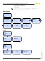
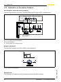
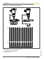
Block diagram, measured value processing
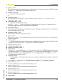
The following illustration shows the Transducer Block and Function block in simplified form.
Sensor mounting
correction
Sensor_Value
adjustment
bar
Linearization
%
Lin%
Temperature
TB
ALARMS
PVF-TIME
L-TYPE
Mode & Status
Simulate
DIRECT
Primary
Value
LOW-CUTOFF
Secondary
Value 2
OUT-SCALE
PV-SCALE
Secondary
Value 1
PV
Out
INDIRECT
ti
INDIRECT
SQRT
FIELD-VALUE
AI 2
AI 1
Channel = 1: Primary Value
Channel = 2: Secondary Value 1
Channel = 3: Secondary Value 2
Channel = 4: Temperature
AI 3
Fig. 28: Transducer Block VEGABAR 51
TB Transducer Block
AI Function Block (AI =Analogue Input)
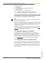
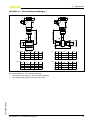
Diagram, adjustment
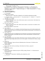
The following illustration shows the function of the adjustment:
Secondary_value_2
100 %
0%
scale_in_0 scale_in_100
scale_in_0
0
Sensor_value
scale_in_100
%
-0,500
0,500
100
%
bar
Fig. 29: Adjustment VEGABAR 51
62
VEGABAR 51 • Foundation Fieldbus
36715-EN-110629
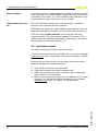
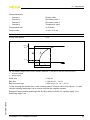
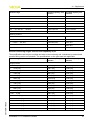
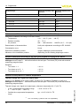
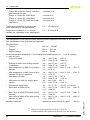
Parameter list
The following list contains the most important parameters and their meaning: