1
.
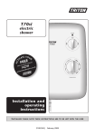
T450i electric show
er pump
.
Installation and Operating Instructions
INSTALLERS PLEASE NOTE THESE INSTRUCTIONS ARE TO BE LEFT WITH THE USER
2180150E Dec 2001
T450i
CONTENTS
Page
Plumbing and electrical notes
1
Introduction
2
Safety warnings
2
Key to main components
2
Site requirements
3
Siting of the pump
4
Fitting the pump
4–5
Variable speed control
6
Commissioning
6–7
Spare parts
8
Fault finding
9
Guarantee, service policy, etc.
rear cover
Due to continuous improvement and updating,
specification may be altered without prior notice.
Replacement parts can be ordered from Triton Customer
Service. See ‘spare parts’ for details.
UKAS
QUALITY
MANAGEMENT
003
T450i
1
PLUMBING NOTES
2
ELECTRICAL NOTES
1.1
All installations must comply with the Local
Water Company or Water Undertakers
Byelaws.
2.1
1.2
Supply pipe must be flushed thoroughly to
clear debris before connecting to the pump
and shower (Byelaw 55).
The installation must comply with BS 7671
‘Requirements for electrical installations’ (IEE
wiring regulations) and Electrical Supply
Company regulations. Ensure the incoming
cold water supply to the pump is adequately
earth bonded.
1.3
DO NOT connect the pump unit to the mains
cold water supply as it would damage the
unit and also, the installation would be in
breach of the guidance notes contained in
‘1’ above.
2.2
DO NOT turn on the electrical supply to the
pump until the plumbing connections have
been completed. The pump must not be
operated dry without water.
2.3
1.4
DO NOT use excessive force when making
connection to the flexible connector hose.
1.5
DO NOT turn on the electrical supply to the
pump until the plumbing connections and
commissioning procedure have been
completed. The pump must not be operated
dry without water.
The mains supply must be 230/240V, at
50Hz, connected to the pump via a double
pole switched 3 Amp fused connection unit
(not supplied) with a minimum 3mm contact
separation gap in each pole.
2.4
In accordance with ‘The Plugs and Sockets
etc. (Safety) Regulations 1994’, the pump is
intended to be permanently connected to
the fixed electrical wiring of the mains
system.
2.5
Fuses do not give personal protection
against electric shock.
2.6
It is strongly recommended to fit a 30mA
residual current device (RCD). This may be
part of the consumer unit or a separate unit.
1.6
DO NOT solder pipes or fittings within
300mm of the pump, as heat transfer can
damage the components.
1.7
A dedicated cold water supply must be
taken directly from the cold water cistern to
the pump. This draw-off must be on the
opposite side of the cistern to the float
operated valve.
1.8
Standard gate valve MUST be fitted on the
cold water supply to the pump as an
independent means of isolating the water
supplies should maintenance or servicing be
necessary. DO NOT use stop taps or ball-o-fix
type valves which restrict flow.
1.9
If the pump unit is installed on a common
supply which feeds an adjacent tap, the
maximum static inlet pressure for the unit
will, under certain circumstances be
exceeded. The action of closing the tap can
cause a pulse in the supply pressure which
may result in damage to the unit. This can
be resolved by the installation of a suitably
sized mini expansion vessel, sited as close as
possible to the tap and pressurised to 0.5
bar.
1
T450i
INTRODUCTION
Fig.1
This book contains all the necessary fitting and
operating instructions for your Triton T450i single
impeller shower pump.
Please read them carefully.
This product is rated at:
15 minutes on / 60 minutes off.
2
1
3
4
The shower pump has been designed for use with
stored cold water and is intended to be installed
with an instantaneous shower unit in areas subject
to low pressure.
The installation must be carried out by a suitably
competent person and in sequence of this
instruction book.
Care taken during the installation will ensure a
long and trouble free life from your unit.
Important: All plumbing connections must be
completed before making the electrical
connections.
Please read through the whole of this book before
beginning your installation.
5
SAFETY WARNINGS
a Under no circumstances must this pump be
connected to a mains cold water supply. Failure to
comply will invalidate the guarantee.
KEY TO MAIN COMPONENTS
(Fig.1)
b The shower pump MUST NOT be used if
suspected of being frozen.
1
Inlet connector hose
c
2
Outlet connector hose
3
Integral flow switch
d Switch off immediately at isolating switch if
water ceases to flow during use.
4
Variable speed control
5
PCB cover
This pump must be earthed.
e If it is intended to operate the unit outside the
guidelines laid out in ‘site requirements’.
f This pump is to be used for providing water to
a shower only.
In the interest of electrical safety a 30mA
residual current device (RCD) should be
installed in all UK electric and pumped shower
circuits. This may be part of the consumer unit
or a separate unit.
2
T450i
SITE REQUIREMENTS
Water
The installation must be in accordance with the
local Water Company Byelaws.
Cold
supply
For correct operation of this shower pump in
conjunction with the shower unit, the water must
be gravity fed from a cold water storage cistern.
Cold water cistern
Stop
valve
500 mm (20ins) min.
The cold water cistern must have a minimum
capacity of 114 litres (25 galls.) and a minimum
head of water of 500 mm (20ins).
The cold water supply to the pump must be direct
and separate from any other outlets or
connections.
Shower unit
THE PUMP MUST NOT BE CONNECTED TO THE
MAINS COLD WATER SUPPLY.
The pump must be positioned below the cold
water cistern and not placed in areas where it will
be subject to freezing conditions. Pipework must
be kept below the cistern water level.
To ensure correct operation of the flow switch, the
sprayhead must be at least 500 mm (20 ins.)
below the bottom of the cold water cistern. In
situations where this requirement cannot be met,
contact Triton Customer Service for advice.
Incoming
cold
water
mains
supply
Gate
valve
Pump
If used with a combination cylinder, the cold water
cistern must have a capacity of at least 114 litres
(25 galls.) to avoid starvation of water to the
pump.
Isolating switch
or pull cord switch
(both fused at 3A)
Fig.2 shows an installation option that is
acceptable.
NOTE: The supply from the cistern should be taken
from the opposite side to the float operated valve
to avoid air entering the pump supply.
Ring main
DO NOT use jointing compounds on any pipe
fittings.
Fig.2 Diagrammatic view (not to scale)
It is emphasised that this
pump is used for supplying
water to a shower only.
3
T450i
FITTING THE PUMP
Electrical
WARNING: THE PUMP MUST BE EARTHED.
The pump must be connected to a 230/240V A.C.
electrical supply from a ring main, via a double
pole switch with at least 3mm contact separation.
This can be a ceiling mounted pull cord switch in
the shower room, or a wall mounted switch in an
adjacent room.
The pump should be fused at 3 amps.
It is recommended that a suitable residual current
device (RCD) is fitted in the electricity supply circuit
to this appliance.
Before commencing installation of the pump,
ensure the site requirements have been fully
complied with.
Also, please note the following:
● Pipework to precede wiring.
● All pipework must be a minimum of
15mm diameter.
● The pump must be positioned in a dry area,
ideally in the linen/airing cupboard. It must be well
ventilated and not covered with towels and sheets
etc.
NOTE: The installation and wiring must comply
with current I.E.E. Regulations.
● Do not use with a combination water tank
system unless the cold water storage tank has
capacity of 114 litres (25 galls) or more.
When installed in any room containing a fixed
bath or shower, the pump MUST be located and
concealed inside a suitable cupboard, built-in unit
or other enclosure, so that the pump cannot be
sprayed with water, and such that a person using
a fixed bath or shower cannot touch the pump
without using tools.
DO NOT connect the pump electrical wiring to the
shower unit.
● To assist in clearing air bubbles from the system
avoid using sharp bends where possible.
Flexible/swept fittings or formed pipework is
recommended.
● Ensure that all water supplies are isolated before
connection. A gate valve or full way lever valve
must be fitted immediately prior to the pump. It is
also advisable to fit a drain-off point on the lowest
part of the system.
SITING OF THE PUMP
WARNING: THE UNIT MUST NOT BE POSITIONED
WHERE IT WILL BE SUBJECT TO FREEZING
CONDITIONS.
● NEVER use any form of soldered fittings on the
shower pump as this will damage the unit and
invalidate the guarantee.
The pump MUST ALWAYS be positioned BELOW
the cold water cistern.
It is recommended that the cold water supply is
taken from the opposite side of the cistern to the
ballcock feed to prevent air entrapment in the
supply.
Position the pump in a dry area and ensure it is
accessible for any maintenance etc. that may be
necessary.
● NEVER use solder within 300mm (12ins) of the
pump or expose parts to a hot torch.
● Ensure mains electricity supply is SWITCHED OFF
before commencing electrical connections.
● DO NOT OPERATE THE PUMP DRY.
NOTE: The pump motor has automatically
resetting thermal overload protection.
Procedure
a Turn off mains water and electrical supplies and
drain the cold water cistern.
Important: Ensure the ventilation slots on the
underside of the pump are free from obstructions.
b Position the pump horizontally (with the outlet
port vertical) with the feet on a solid base so that it
will not transmit vibration. NOTE: The pump MUST
ONLY be placed in the horizontal position.
4
T450i
c Connect the inlet flexible connector to the inlet
port of the pump ensuring the filter is in position
(fig.3).
d Connect the outlet flexible connector to the
outlet port of the pump.
e Connect the electric shower feed pipe to the
outlet flexible push-in connector.
f At this stage, DO NOT connect the cold water
supply from the cistern to the inlet flexible push-in
connector. Wait until the commissioning
procedure has been completed.
Filter
NOTE: Do not overtighten the connections on the
pump ports and take care to prevent any system
debris from entering the pump via the connectors.
Fig.3
Wiring
g Remove the four retaining screws holding the
PCB cover (fig.4). Lift the cover together with the
variable speed control from the pump body.
h The 3 core cable from the mains electricity
supply can now be connected to the terminal
block situated on the PCB (fig.5). The size of cable
to use must be a minimum of 0.75mm.
Retaining screw
Ensure the terminal block screws are fully
tightened and that no cable insulation is trapped
under the screws.
NOTE: When connecting the earth cable to the
earth post, take care NOT to overtighten the
securing nut.
Fig.4
Earth
post
L
LIVE
N
EARTH
NEUTRAL
Fig.5
5
T450i
Important: Remove only the minimum necessary
amount of conductor insulation when wiring to
the terminal block.
The cable clamp must be used to secure the cable
(fig.6).
Fig.6
Earth post
NOTE: Before replacing the cover, ensure the
potentiometer is rotated fully clockwise (fig.7)
until a ‘stop’ is felt. Then ensure the speed control
is positioned to ‘3’ on the cover (fig.8).
Replace the PCB cover and variable speed control
knob. Should the control knob have been
detached from the cover, ensure the ‘O’ ring
(fig.9) is correctly seated before replacing the
control knob.
WARNING: Installation of this pump will break the
earth continuity of the pipework installation. It is
important that the earth be restored by cross
bonding the pipework, in conformity with current
I.E.E. regulations.
Cable clamp
VARIABLE SPEED CONTROL
Fig.7
The variable speed control (fig.10) can be adjusted
to select the optimum performance of the pump
to suit personal preferences.
COMMISSIONING
Eart
post Before the first operation of the shower pump, it is
necessary to flush out any system debris from the
installation. This operation must be carried out
with the pump isolated from the electricity supply,
and with the pump feed pipework from the cistern
directed to waste by connecting a suitable length
of hose.
Fig.8
a Turn on the mains water supply to the storage
cistern and open the isolation valve to the pump
and allow the system to fill.
3
b Allow water to flow to waste for two or three
minutes to ensure any installation debris and air is
completely flushed from the system.
1
c Check the system pipework for leaks.
d Close the isolation valve to the pump.
e Remove the waste hose and connect the cistern
supply pipework to the pump inlet flexible push-in
connector. Re-open the isolation valve to the
pump.
2
SHOWER
f Switch on the mains electricity supply to the
electric shower unit and turn on the shower (refer
to the manufacturers instructions). Allow water to
6
T450i
flow under gravity from the sprayhead for a few
minutes.
Fig.9
g Check the pipework for any leaks.
h Turn off the shower at shower control.
j Switch on the mains electricity supply to the
pump.
k Start the shower again. The pump will operate
and water will flow. Allow water to flow to waste
for two or three minutes.
l Turn off the shower at shower control – the
pump will switch off and the water will cease to
flow.
'O' ring
m Switch off the electric supply to the pump and
eliminate any leaks.
NOTE: If care has been taken to prevent any
obvious debris entering the system, the above
procedure should be adequate for normal
operating conditions of the pump and shower.
However, it may be advisable to also clean the
filter in the inlet port of the pump as an extra
precaution.
Fig.10
3
1
2
SHOWER
BOOSTER
7
T450i
SPARE PARTS
Ref
2
3
1
4
5
7
6
Description
Part No.
1
Pump assembly
T450i00M
2
Cover
7052286
3
Impeller housing
7051544
4
Pump inlet
7051543
5
Speed control knob
7051552
6
End cap – blank
7052311
7
End cap
7052310
8
PCB assembly
7072314
9
Flow switch assembly
82300590
10
Flexible connector
inlet c/w filter
22004500
Flexible connector
outlet c/w filter
22004510
11
9
8
10
11
8
T450i
FAULT FINDING
Action/Cure
Problem/Symptom
Cause
1 Pump motor
does not operate.
1.1 Pump motor thermal
overload protection
activated.
1.1.1 Allow pump motor to cool and
automatically reset.
1.1.2 Check pump is adequately ventilated.
1.2 Mains electricity
supply fault.
1.2.1 Blown fuse. Check supply, and renew or
reset fuse. If it fails again, contact Customer
Service.
1.2.2 Power cut. Check other appliances and if
necessary contact local electricity Company.
1.3 Loose wiring
connections.
1.3.1 Check all connections and secure where
necessary.
1.4 Insufficient flow to
operate flow switch.
1.4.1 Check isolating valve is fully open.
1.4.2 Check head of water.
1.4.3 Ensure inlet filter is clean.
1.5 Faulty flow switch.
1.5.1 Replace switch. Contact Triton Customer
Service for advice.
1.6 Failed pump motor
1.6.1 Replace pump unit. Contact Triton
Customer Service.
2.1 Pump motor not
running.
2.1.1 See causes 1.1, 1.2, 1.3, 1.4, 1.5, and 1.6
2.2 Pump or shower unit
frozen.
2.2.1 Check for evidence of freezing. Contact
Triton Customer Service for advice.
2.3 Water turned off.
2.3.1 Check isolation valve and water supply.
2.4 No water in cold
storage cistern.
2.4.1 See 2.3.1
2.5 Blocked flow switch.
2.5.1 Remove obstruction and flush out
thoroughly.
2.6 Blocked sprayhead
on shower unit.
2.6.1 Clean sprayhead. Refer to separate
instructions.
2.7 Blocked filter.
2.7.1 Clean filter.
3.1 Faulty flow switch
3.1.1 Replace flow switch. Isolate electric supply
to pump. Contact Triton Customer Service for
advice.
2 Poor or no water
flow.
3 Pump does not
switch off.
Any maintenance or repair to the pump MUST be carried out by a suitably competent person
9
Service Policy
Triton Standard Guarantee
In the event of a complaint occurring, the following
procedure should be followed:
1 Telephone Customer Service on:
0870 067 3333 (0845 762 6591 in Scotland and
in Northern Ireland), having available the model
number and power rating of the product, together
with the date of purchase.
2 Triton Customer Service will be able to confirm
whether the fault can be rectified by either the
provision of a replacement part or a site visit
from a qualified Triton service engineer.
3 If a service call is required the unit must be fully
installed for the call to be booked and the date
confirmed. In order to speed up your request,
please have your postcode available when
booking a service call.
4 It is essential that you or an appointed representative (who must be a person of 18 years of age or
more) is present during the service engineer's visit
and receipt of purchase is shown.
5 A charge will be made in the event of an aborted
service call by you but not by us, or where a call
under the terms of guarantee has been booked and
the failure is not product related (i.e. scaling and
furring, incorrect water pressure, pressure relief
device operation, electrical installation faults).
6 If the product is no longer covered by the
guarantee, a charge will be made for the site
visit and for any parts supplied.
7 Service charges are based on the account being
settled when work is complete, the engineer
will then request payment for the invoice. If this
is not made to the service engineer or settled
within ten working days, an administration
charge will be added.
Triton guarantee this product against all
mechanical and electrical defects arising from faulty
workmanship or materials for a period of one year
for domestic use only, from the date of purchase,
provided that it has been installed by a competent
person in full accordance with the
fitting instructions.
Any part found to be defective during this
guarantee period we undertake to repair or replace
at our option without charge so long as it has been
properly maintained and operated in accordance
with the operating instructions, and has not been
subject to misuse or damage.
This product must not be taken apart, modified or
repaired except by a person authorised by Triton.
This guarantee applies only to products installed
within the United Kingdom and does not apply to
products used commercially. This guarantee does
not affect your statutory rights.
Replacement Parts Policy
Availability: It is the policy of Triton to maintain
availability of parts for the current range of
products for supply after the guarantee has
expired. Stocks of spare parts will be maintained
for the duration of the product’s manufacture and
for a period of five years thereafter.
In the event of a spare part not being available a
substitute part will be supplied.
Payment: The following payment methods can be
used to obtain spare parts:
1 By post, pre-payment of pro forma invoice by
cheque or money order.
2 By telephone, quoting credit card (MasterCard
or Visa) details.
3 By website order, www.tritonshowers.co.uk
Triton Showers
Triton Road
Nuneaton
Warwickshire CV11 4NR
Triton is a division of Norcros Group (Holdings) Limited
What is not covered:
1 Breakdown due to: a) use other than domestic
use by you or your resident family;
b) wilful act or neglect; c) any malfunction
resulting from the incorrect use or quality of
electricity, gas or water or incorrect setting of
controls; d) faulty installation.
2 Repair costs for damage caused by foreign
objects or substances.
3 Total loss of the product due to non-availability
of parts.
4 Compensation for loss of use of the product or
consequential loss of any kind.
5 Call out charges where no fault has been found
with the appliance.
6 The cost of repair or replacement of pressure relief
devices, showerheads, hoses, riser rails and/or wall
brackets, isolating switches, electrical cable, fuses
and/or circuit breakers or any other accessories
installed at the same time.
7 The cost of routine maintenance, adjustments,
overhaul modifications or loss or damage arising
therefrom, including the cost of repairing
damage, breakdown, malfunction caused by
corrosion, furring, pipe scaling, limescale, system
debris or frost.
Customer Service:
% 0870 067 3333
Scottish and Northern Ireland
Customer Service:
0845 762 6591
%
%
Trade Installer Hotline:
0870 067 3767
Fax: 0870 067 3334
www.tritonshowers.co.uk
E mail: [email protected]
Extended Warranty AVAILABLE NOW. Call 0870 067 3333 for more details.
TRITON reserve the right to change product specification without prior notice. E&OA. © TRITON SHOWERS 2008