1
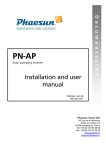
B
IDENTIFICATION OF ELECTRICAL SYSTEM FAILURES
CNK 50 DRAKON
WORKSHOP MANUALS
INDEX
IDENTIFICATION OF ELECTRICAL
SYSTEM FAILURES
DRAKON 50 NKD
INDEX
1-
1
B
1 - INDEX. ..............................................................................................................................
3
2 - ELECTRICAL SYSTEM. ...................................................................................................
4
ELECTRICAL SYSTEM CODE ....................................................................................................
5
3 - ELECTRICAL COMPONENTS. ........................................................................................
6
4 - CHECKING THE CONNECTIONS. ...................................................................................
8
5 - CHECKING THE SWITCHES. ...........................................................................................
9
SWITCH CONNECTIONS AS SHOWN IN THIS MANUAL ..........................................................
9
6 - IGNITION SYSTEM. .......................................................................................................... 10
7 - ELECTRICAL STARTING SYSTEM . ............................................................................... 13
STARTING CIRCUIT OPERATION .............................................................................................. 13
8 - RECHARGE SYSTEM. ..................................................................................................... 18
TROUBLE SHOOTING ................................................................................................................. 18
9 - LIGHTS SYSTEM.............................................................................................................. 20
TROUBLE SHOOTING ................................................................................................................. 20
LIGHTING SYSTEM CHECK ........................................................................................................ 22
10 - SIGNAL SYSTEM. ............................................................................................................ 24
TROUBLE SHOOTING ................................................................................................................. 24
CHECKING THE SIGNAL SYSTEM ............................................................................................. 26
CONFIGURATION OF THE DIGITAL INSTRUMENT CONNECTOR .......................................... 42
3
03/06
2-
ELECTRI-
B
IDENTIFICATION OF ELECTRICAL
SYSTEM FAILURES
2
ELECTRICAL SYSTEM
6
17
12
DRAKON 50 NKD
14
9
36
B/R
8
-
+
B/R
31
M
BL
N
BL
VR
M
VR
M
VL
AR
VL
AR
BL
AZ
L
M
33
VL
0FF
ON
HORN
AR
AZ
32
R
VL
VR
N
R
30
29
1Kohm
B-BL
N
B-BL B-BL
N
N
VR
TURN
N
B-R
RELAIS
R
BL
R
RS
BL
BL
RS
B/N
RS
34
R
VL
HI
G
BL
VR
OFF
LO
GL VL-GL
A
B/BL
R
18
19
ON
R
B
VR
B-N
FUSE 10A
MODE
N
AR
K
7
11
AZ
35
B/BL B/BL
10
G
B-N
N
B-N
RS
RS
N
N
28
RS
B-N
24
N
GL
20
R
BL RS
N
N
22
N
21
R
N
VR
VR
R
VR
26
VR
18
13
NEUTRAL
4
BL - N
GL-VR
BL - R
B-VR
N
B -MA
BL
B-VR
3
BL-B
N
B-N
B
1
GR
B
R
GL-R
B/N
R-N
VL
AZ-B
GR
GL-VR
N
VR
1
16
LOCK
OFF
ON
N
GL
VL-GL
B-N
B-R
N
BL
BL
AR
BL-R
B-R
BL
AR
VR
GL
VR-N
VR
GL
GL
RS
VR-N
BL
^
BL
03/06
R
BL
24
05188053
4
OFF
R
BL - N
GL-V
GL - R
23
START
B-R
BL
ON
25
5
2
R
15
IDENTIFICATION OF ELECTRICAL
SYSTEM FAILURES
ELECTRICAL SYSTEM CODE
1)
2)
3)
4)
5)
6)
7)
8)
9)
10)
11)
12)
13)
14)
15)
16)
17)
18)
19)
20)
21)
22)
23)
24)
25)
26)
27)
28)
29)
30)
31)
32)
33)
34)
35)
36)
2
ELECTRICAL SYSTEM
DRAKON 50 NKD
B
COLOUR CODE
AR
AZ
AZ-B
B
B-N
B-MA
B-R
B-VR
BL
BL-B
BL-N
BL-R
GL
GL-B
GL-N
GL-R
GL-VR
GR
M
N
R
RS
VL
VR
VL-GL
Instrument panel
Main switch
Oil gauge indicator switch
Neutral gear switch
Regulator
Battery
Fuse 10A
Clutch switch
Flasher unit
Starting relay
Rear stop switch
“CDI” control unit
Water temperature probe
Horn
Front stop switch
Fuel reserve sensor
CDI magneto
Starter
Left rear flasher light
Tail brake and stop light
Right rear flasher light
Electrical earth of the engine
Tachometer counter
Right control unit
Starter button
Right front flasher light
High beam
Parking light
Low beam
Left front flasher light
Left control unit
Horn control
Flasher light control
Light control
MODE button
Chassis ground
5
03/06
Orange
Light blue
Light blue-White
White
White - Black
White - Brown
White - Red
White - Green
Blue
Blue - White
Blue - Black
Blue - Red
Yellow
Yellow - White
Yellow - Black
Yellow - Red
Yellow - Green
Grey
Brown
Black
Red
Pink
Purple
Green
Purple - Yellow
3-
ELECTRI-
B
1)
2)
3)
4)
5)
6)
7)
8)
3
IDENTIFICATION OF ELECTRICAL
SYSTEM FAILURES
COMPONENTI ELETTRICI
ELECTRICAL COMPONENTS
DRAKON 50 NKD
Digital meter assembly
Main switch
Oil gauge indicator switch
Neutral gear switch
Regulator
Battery
Fuse 10A
Clutch switch
7
1
8
6
2
05188001
05188005
05188006
05188091
4
3
5
05188002
05188003
05188004
6
03/06
IDENTIFICATION OF ELECTRICAL
SYSTEM FAILURES
9)
10)
11)
12)
13)
14)
15)
16)
3
ELECTRICAL COMPONENTS
DRAKON 50 NKD
B
Flasher unit
Starting relay
Rear stop switch
“CDI” control unit
Water temperature probe
Horn
Front stop switch
Fuel level gauge
9
15
16
10
05188007
05188012
05188006
14
05188011
05188090
12
11
05188008
13
05188009
05188010
7
03/06
IDENTIFICATION OF ELECTRICAL
SYSTEM FAILURES
B
4
CHECKING THE CONNECTIONS
4-
CHECKING THE CONNECTIONS
DRAKON 50 NKD
Check rust and moisture of connectors.
1) Disconnect
• Connectors
2) Dry each terminal with an air blower.
05188013
3) Connect and disconnect the connector twice or three
times.
4) Pull the connector to check that it will not come off.
5) If the terminal comes off, bend up pin (A) and reinsert
the terminal into the connector.
A
05188014
6) Connect
• Connectors
NOTE
The connector parts are assembled properly when they
“click” together.
05188015
7) Check for continuity with a Tester.
NOTE
• If there is no continuity, clean the terminals.
• Be sure to perform the steps 1 to 7 when checking the
electrical system.
• For a field remedy, use a contact revitalizer.
• Use the Tester as shown in figure.
05188016
8
03/06
CHECKING THE SWITCHES
IDENTIFICATION OF ELECTRICAL
SYSTEM FAILURES
CHECKING
THE SWITCHES
ELECTRICAL
SYSTEM
DRAKON 50 NKD
• Set the Tester selector to “ ”.
• Insert the terminals of the tester in the connector
corresponding to the cables in question.
• Check continuity.
05188017
SWITCH CONNECTIONS AS SHOWN
IN THIS MANUAL
This manual contains the connection charts (as shown
left) showing the switch terminals (e.g., main switch, brake
switch, lighting switch, etc.)
The left column indicates the different switch positions;
the top line indicates the colours of the conductors connected to the switch terminals.
“
” indicates the continuity between terminals; i.e., a
closed circuit at the special switch positions.
In this chart, “BL” and “R” are continuous when the switch
is set to “ON”.
RIGHT-HAND CONTROL
05188018
5-
9
03/06
5
B
6-
IGNITION
B
IDENTIFICATION OF ELECTRICAL
SYSTEM FAILURES
6
IGNITION SYSTEM
DRAKON 50 NKD
THE IGNITION SYSTEM FAILS TO OPERATE
(NO SPARK OR INTERMITTENT SPARK)
Check
1) Spark plug
2) Spark plug cap resistance
3) ”CDI” control unit resistance
4) Main switch
5) Resistance of condenser charging coil
6) Pick-up resistance
7) Ignition system connections
1 Spark plug
Standard spark plug:
NGK BR 9ES
• Check the spark plug conditions
• Check the spark plug type
• Check the electrode gap
INCORRECT
Electrode gap:
0,7 mm
CORRECT
Faulty spark plug ➜
Replace or adjust the electrode gap
2 Spark plug cap resistance
• Remove the spark plug cap
NOTE
Removing the spark plug ➜ Rotate the cap anticlockwise
Installing the spark plug ➜ Turn the key clockwise.
2
• Connect Tester (k ) as follows:
- Terminal (+) Tester ➜ side 1
- Terminal (-) Tester ➜ side 2
1
Cap resistance:
5K ± 20% a 20°C
INCORRECT
CORRECT
Faulty spark plug cap ➜ Replace
05188060
10
03/06
IDENTIFICATION OF ELECTRICAL
SYSTEM FAILURES
6
IGNITION SYSTEM
DRAKON 50 NKD
3 ”CDI” control unit resistance
• Connect the Tester (k ) to the control unit as
follows:
- Terminal (+) Tester ➜ Cable A.T. (1)
- Terminal (-) Tester ➜ cable terminal (2)
1
2
Secondary coil resistance:
5-6 K a 20 °C.
INCORRECT
CORRECT
“CDI” control unit faulty ➜ Replace
4 Main switch
• Disconnect the main switch from the system
• Connect the Tester ( ) and check the continuity
between the following cables:
• Turn the main switch to “ON”
- Orange (1) ➜ Green (2)
- Yellow (3) ➜ Green - Black (4)
• Turn the main switch to “OFF”
• Check the continuity between the following cables:
- Blue - Red (5) ➜ Blue (6)
5
6
1
2
3
INCORRECT
See “Checking the switches” page 7
CORRECT
Faulty main switch ➜ Replace
05188061
11
03/06
4
B
IDENTIFICATION OF ELECTRICAL
SYSTEM FAILURES
B
6
IGNITION SYSTEM
DRAKON 50 NKD
5 Resistance of condenser charging coil
• Disconnect flywheel connectors
• Connect Tester ( ) as follows:
- Terminal (+) Tester ➜ Green cable (1)
- Terminal (-) Tester ➜ White cable (2)
1
2
Charge coil resistance:
640-780 a 20 °C.
INCORRECT
CORRECT
Replace the yoke
6 Pick-up resistance
• Connect the Tester ( ) to the flywheel as follows:
- Terminal (+) Tester ➜ Red cable (1)
- Terminal (-) Tester ➜ White cable (2)
1
2
Pick-up resistance
100-140 a 20 °C.
INCORRECT
CORRECT
Replace the yoke
7 Wiring connections
• Check the ignition system for connections
See “Electrical diagram”
INCORRECT
Repair the system wiring
05188060
12
03/06
7-
ELECTRICAL STARTING SYSTEM
DRAKON 50 NKD
IDENTIFICATION OF ELECTRICAL
SYSTEM FAILURES
ELECTRICAL STARTING SYSTEM
B
7
STARTING CIRCUIT OPERATION
2
The starting circuit on this model consists of the starter
motor and the starter relay.
When the main switch is in “ON” position and the starting
button is pressed, the starter motor can operate only if:
3
1
4
8
5
THE CLUTCH HANDLE IS PULLED
If the above mentioned conditions are not met, the starting relay cannot be energized.
BL
1)
2)
3)
4)
5)
6)
7)
8)
B/R
Battery
Fuse 10A
Main switch
Starting switch (start)
Clutch switch
Starting relay
Starter
Chassis ground
6
8
BL
7
8
05188024
13
03/06
IDENTIFICATION OF ELECTRICAL
SYSTEM FAILURES
B
7
ELECTRICAL STARTING SYSTEM
DRAKON 50 NKD
THE STARTER MOTOR FAILS TO OPERATE
Check
1) Fuse 10A
2) Battery
3) Starter
4) Starting relay
5) Main switch
6) Clutch switch
7) Starting switch (start)
8) Wiring connections
1 Fuse 10A
• Remove the fuse
• Connect Tester ( ) to the fuse
• Check the fuse for continuity
NO CONTINUITY
CONTINUITY
Faulty fuse ➜ Replace
2 Battery
• Check the battery conditions
See “Charge voltage” on page 16
Minimum voltage: 12,5 V
Specific gravity electrolyte level:
1.280 g/dm3
INCORRECT
CORRECT
Clean the terminals
Recharge or replace battery
05188063
14
03/06
IDENTIFICATION OF ELECTRICAL
SYSTEM FAILURES
ELECTRICAL STARTING SYSTEM
DRAKON 50 NKD
3 Starter
3
B
WARNING
A wire for the jumper lead must have the equivalent
capacity as that of the battery lead or more, otherwise it may cause the jumper lead to be burned.
• Connect battery positive terminal (1) and starter
motor cable (2) using a jumper lead (3) as shown in
figure.
(4) Starting relay
2
7
1
4
THE STARTER MOTOR
FAILS TO TURN
• Check the starter motor for operation.
THE STARTER MOTOR TURNS
Faulty starter motor ➜ Replace
WARNING
• Take care not to reverse the battery connections
because the diode will be damaged.
4 Starting relay
• Disconnect the starter relay
• Connect the battery to the starting relay with jumper
leads (1).
Battery cable (+) ➜ White - Red cable
Battery cable (-) ➜ Black cable
• Take care to avoid shorting the positive and negative terminals when connecting the battery to the
relay.
1
THE STARTER MOTOR
FAILS TO TURN
• Check the starter motor for operation.
THE STARTER MOTOR TURNS
Faulty starter motor ➜ Replace
05188064
15
03/06
IDENTIFICATION OF ELECTRICAL
SYSTEM FAILURES
B
7
ELECTRICAL STARTING SYSTEM
DRAKON 50 NKD
5 Main switch
• Disconnect the main switch
• Turn the main switch to “ON”
• Connect Tester ( ) and check leads for continuity
Orange cable ➜ Green cable
Yellow lead ➜ Green-Black lead
See “Checking the switches” page 7
INCORRECT
CORRECT
Faulty main switch ➜ Replace
6 Clutch switch
• Disconnect clutch switch (1)
• Connect Tester ( ) and check the terminals for
continuity.
Terminal (T1) ➜ Terminal (T2)
See “Checking the switches” page 7
1
1 Clutch lever not
pulled
2 Clutch lever pulled
INCORRECT
CORRECT
Faulty clutch switch ➜ Replace
05188065
16
03/06
IDENTIFICATION OF ELECTRICAL
SYSTEM FAILURES
ELECTRICAL STARTING SYSTEM
DRAKON 50 NKD
7
7 Starting switch (start)
• Disconnect two-way connector (1)
• Connect the Tester ( ) to the connector on the side
of the switch
Terminal (+) Tester ➜ Red cable (2)
Terminal (-) Tester ➜ Blue cable (3)
• Press the “START” button
2
1
NO CONTINUITY
3
CONTINUITY
Faulty starting switch ➜ Replace
8 Wiring connections
• Check the ignition system for connections
INCORRECT
Reset see “Electrical diagram”
05188066
17
03/06
B
8-
IDENTIFICATION OF ELECTRICAL
SYSTEM FAILURES
RE-
B
8
RECHARGE SYSTEM
DRAKON 50 NKD
TROUBLE SHOOTING
IF THE BATTERY IS FLAT
Check
1) Fuse 10A
2) Charge voltage
3) Charge coil resistance
4) Recharge system connections
1 Fuse 10A
• Remove the fuse
• Connect Tester ( ) to the fuse
• Check the fuse for continuity
NO CONTINUITY
CONTINUITY
Faulty fuse ➜ Replace
2 Charge voltage
• Connect the inductive rev counter to the spark plug
cable.
• Connect the Tester (DC 20 V) to the battery
Terminal (+) ➜ Terminal (+) of the battery
Terminal (-) ➜ Terminal (-) of the battery
• Measure the battery voltage
• Start the engine and accelerate to 5000 rpm.
• Check the battery voltage
Charge voltage:
13,5 ~ 14,5 V
NOTE
Use a completely charged battery.
CORRECT
INCORRECT
The charging circuit operates properly
05188067
18
03/06
IDENTIFICATION OF ELECTRICAL
SYSTEM FAILURES
RECHARGE SYSTEM
DRAKON 50 NKD
3 Charge coil resistance
• Disconnect flywheel connectors
• Connect Tester ( ) as follows:
Terminal (+) ➜ Terminal of yellow cable (1)
Terminal (-) ➜ Terminal of white cable (2)
1
2
INCORRECT
Charge coil resistance:
0,2 ~0,7 a 20 °C
CORRECT
Replace the yoke
4 Recharge system connections
• Check the connections of the recharge system
See “Electrical diagram”
INCORRECT
CORRECT
Repair the system wiring
Replace the voltage regulator
05188068
19
03/06
8
B
9-
LIGHTS
B
IDENTIFICATION OF ELECTRICAL
SYSTEM FAILURES
9
LIGHTS SYSTEM
DRAKON 50 NKD
TROUBLE SHOOTING
LIGHTS SYSTEM FAULTY
Check
1) Lighting coil resistance
2) Voltage regulator
3) Main switch
4) Lighting system wiring
1 Lighting coil resistance
• Disconnect flywheel connectors.
• Connect Tester ( ) as follows:
Terminal (+) ➜ Yellow lead terminal (1)
Terminal (-) ➜ White lead terminal (2)
2
1
Lighting coil resistance:
0,2~0,7
INCORRECT
a 20 °C
CORRECT
Replace the yoke
05188069
20
03/06
IDENTIFICATION OF ELECTRICAL
SYSTEM FAILURES
LIGHTS SYSTEM
DRAKON 50 NKD
2 Check voltage regulator
• Connect the Tester (AC) to the connector of the
regulator (leaving it inserted).
Terminal (+) Tester ➜ Purple - yellow cable (1)
Terminal (-) Tester ➜ Black lead (2)
• Start the engine at 5000 rpm.
• The voltage measured should be > 12 V.
2
1
INCORRECT
CORRECT
Replace the voltage regulator
3 Main switch
• Disconnect the main switch
• Turn the main switch to “ON”
• Connect the Tester ( ) and check the continuity
between the following cables:
Yellow lead ➜ Green-black lead
See “Checking the switches” page 7.
INCORRECT
CORRECT
Replace the main switch
4 Lighting system wiring
• Check all connections of the lighting system
See “Electrical diagram”
INCORRECT
Repair the system wiring
05188070
21
03/06
9
B
IDENTIFICATION OF ELECTRICAL
SYSTEM FAILURES
B
9
LIGHTS SYSTEM
DRAKON 50 NKD
LIGHTING SYSTEM CHECK
THE LOW BEAM, HIGH BEAM
AND HIGH BEAM INDICATOR DO NOT COME ON
1 Bulb and bulb socket
• Check the bulb and bulb socket for continuity
NO CONTINUITY
CONTINUITY
Replace bulb or bulb socket
2 Checking the light holder and meter
assembly voltage
A
B
• Connect the Tester (AC 20 V) to the connector of
the headlight and the digital instrument.
(A) Checking the low beam indicator light
Terminal (+) ➜ Blue-white lead
Terminal (-) ➜ Black lead
C
(B) Checking the high beam indicator light
Terminal (+) ➜ White-black lead
Terminal (-) ➜ Black lead
PIN 4
(C) High beam indicator check
Terminal (+) ➜ White-black lead (PIN 4)
Terminal (-) ➜ Black lead (PIN 13)
• Start the engine and press the button to activate the
high and low beam indicator lights.
• The voltage measured by the tests (A-B-C)
should be > 12 V.
PIN 13
INCORRECT
CORRECT
Repair the connections of the front headlight
and the meter assembly light.
See “Electrical diagram”
The circuit is not faulty
05188071
22
03/06
IDENTIFICATION OF ELECTRICAL
SYSTEM FAILURES
LIGHTS SYSTEM
DRAKON 50 NKD
9
B
THE TAILLIGHT FAILS TO COME ON
1 Bulb and bulb socket
• Check the bulb and bulb socket for continuity
NO CONTINUITY
CONTINUITY
Replace bulb or bulb socket
2 Checking the light holder voltage
• Connect Tester AC 20V to the bulb socket terminals.
Terminal (+) ➜ Pink lead terminal
Terminal (-) ➜ Black lead terminal
• Start the engine at 5000 rpm.
• The voltage measured should be > 12 V.
INCORRECT
CORRECT
Restore the connections between the main switch
and the rear light.
See “Electrical diagram”
The circuit is not faulty
05188072
23
03/06
10 -
SIGNAL
B
IDENTIFICATION OF ELECTRICAL
SYSTEM FAILURES
10
SIGNAL SYSTEM
DRAKON 50 NKD
TROUBLE SHOOTING
THE TURN INDICATORS, STOP LIGHT AND INSTRUMENT PANEL LIGHTS DO NOT COME ON;
THE REV COUNTER AND HORN DO NOT WORK
Check
1) Fuse 10A
2) Battery
3) Main switch
4) Signal system wiring
1 Fuse 10A
• Remove the fuse
• Connect Tester ( ) to the fuse
• Check the fuse for continuity
NO CONTINUITY
CONTINUITY
Faulty fuse ➜ Replace
2 Battery
• Check the battery conditions
Minimum voltage: 12,5V
Specific gravity electrolyte level:
1.280 g/dm3
Electrolyte level
INCORRECT
CORRECT
Clean the terminals
Recharge or replace battery
Refill with distilled water
05188073
24
03/06
IDENTIFICATION OF ELECTRICAL
SYSTEM FAILURES
SIGNAL SYSTEM
DRAKON 50 NKD
10
3 Main switch
• Disconnect connector (1) of the main switch
• Turn the main switch to “ON”
• Connect Tester ( ) and check the continuity as
follows:
Terminal (+) ➜ Orange lead (2)
Terminal (-) ➜ Green lead (3)
Terminal (+) ➜ Yellow lead (4)
Terminal (-) ➜ Green-black lead (5)
See “Checking the connections” page 6
5
2
1
INCORRECT
3
4
CORRECT
Faulty main switch ➜ Replace
4 Check wiring
• Check the signal system wiring
See “Electrical diagram”
INCORRECT
CORRECT
Repair the system wiring
• Check the conditions of all signal system circuits
See “Checking the signal system” page 24
05188074
25
03/06
B
IDENTIFICATION OF ELECTRICAL
SYSTEM FAILURES
B
10
SIGNAL SYSTEM
DRAKON 50 NKD
CHECKING THE SIGNAL SYSTEM
THE HORN DOES NOT WORK
1 Horn switch
• Disconnect the nine core connector of the left side
switch.
• Connect Tester ( ) to the connector
• Press the button (Horn) to activate the horn
• Check continuity between the cables as follows:
Terminal (+) ➜ Orange lead (1)
Terminal (-) ➜ Light blue lead (2)
Button pressed ➜ Continuity
Button not pressed ➜ No continuity
INCORRECT
1
2
CORRECT
Horn switch faulty ➜ Replace the left switch.
05188075
26
03/06
IDENTIFICATION OF ELECTRICAL
SYSTEM FAILURES
10
SIGNAL SYSTEM
DRAKON 50 NKD
B
2 Power supply check
1
• Connect Tester (DC 20 V) as follows:
Terminal (+) ➜ Orange lead (1)
Terminal (-) ➜ Chassis ground (2)
• Turn the main switch to “ON”
• Press the button (Horn) to activate the horn
2
INCORRECT
• The voltage measured should be > 12 V.
CORRECT
Restore the connection
of the feed circuit of the horn.
See “Electrical diagram”
3 Ground check
• Disconnect the black lead from the terminal of horn
• Make a bridge (1), between the terminal (2) and the
frame’s electrical earth (3).
• Turn the main switch to “ON”
• Press the button (Horn) to activate the horn
12 V
1
2
THE HORN SOUNDS
3
THE HORN
DOES NOT SOUND
Repair the connection
between the black lead and the chassis ground
See “Electrical diagram”
Faulty horn ➜ Replace
05188076
27
03/06
IDENTIFICATION OF ELECTRICAL
SYSTEM FAILURES
B
10
SIGNAL SYSTEM
DRAKON 50 NKD
THE STOP LIGHT FAILS TO COME ON
1 Bulb and bulb socket
• Check the bulb and bulb socket for continuity
NO CONTINUITY
CONTINUITY
Replace bulb or bulb socket
2 Front and rear brake switch
• Disconnect the switch leads
• Connect Tester ( ) to terminals (T1-T2)
• Check the terminals for continuity
See "Checking the switches" page 7
1) Front brake lever
pulled
2) Front brake lever not
pulled
A
B
1) Rear brake pedal
pressed
2) Rear brake pedal not
pressed
(A) Front brake switch
(B) Rear brake switch
INCORRECT
CORRECT
Faulty brake switch ➜ Replace
05188077
28
03/06
IDENTIFICATION OF ELECTRICAL
SYSTEM FAILURES
SIGNAL SYSTEM
DRAKON 50 NKD
10
3 Voltage check
• Connect Tester (DC 20V) to the bulb socket
connector
Terminal (+) ➜ Red lead (1)
Terminal (-) ➜ Black lead (2)
1
2
• Turn the main switch to “ON”
• Pull the rear brake lever or press the rear brake
pedal.
• The measured voltage in both cases must be
12 V
INCORRECT
CORRECT
Faulty read lead, repair wiring
See “Electrical diagram”
The circuit is not faulty
05188078
29
03/06
B
IDENTIFICATION OF ELECTRICAL
SYSTEM FAILURES
B
10
SIGNAL SYSTEM
DRAKON 50 NKD
THE TURN INDICATORS AND THEIR INDICATOR PANEL LIGHTS DO NOT WORK
1 Bulb and bulb socket
• Check the bulb and bulb socket for continuity
NO CONTINUITY
CONTINUITY
Replace bulb or bulb socket
2 Turn indicator switch.
• Disconnect the nine core connector of the left side
switch.
• Connect the Tester ( ) to the cables, as follows:
• Switch on the right turn indicators.
Terminal (+) ➜ Brown lead (1)
Terminal (-) ➜ Green lead (2)
• Switch on the left turn indicators.
Terminal (+) ➜ Brown lead (1)
Terminal (-) ➜ Purple lead (3)
• In both cases there must be continuity.
2
1
3
INCORRECT
CORRECT
Faulty flasher light switch ➜
Replace the left switch.
05188079
30
03/06
IDENTIFICATION OF ELECTRICAL
SYSTEM FAILURES
SIGNAL SYSTEM
DRAKON 50 NKD
10
3 Flasher relay voltage check
• Disconnect connector of flasher relay
• Connect Tester (DC 20 V) as follows:
Terminal (+) ➜ Blue lead (1)
Terminal (-) ➜ Chassis ground (2)
1
2
• Turn the main switch to “ON”
• The voltage measured should be > 12 V.
INCORRECT
CORRECT
Faulty blue lead between main switch
and flasher relay.
See “Electrical diagram”
4 Check the brown lead for continuity
• Disconnect connector of flasher relay
• Disconnect connector of the left control unit
• Connect Tester Tester ( ) to the terminals of the
different connectors
• Check the brown lead for continuity
NO CONTINUITY
CONTINUITY
Faulty brown lead between flasher relay
and left control unit.
Repair wiring.
See “Electrical diagram”
Faulty flasher relay ➜ Replace
05188080
31
03/06
B
IDENTIFICATION OF ELECTRICAL
SYSTEM FAILURES
B
10
SIGNAL SYSTEM
DRAKON 50 NKD
5 Check voltage of right and left light holder
• Connect Tester (DC 20V) to the bulb socket
connector
(A) Left flasher light
Terminal (+) ➜ Purple lead (1)
Terminal (-) ➜ Chassis ground (3)
(B) Right flasher light
Terminal (+) ➜ Green lead (2)
Terminal (-) ➜ Chassis ground (3)
1
•
•
•
•
2
Turn the main switch to “ON”
(A) Use the switch to activate the left flasher lights
(B) Use the switch to activate the right flasher lights
The voltage measured, in both cases, should
be > 12 V.
INCORRECT
CORRECT
Cables interrupted between the turn indicator switch
and the connector of the bulb socket.
Repair wiring.
See “Electrical diagram”
The circuit is not faulty
05188081
32
03/06
IDENTIFICATION OF ELECTRICAL
SYSTEM FAILURES
SIGNAL SYSTEM
DRAKON 50 NKD
10
NEUTRAL GEAR INDICATOR COMES ON ONLY WITH “CHECK”
1 Neutral switch check
• Connect Tester ( ) and check the continuity
between the neutral switch and the ground
Neutral switch (1) ➜ Chassis ground (2)
Gears in neutral ➜ Continuity
Engaged gear ➜ No continuity
2
1
INCORRECT
CORRECT
Faulty neutral switch ➜ Replace
05188082
33
03/06
B
IDENTIFICATION OF ELECTRICAL
SYSTEM FAILURES
B
10
SIGNAL SYSTEM
2 Meter assembly check
DRAKON 50 NKD
WARNING
After disassembling the cable terminal, check
that the neutral switch is tightened properly.
• Disconnect connector of meter assembly (1)
• Disconnect cable terminal (2) of neutral switch
• Connect Tester ( ) as follows:
Terminal (+) ➜ Red cable terminal /black (2)
Terminal (-) ➜ Red-black lead (PIN 3)
R/N
1
3
NO CONTINUITY
2
CONTINUITY
Faulty lead between neutral switch and meter
assembly connector. Repair wiring.
See “Electrical diagram”
Reduce the excessive play of the faston
inserted in the PIN 3 of the instrument panel
connector (red – black cable).
NOTE
If the warning light does not even come on doing the “CHECK”, replace the digital instrument.
05188083
34
03/06
IDENTIFICATION OF ELECTRICAL
SYSTEM FAILURES
SIGNAL SYSTEM
DRAKON 50 NKD
WHEN THE “MODE” BUTTON IS PRESSED,
THE DISPLAY DOES NOT CHANGE FUNCTION
1 “Mode” button check
• Disconnect the nine core connector of the left side
switch.
• Connect Tester ( ) as follows:
Terminal (+) ➜ Yellow lead (1)
Terminal (-) ➜ Light blue lead (2)
• Press the “Mode” button
• Check continuity.
1
2
NO CONTINUITY
CONTINUITY
Faulty “Mode” button ➜
Replace the left switch.
05188084
35
03/06
10
B
IDENTIFICATION OF ELECTRICAL
SYSTEM FAILURES
B
10
SIGNAL SYSTEM
DRAKON 50 NKD
NOTE
If there is no current in the blue cable the horn does not
work either.
2 Power supply check
• Disconnect the nine core connector of the left side
switch.
• Connect Tester (DC 20V) to the connector (system
side) as follows:
Terminal (+) ➜ Blue lead (1)
Terminal (-) ➜ Chassis ground (2)
• Turn the main switch to “ON”
• The voltage measured should be > 12 V.
1
INCORRECT
2
CORRECT
“Mode” button not powered; the blue lead is faulty.
Repair wiring.
See “Electrical diagram”
05188085
36
03/06
IDENTIFICATION OF ELECTRICAL
SYSTEM FAILURES
SIGNAL SYSTEM
DRAKON 50 NKD
3 Check the red lead for continuity
• Connect Tester ( ) as follows:
Terminal (+) ➜ Red lead (1) (PIN6)
Terminal (-) ➜ Red lead (2)
LH SWITCH
2
DIGITAL INSTRUMENT
NO CONTINUITY
1
CONTINUITY
Faulty red lead.
Repair wiring.
See “Electrical diagram”
Replace the digital instrument.
05188086
37
03/06
10
B
IDENTIFICATION OF ELECTRICAL
SYSTEM FAILURES
B
10
SIGNAL SYSTEM
DRAKON 50 NKD
THE TACHOMETER IS FAULTY
1 Check continuity of the feed cable
• Connect Tester ( ) as follows:
Terminal (+) Tester ➜ Purple - yellow cable (1)
Terminal (-) Tester ➜ White - brown cable (2) (PIN 12)
1
DIGITAL INSTRUMENT
18 17 16 15 14 13 12 11 10 9 8 7 6 5 4 3 2 1
2
NO CONTINUITY
CONTINUITY
Purple - yellow cable ➜ Faulty white-brown lead.
Repair wiring.
See “Electrical diagram”
Replace the digital instrument.
05188087
38
03/06
IDENTIFICATION OF ELECTRICAL
SYSTEM FAILURES
SIGNAL SYSTEM
DRAKON 50 NKD
THE FUEL LIGHT FAILS TO COME ON
1 Fuel probe check
• Disconnect the connector of the fuel probe
• Make a bridge between the grey cable and the black
cable of the connector on the system side.
• Rotate the key to the “ON” position and wait a few
seconds (CHECK PANEL INDICATORS).
INDICATOR LIGHT ON
INDICATOR LIGHT OFF
Replace the fuel cock
2 Checking grey lead continuity
• Connect Tester ( ) to the leads and check the grey
lead for continuity between fuel probe connector and
meter assembly connector (PIN 9)
NO CONTINUITY
CONTINUITY
Faulty black lead.
Repair wiring.
See “Electrical diagram”
Black cable interrupted (Probe connector). Repair
See “Electrical diagram”
05188088
39
03/06
10
B
IDENTIFICATION OF ELECTRICAL
SYSTEM FAILURES
B
10
SIGNAL SYSTEM
DRAKON 50 NKD
OIL MIX PANEL INDICATOR COMES ON ONLY WITH “CHECK”
1 Check the oil level gauge
• Disconnect the connector of the oil level gauge and
remove it from the oil tank.
1
• Connect Tester ( ) as follows:
Terminal (+) Tester ➜ Coupling (1)
Terminal (-) Tester ➜ Coupling (2)
• Keeping the gauge in the vertical position, the
ballcock “A” should slide freely and take a position
at the base of the probe.
2
A
NO CONTINUITY
CONTINUITY
Faulty gauge; replace it
2 Ground check
N
• Connect Tester ( ) as follows:
Terminal (+) Tester ➜ Black lead (1)
Terminal (-) Tester ➜ Chassis ground (3)
1
B
2
3
NO CONTINUITY
CONTINUITY
Faulty black lead. Repair making a bridge between
the black cable and the electrical earth of the frame.
White cable (2) interrupted between the probe
and the digital instrument. Repair
See “Electrical diagram”
05188089
40
03/06
IDENTIFICATION OF ELECTRICAL
SYSTEM FAILURES
SIGNAL SYSTEM
DRAKON 50 NKD
10
B
WATER TEMPERATURE INDICATOR AND PANEL INDICATOR (RED)
DO NOT WORK CORRECTLY
• The engine is hot and the warning light of the digital
instrument is at “0”; proceed ass follows:
disconnect the white – green cable from the
thermistor located on the head and connect it to
earth.
RED WARNING LIGHT
FLASHES
AND TEMPERATURE
SCALE INDICATES
ONLY ONE TRACK
RED WARNING LIGHT ON
AND TEMPERATURE SCALE
ON MAXIMUM.
Faulty white-green lead. Repair
See “Electrical diagram”
WARNING
When the white - green cable is disconnected
from the thermistor, the red warning light must
always flash.
Faulty thermistor. Replace.
SPEEDOMETER SENSOR DOES NOT SHOW THE SPEED
• Check that the connector is correctly connected to
the digital instrument. See “Electrical diagram”
CORRECT
INCORRECT
Replace the speedometer sensor or the digital
instrument
Renew the cables
See “Electrical diagram”
NOTE
If, while doing the check , one of the indicator lights does not come on, the digital instrument has to be replaced.
05188090 - 05188091
41
03/06
IDENTIFICATION OF ELECTRICAL
SYSTEM FAILURES
B
10
SIGNAL SYSTEM
DRAKON 50 NKD
CONFIGURATION OF THE DIGITAL INSTRUMENT CONNECTOR
PIN Meaning
Colour
PIN Meaning
Colour
1
Right arrow
Green
10
Water temperature indicator light White - Green
2
Left arrow
Purple
11
Under key (+12V)
Blue
3
Neutral
Black - Red
12
RPM
White - Brown
4
High beam panel indicator light White - Black
13
Negative lead
Black
5
Hall” sensor input
Yellow - Red
14
Battery positive lead
Blue - Red
6
MODE button
Red
15
Hall” sensor GND
Yellow - Green
7
NC
-
16
Hall” sensor Vdc
Blue - Black
8
Oil mix indicator light.
White
17
NC
-
9
Fuel indicator
Grey
18
NC
-
1
2
3
4
5
6
7
8
9
10 11 12 13 14 15 16 17 18
42
03/06