1
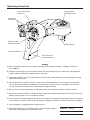
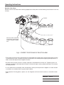
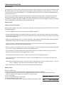
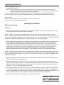
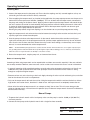
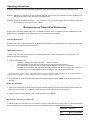
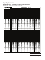
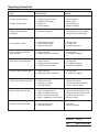
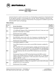
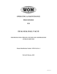
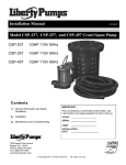
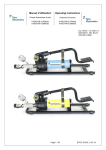
Operating Instructions and
Parts List for:
TWSD Series
SQUARE DRIVE HYDRAULIC WRENCH OPERATING MANUAL
Instructions Before Use
1. Read and understand all instructions before operating the hydraulic wrench. Most malfunctions in new equipment are the result of improper operation and/or setup. It is the operators responsibility to read, understand, and
follow all safety instructions.
2. Remove the hydraulic wrench from the shipping container and visually inspect all components for any shipping
damage. If any damage is found, notify the carrier immediately. DO NOT USE TOOL.
3. Locate a solid, secure reaction point to absorb and counteract the forces created as the hydraulic wrench is
operated.
4. Make sure the hydraulic hoses are free of the reaction point.
5. Momentarily pressurize the system. If the wrench tends to “ride up” or “creep”, stop and readjust the reaction
arm to a more solid and secure reaction point.
6. Cycle the hydraulic cylinder inside the wrench to ensure proper function.
Note: Each time the hydraulic cylinder inside the wrench is extended
and retracted, it is called a cycle.
Working Pressure
The maximum working pressure for this hydraulic wrench is 10,000 psi (68,900 kPa). Make sure all hydraulic
equipment used with this wrench are rated for 10,000 psi (68,900 kPa) operating pressure.
Hydraulic Connections
• Never connect or disconnect any hydraulic hoses or
fittings without first unloading the wrench and the
pump.
WARNING • Open all hydraulic controls several times to make
sure the system has been completely depressurized.
• If the system includes a gauge, double check the
gauge to make sure pressure has been released.• When making connections with quick disconnect
coupling, make sure the coupling are fully engaged. Threaded connections such as fittings, gauges, etc.,
must be securely tightened and leak-free.
Loose or improperly threaded fittings can be potentially dangerous if pressurized, however,
over-tightening can cause premature thread failure. Fittings should only be tightened until
they are secure and leak-free.
IMPORTANT
Sheet No.
1 of 12
Rev
Date: 16 July 2007
Operating Instructions
This is the safety alert symbol.
It is used to alert you to potential personal injury hazards. Obey all safety messages that follow this symbol to avoid possible injury or death
DANGER
Denotes an imminently hazardous situation which, if
not avoided, will result in death or serious injury.
WARNING
Denotes a potentially hazardous situation which, if not
avoided, could result in death or serious injury.
CAUTION
Denotes a potentially hazardous situation which, if not
avoided, may result in minor or moderate injury.
CAUTION
Caution used without the safety alert symbol indicates
a potentially hazardous situation which, if not avoided,
may result in property damage.
IMPORTANT
Denotes an operating or service procedure or condition considered essential for expedient and efficient
operation and service.
WARNING To help prevent personal injury,
• Always wear eye protection whenever operating
hydraulic equipment.
• Always wear hearing protection as required.
• Operation, repair, or maintenance of hydraulic
equipment should be performed by a qualified
person who understands the proper function of
hydraulic equipment per local directives and
standards.
• To prevent personal injury, use common sense. Do
not use any power equipment under the influence of
any mood altering substances.
• Never place your hands or other body parts near
a hydraulic fluid leak.
Never use your hands or other body parts to check
for a possible leak.
High pressure fluid can be injected under your skin
causing serious injury and/or infection.
• Electric motors may spark, causing an explosion
when flammable materials are present. Do not
operate in an explosive atmosphere or in the presence of conductive liquids. Use an air motor or
hand pump instead.
• To prevent electrical shock, make sure the
pump is properly grounded and the proper voltage
is being used.
• To prevent personal injury, the
WARNING remote control must only be used by
the wrench operator.
WARNING
Read and understand this material before
operating or servicing this equipment. Failure
to understand how to safely operate this tool
could result in a accident causing serious injury
or death.
•
Only qualified operators should install, operate,
adjust, maintain, clean, repair, or transport this
machinery.
•
Inspect tool before use. Replace any worn or
damaged parts. Failure to observe these warnings
can result in severe injury or death.
•
Keep work area clean and well lit.
•
When not in use, wrenches and accessories
should be properly stored to avoid deterioration.
• Do not use hydraulic hoses, pump power, or remote
control cords as means of moving the equipment.
• Make sure all hydraulic connections are securely
attached. Verify that the hydraulic hoses are not
kinked.
• Remain clear of the reaction arm during operation.
Never put body parts between the reaction arm and
the reaction point.
• Always use top quality impact sockets in good condition and remain clear of sockets during operation
because hidden flaws could cause breakage.
CAUTION
To prevent wrench damage,
always use the properly sized tool
and accessories. Do not use a
wrench for anything other than the
intended purpose.
Operating Instructions
MULTI AXIS SWIVEL
MANIFOLD
SQUARE DRIVE
RELEASE BUTTON
HYDRAULIC
COUPLINGS
REACTION ARM
RELEASE BUTTON
SQUARE DRIVE
REACTION ARM
REACTION ARM
PROTECTION PAD
Safety
A) Never exceed the torque wrench maximum working pressure (Advance 689 Bar / 10,000 psi, Retract 69
Bar / 1000 psi)
B) Keep hands and fingers clear of the torque wrench head and reaction arm area, before and during operation.
Fingers could be inadvertently trapped if care is not taken.
C) Keep other personnel clear of the working area and only allow trained personnel to use the equipment. Ideally
rope off the working area.
D) Prior to operation, ensure that all hoses, sockets and ancillary equipment is undamaged and fit for purpose.
Ensure that all torque wrench components (i.e. square drive, reaction arm, etc.) are properly attached and
secure. Ensure that the square drive retainer button is properly located.
E) Do not strike any of the components, including the socket, with a hammer in order to shock the nut free.
F) Check that reaction structures are strong and rigid enough to accept the torque tool reaction forces. Do not use
wedges, packing pieces, etc as a temporary reaction.
G) Take care when handling equipment. Quick connect couplings are especially susceptible to knocks and damage
and therefore care must be taken. Note that damaged couplings are difficult to connect. Do not force couplings.
H) Do not retighten any equipment whilst under pressure.
I) Some torque wrenches (and sockets) weigh in excess of 20Kg, therefore
ensure that lifting equipment is available and used.
Sheet No.
3 of 12
Rev
Date: 16 July 2007
Operating Instructions
J) Do not strike, misuse or abuse any of the equipment. If any abuse or misuse of the equipment is evident, the
warranty shall be invalid and the Manufacturer shall not be responsible for any injuries or failures as a result.
K) In some instances it may be necessary for the Operator to support the torque wrench whilst it is tightening, i.e.
upside down applications. If the torque tool cannot be strapped into position using ropes, etc, then the operator
must take the utmost care to avoid pinch points.
L) Never use the torque wrench with just one hose connected to the Advance port (port ‘A’). This will cause a pressure intensification within the retract chamber possibly leading to tool damage. Always ensure that both hoses
are connected.
OPERATION
CAUTION
For top performance, frequently inspect wrench, pump, and accessories for visual damage
Always follow instructions for proper wrench and pump maintenance.
Do not use other equipment to increase the capability (for example, hammering on socket wrench).
General
Each hydraulic wrench is supplied completely assembled and ready for use. A hydraulic pump is required to provide the speed and pressure that makes the hydraulic wrench system efficient and accurate.
Connecting the System
The hydraulic wrench head and power pack are connected by a 10,000 psi (68,900 kPa) single-line hose assembly.
Each end of the hose will have one female connector.
NOTE: DO NOT switch the hose connector from female to male. It is necessary for the hose to have a female connector to
engage the male connecter on the hydraulic wrench.
Electrical Connections
Make sure the power supply is compatible with the requirements of the electric pump motor. Minimize the length of
extension cords and be sure they are of adequate gauge and grounded.
Air Connections
Make sure the air flow rating is adequate and compatible prior to pressuring the pump. Make sure all connections
are tight and leak-free
Changing the Drive Direction
In order to change drive direction, press and hold the drive release button, then pull out the square drive. The
square drive, retainer cap and button assembly are now free from the torque wrench, take care not to lose them
To re-install, insert the square drive into the tool head (the square drive won’t enter until the splines are aligned)
and replace the retainer cap assembly.
As a check, pull the square drive to ensure that it is locked in position.
Using the Reaction Arm
The TWSD torque wrench features a 360° adjustable reaction arm. Although the reaction arm can be placed in a
multitude of positions, always try to use the torque tool with the reaction arm positioned parallel to the socket (i.e.
90° to the torque tool body). See Fig. 2 below
Sheet No.
4 of 12
Rev
Date: 16 July 2007
Operating Instructions
Reaction Point Safety
Extreme care must be taken when selecting appropriate reaction points and the following must be borne in mind at
all times.
SOCKET
REACTION ARM PARALLEL
TO SOCKET, A ND BUTTED
FIRMLY AGAINST FLANGE
NUT
Fig 2. CORRECT POSITIONING OF REACTION ARM
• The reaction structure must be rigid enough to accommodate the reaction forces from the torque wrench, which
can be extreme at times. Carefully assess the reaction points for suitability before applying the torque tool. If in
doubt, contact the torque wrench supplier for advice.
• Ensure that the reaction structure is suitably shaped to accommodate the reaction arm, Tapered surfaces are
generally unsuitable as the torque wrench tends to ‘ride up’ the taper, causing adverse tool loads. Flat surfaces
are most preferred.
• If in any doubt over the suitability of the reaction point, contact your torque wrench Supplier as various reaction
accessories are available which may prove more suitable.
• Don’t improvise. Packing pieces, spacers, etc. are dangerous and must never be used as a makeshift reaction
point.
Sheet No.
5 of 12
Rev
Date: 16 July 2007
Operating Instructions
Use of Sockets
Use high quality, industrial impact sockets at all times. Ensure that sockets are rated to accept the full torque output
of the torque wrench that they are to be used with. Regularly check the socket for cracks and flaws, if any sign of
damage is evident, discard it immediately as a damaged socket breaking under load could cause equipment damage or Operator injury.
Long reach or deep sockets are not recommended for use with hydraulic torque tools, as they tend to make the
wrench and socket unstable. However, some applications demand the use of long reach sockets, therefore it is
imperative that support is provided for both the socket and reaction facility. The same applies to socket accessories
such as extension bars, knuckle joints (not recommended), etc.
Setting Torque
Setting Up Prior to Operation
Setting up the equipment only takes a few minutes and some simple checks during set up will aid in the success of
the torquing operation.
• Obtain the torque value that is to be used for the tightening operation.
• Ensure that the bolt threads, nut threads and nut to flange contact faces are liberally coated with anti-seize lubricant of known friction co-efficient. Ensure that the lubricant friction co-efficient matches that which has been used
to derive the torque value.
• Make sure that the torque wrench is suitable to deliver the required torque. Should the torque value exceed 80%
of the torque wrench output, consider using a higher capacity torque wrench.
• Use the ‘Pressure – Torque Conversion Chart’ for the particular torque wrench to be used (supplied with the
torque wrench) to obtain the required pump pressure.
• Make sure that the socket to be used is of the correct type and size. A poor fitting or oversize socket will damage
nuts, induce inaccurate bolt loads and possible cause operator injury.
• Place the proper size impact socket on the square drive and secure it properly with the locking ring and pin.
Make sure the square drive is fully engaged into the socket.
• Place the wrench and socket on the nut. Make sure the socket is fully engaged on the nut.
• Make sure the reaction arm is placed firmly against a stationary object such as an adjacent nut, flange, equipment housing, etc.
NOTE: When positioning the wrench, make sure the hose connection will not hit any stationary object. This may
result in snapping a hose connection or breaking the coupler connection.
• Apply momentary pressure to the system to ensure proper wrench placement.
Setting Torque
Electric and Air Pumps
1. Make sure the system is fully connected and the proper power supply is available.
2. Use the Pressure/Torque conversion chart supplied with the wrench to find the required pressure setting.
NOTE: On electric or air pumps, this pressure is set on the pump.
3. Turn on the pump.
4. Press and hold the remote control button.
Sheet No. 6 of 12
5. Check the pressure on the gauge.
6. Increase or decrease pressure as required by loosening the locking ring on
Rev
Date: 16 July 2007
Operating Instructions
the pressure regulator valve and
turning the thumb screw.
NOTE: Turn the thumb screw clockwise to increase pressure and counterclockwise to decrease pressure.
When decreasing pressure, it is necessary to turn the thumb screw to a pressure setting below what is
desired and gradually increase pressure to the desired level.
7. Once the desired pressure is stabilized, release the remote control button and tighten the locking ring.
8. Prior to tightening a nut, press the remote control button and confirm the correct pressure has been set.
Manual Pumps
Find the required torque in the Pressure/Torque conversion chart and read
across the chart to the corresponding pressure.
Operating the Wrench
Electric or Air Pump
Tightening
1. Connect the torque wrench to the pump unit. Ensure that the couplings are fully screwed together as they are
self-sealing and will restrict oil flow if not fully connected.
NOTE : TWSD torque wrenches are equipped with a pressure release valve built into the Multi-Axis Swivel
Manifold to protect against retract pressure intensification should the retract port hydraulic coupling not be fully connected, or become loose during use. If an intensification occurs, the valve will bleed hydraulic oil externally from the
manifold yoke. Note that oil bleeding from the swivel manifold is not a sign of seal leakage.
2. Prior to applying the torque wrench (and socket) to the application, the pump output pressure must be pre-set to
relieve at the pressure obtained from the ‘Pressure – Torque Conversion Chart’. This can be done with the
torque wrench connected to the pump and resting on the floor or bench. Applying advance pressure to the
torque wrench will extend the piston until it reaches the end of its stroke whereby the pump pressure will build.
Holding the wrench at the end of its stroke will allow the pump pressure to be adjusted. Retract the torque
wrench piston and advance again making sure that the pump relieves at the desired pressure setting.
Blanking the pump outlets using blank couplings can also be done to carry out the pump pressure setting.
NOTE : Allow time for the wrench to retract. If another advance stroke is made before the torque wrench has fully
retracted, the ratchet mechanism may not engage correctly, causing it to jump a ratchet tooth (probably damaging
the ratchet). Before applying another advance stroke, make sure that the pump is idling at 69 Bar (1000psi), which
indicates full retraction.
3. Apply the torque wrench and socket to the nut to be tightened, ensuring that the reaction arm butts firmly and
squarely against the selected reaction point.
4. Start the pump and advance the torque wrench. As the wrench strokes forward the reaction arm will press
against the reaction point and the nut / socket will rotate. When the torque wrench reaches the end of its stroke,
the pump pressure will build rapidly. Retract the torque wrench (the wrench ratchet mechanism will be heard
clicking as it retracts), and apply another forward stroke
5. Several forward strokes are made until the nut ceases to rotate during the stroke, (known as stalling), but bear
in mind that nut rotation will always cease at the end of the wrench stroke and must not be confused with the
wrench stalling. WHEN THE WRENCH STALLS, APPLY ANOTHER FORWARD STROKE AND OBSERVE THE
PUMP PRESSURE GAUGE, WHICH SHOULD READ THE DESIRED PRE-SET PRESSURE.
6. Retract the torque wrench, stop the pump unit, and remove from the nut
Sheet No.
7 of 12
Rev
Date: 16 July 2007
Operating Instructions
Loosening Bolts
1. Connect the torque wrench to the pump unit. Ensure that the couplings are fully screwed together as they are
self-sealing and will restrict oil flow if not fully connected.
2. Prior to applying the torque wrench (and socket) to the application, the pump output pressure must be pre-set to
deliver the maximum pressure of 690 Bar (10,000psi). This can be done with the torque wrench connected to
the pump and resting on the floor or bench. Applying advance pressure to the torque wrench will extend the piston until it reaches the end of its stroke whereby the pump pressure will build. Holding the wrench at the end of
its stroke will allow the pump pressure to be adjusted. Retract the torque wrench piston and advance again
making sure that the pump delivers full pressure.
Blanking the pump outlets using blank couplings can also be done to carry out the pump pressure setting.
3. Apply the torque wrench and socket to the nut to be loosened, ensuring that the reaction arm butts firmly and
squarely against the selected reaction point.
4. Start the pump and advance the torque wrench. As the wrench strokes forward the reaction arm will press
against the reaction point. As the pump pressure builds (and thus torque applied to the nut), the nut will break
free. Once the nut has been released, remove the nut by hand if loose enough, or alternatively use an impact
wrench, it is not recommended to use the torque wrench.
NOTE : Should maximum pump pressure be reached, and the nut has still not broken free, use a higher capacity torque
tool (providing that the nut/bolt material will accept the higher torques without damage). Do not, under any circumstances,
strike the socket or torque wrench in an attempt to ‘shock’ the nut free.
5. Retract the torque wrench, stop the pump unit, and remove from the nut.
Notes on Loosening Bolts
Loosening of bolts using torque tools can be unpredictable and often unsuccessful, especially if the nuts and bolts
are severely corroded. However, some measures can be carried out to increase the success rate of nut breakout.
• In general, loosening mildly rusted bolts requires up to twice the make up torque to release the nut. Heavily corroded bolts may take up to three times the make up torque. Ensure that the bolt and nut material is strong
enough to accept these higher torques.
• Remove surface rust and scale using a wire brush. Apply releasing oil to the nut, bolt and bearing face, and allow
time for the release oil to soak in and penetrate.
• Only use the torque wrench to break the nut free. Using the torque tool to wind the nut from the bolt can induce
high torsion and reaction forces, therefore it is better to use and impact wrench to completely remove the nut.
• Never strike the socket or torque wrench in an attempt to ‘shock’ the nut free. This will cause damage to the
socket and torque wrench, and could result in operator injury. Evidence of torque wrench abuse will invalidate the
Manufacturer’s Warranty.
Manual Pumps
1. To operate the hydraulic wrench with a hand pump, make sure the pump is rated at 10,000 psi (68,900 kPa)
maximum pressure.
2. Connect the hand pump to the hydraulic wrench with a single-line hose assembly.
Sheet No.
8 of 12
Rev
Date: 16 July 2007
Operating Instructions
Tightening
1.
2.
3.
4.
Determine the required pressure.
Make sure the hydraulic wrench and the reaction arm are in the tightening mode.
Pump the hand pump to advance the hydraulic cylinder inside the wrench until the socket stops turning.
Release the pump pressure. The hydraulic cylinder inside the wrench will automatically retract and an audible
“click” will be heard. This completes one cycle.
Loosening
1. Make sure the hydraulic wrench and the reaction arm are on the loosening mode.
2. Pump the hand pump to advance the hydraulic cylinder inside the wrench. As pressure builds, the bolt will begin
to loosen.
3. Stop pumping when the socket stops turning.
4. Release the pump pressure. The hydraulic cylinder inside the wrench will automatically retract and an audible
“click” will be heard. This completes one cycle.
5. Continue to loosen the nut with successive cycles until the nut can be removed by hand.
6. Proceed to the next nut.
7. General Torquing Procedure
General Torquing Procedure
The following procedure is for use with TWSD torque wrenches and outlines the basic steps in order to carry out
the torque tightening of a flanged joint. It is important that personal protective clothing (gloves, footwear, safety helmet, eye protection) is worn at all times not only by the Operator, but also by any personnel within the work area.
The torquing procedure is compiled around using a single torque wrench, the object of the procedure being to
accurately achieve a pre-determined residual bolt stress.
SAFETY: Prior to commencement of bolt torquing ensure that:
• All necessary safety precautions have been carried out
• Personnel involved in torquing are competent and fully trained in the use of hydraulic torque tools and tightening
techniques.
• The procedure and data to be used is authorized by a responsible Engineer.
• The joints / pipework to be worked on are not ‘live’. Joints must be at zero pressure and free from hazardous
substances.
• Torque value selected must be based upon the lubricant applied.
STAGE 1 Number each bolt consecutively, 1, 2, 3 etc
STAGE 2 Using torque wrenches (if necessary), square up the flanged joint.
STAGE 3 Working in a diametrical sequence (tightening opposite bolts) apply the minimum torque available. i.e.
set pump to lowest possible output (1000psi). Note the sequence used.
STAGE 4 Repeating the above noted tightening sequence, apply approximately 25% of the torque value specified
in the torque data.
STAGE 5 Using the same noted tightening sequence, apply approximately 50% Sheet No.
of the torque value specified in the torque data.
Rev
9 of 12
Date: 16 July 2007
Operating Instructions
STAGE 6 Using the same noted tightening sequence, apply the full torque value specified in the torque data.
STAGE 7 Working in a clockwise (or anti-clockwise) direction, make a final pass around the flange, tightening each
bolt to the full torque value specified in the torque data.
STAGE 8 Following completion of Stage 7, using a hammer, “ring” each nut to ensure that each bolt has been correctly loaded and that no slack bolts remain.
Maintenance and Preventative Maintenance
Inspect hoses and fittings before every use. Connections must be clean and properly connected before each use.
Replace worn or damaged fittings. Keep tools clean and protected from damage.
Post-Use Maintenance
In order to keep the TWSD torque wrench in good working condition, it is recommended that simple post-use maintenance be carried following each period of use.
TWSD Torque wrench
1. Wipe away any debris that may have accumulated, particularly around the square drive area, reaction arm
splines and hydraulic couplings.
2. Check the following areas :
Hydraulic Couplings for signs of damage - replace if evident.
Swivel Manifold. Ensure the spiral retaining ring is present and fitted correctly.
Ensure the Guard is present and securely attached. Replace / re-attach as necessary.
Remove the square drive from the torque wrench and inspect for damage, cracks, etc. Re-lubricate
the bearing journals using ‘Lithium Complex EP Grease’ and replace the square drive.
Note that that the torque tool drive components must be lubricated using the specified product only. Using alternative lubricants will affect the torque tool output and possibly lead to premature component failures.
3. It is preferable to lightly spray the torque wrench with water repellent spray (WD40), prior to placing back into
storage.
Hoses and Ancillaries
1. Clean and inspect each hydraulic hose and quick connect coupling. Check the entire length of the hose for cuts,
abrasions and damage. Any evidence of hose damage and the entire hose must be replaced.
2. Coat each quick connect coupling with a water repellent spray (WD40).
Maintenance, Servicing and Warranty
In addition to post-use maintenance, and to ensure that the Product Warranty remains valid, it is recommended that
routine maintenance and servicing be carried out by the Manufacturer or authorized Service Centre.
Sheet No.
10 of 12
Rev
Date: 16 July 2007
Operating Instructions
TWSD SERIES HYDRAULIC TORQUE WRENCH
PRESSURE - TORQUE CONVERSION CHART
Sheet No.
11 of 12
Rev
Date: 16 July 2007
Operating Instructions
Fault
Cylinder will not advance.
Cylinder will not retract.
Torque wrench operates
backwards
Possible Cause
1.
2.
3.
4.
Coupling not fully mated
Cylinder seal leakage
Pump unit
Faulty coupling
Remedy
1.
2.
3.
4.
Check coupling
Replace seal
Check pump unit
Replace coupling
1. Reversed couplings.
1. Check pump, hose and torque
wrench for cross connection
Pressure will not build
1. Cylinder Seal leakage
2. Swivel Seal leakage
3. Defective pump unit
1. Change seals
2. Change seals
3. Check pump unitPa
Pressure builds, but wrench
does not move
1. Hose restriction
2. Coupling not fully assembled
1. Change hose
2. Fully tighten coupling
Slow torque wrench operation
1. Hose restriction
2. Coupling not fully assembled
3. Pump flow rate too small
1. Change hose
2. Fully tighten coupling
3. Use higher flow pump
Erratic or slow retraction speed
1. Hose restriction
2. Coupling not fully assembled
1. Change hose
2. Fully tighten coupling
Torque wrench does not ratchet
1. Broken drive shoe
2. Jammed drive shoe
3. Damaged ratchet
1. Replace drive shoe
2. Check drive shoe and spring
3. Check / replace ratchet
Ratchet jumps whilst driving
1.
2.
3.
4.
1.
2.
3.
4.
Difficulty in hose connection
1. Pressure within hose
2. Damaged coupling
Worn / damaged ratchet
Worn / damaged drive shoe
Wrench incorrectly retracted
Weak / snapped drive shoe spring.
Replace ratchet and drive shoe
Replace ratchet and drive shoe
Allow time to fully retract.
Replace springs
1. Vent hose
2. Replace coupling
Sheet No.
12 of 12
Rev
Date: 16 July 2007