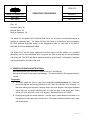
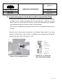
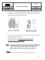
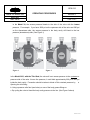
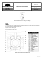
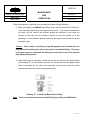
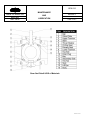
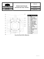
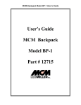
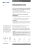
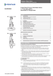
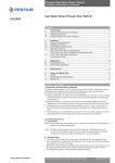
1
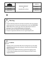
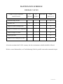
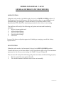
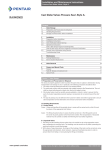
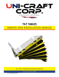
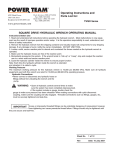
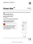
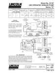
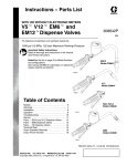
WOM
OPERATING & MAINTENANCE
PROCEDURES
FOR
DUAL-SEAL BALL VALVE
FOR PRODUCTION, PIPELINE, TOP-SIDE AND UNDERGROUND
STORAGE SERVICES
Manual Identification Number: OPM-316, Rev. 4
Revised February, 2010
A429EN1.08 Rev.4
TABLE OF CONTENTS
DESCRIPTION
SECTION
Operating Procedures for a Model 30 and
Model 30-D Dual Seal Ball Valve................................................................ I
Maintenance & Lubrication for Model 30
and Model 30-D Dual Seal Ball Valve......................................................II
Trouble Shooting & Routine Functional Testing
for Model 30 and Model 30-D Dual Seal Ball Valve ............................ III
Valve Storage .............................................................................................. IV
EHSR Requirement of Warning & Caution ............................................ V
Appendices
Maintenance Schedule............................................................................ A
Assembly Drawings.................................................................................B
Bill of Materials........................................................................................ C
API Specification 6D Testing Procedures............................................ D
General Design Standard ........................................................................E
A429EN1.08 Rev.4
SECTION I
A429EN1.08 Rev.4
OPM-316
WOM
MODEL 30 / MODEL 30-D
OPERATING PROCEDURES
REVISION: 4
DUAL SEAL
SECTION: I
BALL VALVE
PAGE: 1 OF 5
Size: All
Pressure Class: All
Material Class: All
Mode of Operation: All
The Model 30 and Model 30-D Dual-Seal Ball Valve use a trunnion mounted ball design to
achieve an upstream seal. The Model 30 Dual-Seal valve is bi-directional, and incorporates
W.O.M.’s patented Dual-Seal design of two independent seals on each side of the ball for
extended valve life and additional safety.
The Model 30-D use the same upstream Dual-Seal design, but the addition of a modified
secondary seal on the downstream side now gives the valve a third seal on the downstream
side of the ball. The 30-D also has a “preferred direction of flow arrow” indicated by a stainless
steel tag mounted on the side of the body.
A. GENERAL OPERATING INSTRUCTIONS:
Ball valves should never be used to "throttle" line fluid. Throttling any
ball valve will result in seat and/or ball damage. This valve should be fully opened and fully
closed.
To Operate:
1. To OPEN, rotate the lever or gear box handwheel counter-clockwise the valve has
moved 90 degrees and strong resistance is felt. There is a shoulder, the “end-stop,” on
the valve which gives the valve a positive stop in the open position. Worm gear operated
valves will have a position indication cast on to the top plate of the worm gear. These
valves will travel only turn ¼ turn or 90 degrees. Reverse direction to CLOSE.
2. Power-opening with an electric actuator – use the open / closed stops on the valve or on
the gear box to fully open and close the valve. The electric actuator should be set to stop
with torque limits.
A429EN1.08 Rev.4
OPM-316
WOM
MODEL 30 / MODEL 30-D
OPERATING PROCEDURES
REVISION: 4
DUAL SEAL
SECTION: I
BALL VALVE
PAGE: 2 OF 5
B. Operation Instructions for Double Block and Bleed using the Bleed Fitting:
The W.O.M. Dual-Seal Ball Valve is a Double Block and Bleed valve (DBB) Double Block
and Bleed can be verified by following API 6D test procedures.
With the line under
pressure, the valve center body cavity can be vented to the atmosphere and completely
de-pressurized with the ball in either the open or closed positions.
After venting, if no additional line pressure enters the valve, the seals have been proven to
be intact.
Bleed the body cavity pressure through the vent (bleeder) fitting located in the upper
quadrant of the ball valve’s center section. This fitting has two venting ports 180 degrees
opposite each other. Refer to Drawings “A” & “B”.
Figure 4 (4” & Larger Ball Valves)
Drawing “B” - 4” valve & Up
Body Vent (Bleeder) Fitting
A429EN1.08 Rev.4
OPM-316
WOM
MODEL 30 / MODEL 30-D
OPERATING PROCEDURES
REVISION: 4
DUAL SEAL
SECTION: I
BALL VALVE
PAGE: 3 OF 5
1. 4” and larger valves: To open the vent ports use a wrench on the upper (smaller) hex
head stem of the fitting and turn the wrench counter-clockwise*. This will allow any
trapped pressure in the body to vent to atmosphere.
Figure 3 (2” & 3” Ball Valves)
Drawing “A” - 2” & 3” valve
Body Vent (Bleeder) Fitting
2. 2” and 3” valves: same procedure as for 4” and larger, but the vent fitting uses an allen
head wrench to open and close the ports.
3. Close the vent fitting by turning the small hex head stem, (or allen head)
clockwise until it snugs tight. This fitting must be in the closed position
at all times other than for block and bleed tests.
* Caution :
When turning the smaller hex head, make sure the threaded body of the
fitting does not unthread out of the ball valve center section. You may need
to put a back-up wrench on the larger hex head. (See Figures 3 & 4)
** ALWAYS USE EYE PROTECTION DURING THIS PROCEDURE
C. VENTING:
No WOM ball valve can trap pressure in the body. All valves are self-relieving.
A429EN1.08 Rev.4
OPM-316
WOM
MODEL 30 / MODEL 30-D
OPERATING PROCEDURES
REVISION: 4
DUAL SEAL
SECTION: I
BALL VALVE
PAGE: 4 OF 5
In the Model 30, the excess pressure bleeds to the side of the valve with the lowest
pressure. For example: if you have 1000 psi on the upstream side of the valve and 500 psi
on the downstream side, the excess pressure in the body cavity will bleed to the low
pressure (downstream) side. (See Figure 1)
Figure 1
Figure 2
In the Model 30-D, with the Third Seal, the valve will vent excess pressure to the upstream or
pressure side of the valve. At zero line pressure, it could hold approximately 200 psi to 300 psi
inside the body cavity. Precaution should be taken to bleed off this retained pressure by,
a.
Opening the vent fitting,
b. Using a pressure relief tool (see below) on one of the body grease fittings or
c. By cycling the valve to bleed the body cavity pressure to the line. (See Figure 2 above)
A429EN1.08 Rev.4
OPM-316
WOM
OPERATING PROCEDURES
MODEL 30 / MODEL 30-D
REVISION: 4
DUAL SEAL
SECTION: I
BALL VALVE
PAGE: 5 OF 5
Pressure Relief Tool for use with grease fittings
NOTES:
1. Always follow your Company’s specified operating instructions for the media being produced.
2. Assembly drawing of Model 30 Ball Valve
3. Details of stem sealing area
4. Bill of Material for Ball Valve.
Stem Seal Details & Bill of Materials
A429EN1.08 Rev.4
SECTION II
A429EN1.08 Rev.4
OPM-316
WOM
MAINTENANCE
MODEL 30 / MODEL 30-D
AND
DUAL SEAL
LUBRICATION
REVISION: 4
SECTION: II
BALL VALVE
PAGE: 1 OF 5
Size: All
Pressure Class: All
Material Class: All
Mode of Operation: All
A. GENERAL INSTRUCTIONS :
1. Preventive Maintenance is based on Operating Conditions and the Company’s own
Preventative Maintenance Program.
2. The stem seals are lubricated at the factory.
No maintenance needed for normal
operation.
3. Model 30 and Model 30-D uses two sets of dry permanently lubricated bearings, the
upper trunnion and one on the lower trunnion. These bearings do not require lubrication
under normal operating procedures.
4. Worm gear - The worm gear operator needs annual additions of heavy non-pourable
grease to lubricate the worm gear shaft. Grease can be injected thru the grease zert
located on the gear housing, or you can unbolt the gear box and pry off the cover plate.
Add grease until the area is nearly full. Grease will help keep water from accumulating
in the gear box. NOTE: In freezing weather, any water in the gear box can freeze and
damage the box.
B. SEAT LUBRICATION :
It is not necessary to lubricate the seats during normal operations of this valve. The
seats are designed for the resilient seals to float against the ball without requiring
grease.
Caution : There will be some trapped pressure in the body cavity (from the last
open/close cycling) If the valve is handling H2S or similar toxic materials,
appropriate safety precautions and protective equipment should be used.
Consult your safety coordinator if unsure.
A429EN1.08 Rev.4
OPM-316
WOM
MAINTENANCE
MODEL 30 / MODEL 30-D
AND
DUAL SEAL
LUBRICATION
BALL VALVE
REVISION: 4
SECTION: II
PAGE: 2 OF 5
Follow this sequence: (preferred, but not essential to bleed off body pressure)
1. Body vent fitting is the MIDDLE body fitting. Note: Use the instructions in Section C
of the Operating Instructions to de-pressurize the valve. If you cannot de-pressurize
the valve, you will need to use sufficient grease gun pressure to over come the
pressure in the valve, plus the pressure required to move the grease out of the
grease gun. In cold weather, grease will thicken and require more pressure to pump
through the gun.
Caution : Never remove any fitting or plug that appears to be threaded into the
body without first making sure there is no pressure beneath the fitting. There may
be trapped pressure underneath the fitting that could eject it out of the threads
with deadly consequences.
2. When body cavity is completely vented, remove the vent cap from the grease fitting
(See drawing “E”) on the pressure side seat. Do not remove the entire grease fitting
which is threaded into the valve end connection. (A ball check inside the fitting
prevents pressure loss, but will accept grease input).
Drawing “E” - Vented Cap Body Grease Fitting
Note : There is no buried check valve beneath ANY grease fitting of a WOM Valve.
A429EN1.08 Rev.4
OPM-316
WOM
MAINTENANCE
MODEL 30 / MODEL 30-D
AND
DUAL SEAL
LUBRICATION
BALL VALVE
REVISION: 4
SECTION: II
PAGE: 3 OF 5
3. Connect a high pressure (10,000psi) grease gun to seat grease fitting on the
pressure side of the valve.
4. Pump lubricant into the valve seat. The grease will travel around the entire “annulus”
between the Primary and Secondary Seals, filling the area up between the O.D.
elastomers. This will lubricate the seals and allow them to float, as designed, if you
have determined that they are not sealing against the ball.
5. Never exceed the working pressure of the valve when pumping grease into the
seats. Refer to Appendix E, Table 2.1 from API 6D.
6. Remove grease gun
7. Replace vent cap on grease fitting and lightly tighten.
C. Draining the valve to remove moisture:
Depending on climate and your Company’s standard operating
procedures, you may need to periodically drain accumulated water and contaminants
from the center body cavity of the valve. Choose the lowest body fitting to the ground,
depending on the orientation of the valve. It will either be the center or middle body vent
fitting, or the lower trunnion fitting. The lower trunnion fitting is typically a solid drain
plug. (See Drawing C)
Drawing “C”
Solid Cavity Drain Plug - all valve sizes
A429EN1.08 Rev.4
OPM-316
WOM
MAINTENANCE
MODEL 30 / MODEL 30-D
AND
DUAL SEAL
LUBRICATION
BALL VALVE
REVISION: 4
SECTION: II
PAGE: 4 OF 5
As an option, this plug can be replaced with a quarter turn drain valve. Removing solid
drain plug allows water and sediment to drain from valve. Be sure this plug or a valve is
re-installed prior to commissioning valve.
Do not remove this plug without first venting valve body cavity to the atmosphere.
D. Storage
a. Place the valve in the full open position
b. Inject grease in to each seat grease fitting until you see excess grease oozing out
from between the ball and seat on the inside of the valve cavity (see instruction B
under Seat Lubrication.)
c. Coat the end connection seal surfaces with grease to prevent rust.
d. Use flange covers to keep out debris.
e. The valve should remain in the open position until installed.
NOTES :
1. Always follow your Company’s specified operating instructions for the media being
produced.
2. Assembly drawing of Model 30 Ball Valve
3. Details of stem sealing area
4. Bill of Material for Ball Valve
5. Stem Packing Tag Drawing
Stem Packing Tag
A429EN1.08 Rev.4
WOM
OPM-316
MAINTENANCE
MODEL 30 / MODEL 30-D
AND
DUAL SEAL
LUBRICATION
BALL VALVE
REVISION: 4
SECTION: II
PAGE: 5 OF 5
Stem Seal Detail & Bill of Materials
A429EN1.08 Rev.4
SECTION III
A429EN1.08 Rev.4
WOM
MODEL 30 / MODEL 30-D
OPM-316
TROUBLE SHOOTING AND
ROUTINE PUNCTIONAL TESTING
REVISION: 4
DUAL SEAL
SECTION: III
BALL VALVE
PAGE: 1 OF 4
Size: All
Pressure Class: All
Material Class: All
Mode of Operation: All
A. Stem Packing Troubleshooting:
1. If you see slight weepage of valve contents coming from around the stem this is an
indication of a slight stem packing leak. This may be corrected by injecting sealant into
the stem packing fitting. Use the same procedures as adding grease in the seat grease
fitting, instruction “B Maintenance instructions for injecting lube/sealant” into this area.
(See Figure 5) Keep in mind that the area to inject grease in to is very small and a
single stroke from a high pressure grease gun should inject enough grease to affect a
seal. If the valve can be cycled, open and close it several times to help distribute the
grease around the O.D. of the stem.
A429EN1.08 Rev.4
WOM
MODEL 30 / MODEL 30-D
OPM-316
TROUBLE SHOOTING AND
ROUTINE PUNCTIONAL TESTING
REVISION: 4
DUAL SEAL
SECTION: III
BALL VALVE
PAGE: 2 OF 4
Figure 5
A429EN1.08 Rev.4
OPM-316
WOM
TROUBLE SHOOTING AND
MODEL 30 / MODEL 30-D
ROUTINE PUNCTIONAL TESTING
REVISION: 4
DUAL SEAL
SECTION: III
BALL VALVE
PAGE: 3 OF 4
2. If you see a steady flow of valve contents coming from around the stem this may
indicate significant damage to the stem seals. Use the same instructions above but Inject
enough sealant into the stem packing fitting to reduce the amount of the leak until an
authorized service representative can be consulted.
B. Shell Testing
The valve is to be shell tested in the PARTIAL OPEN position. The test is to be done as per API
6D, latest edition.
The shell test is to verify if the following seal points are intact and functioning properly:
1.
Body to Upper/Lower Trunnion gasket seals
2.
All Body Bleed Fittings
3.
Stem Seals
If any of the above seal points appear to leak or are weeping, consult the WOM factory
representative. (See Stem Seal Trouble Shooting at the beginning of this section.)
C. Seat Testing
The valve must be in the FULLY CLOSED position.
The Seat Test is done in accordance with API 6D, latest edition.
The Seat Test will verify if the following seal points are intact and functioning properly:
1.
The face seal of the seat against the ball.
2.
The seat to body seal where the outside diameter elastomer seals between the
body and the seat assembly
NOTES :
1. Always follow your Company’s specified operating instructions for the media being
produced.
2. Assembly drawing of Model 30 Ball Valve
3. Details of stem sealing area
4. Bill of Material for Ball Valve.
A429EN1.08 Rev.4
WOM
MODEL 30 / MODEL 30-D
OPM-316
TROUBLE SHOOTING AND
ROUTINE PUNCTIONAL TESTING
REVISION: 4
DUAL SEAL
SECTION: III
BALL VALVE
PAGE: 4 OF 4
Stem Seal Detail & Bill of Materials
A429EN1.08 Rev.4
SECTION IV
A429EN1.08 Rev.4
OPM-316
WOM
MODEL 30 / MODEL 30-D
VALVE STORAGE
REVISION: 4
DUAL SEAL
SECTION: IV
BALL VALVE
PAGE: 1 of 2
CAUTION: For handling and or lifting, the lifting equipment (fasteners, hooks,
etc.) must be sized & selected white talking into account the valve weight
indicated in the packing list. Do not use the lifting points located on the
actuator , if any, to lift the valve. Caution must be taken during the handling to
avoid that this equipment passes over the workers or over any other place
where a possible fall could cause damage. Every employee should aware about
the safety regulations during handling of the valve.
1.1 Preparation and Preservation for Shipment
All valves are properly packed in order to protect the parts that are subjected to
deterioration during transportation and storage on site. In particular precautions
should be followed as below:
a) The valves must be packed with the ball in the open position.
b) The valve ends surface shall be protected with suitable protective. The ends shall
be closed with plastic/ rubber disc.
c) All actuated valves must be carefully securely palleted or crated in order to
ensure that the parts of actuator don’t extent beyond the crate.
d) The type of packing must be defined in the Customer’s order & shall be
appropriate to ensure safe transportation to final destination & eventual
conservation before installation.
1.2 Handling Requirements
A- Packed Valves
Crates: Lifting & Handling of the packed valves in crates will be carried out by a
fork lift by means of appropriate lifting slings.
Cases: The Lifting of packed valves in cases should be carried out in the lifting
points and at the center of gravity position, which have been marked. The
transportation of all packed material must be carried out safely with safety
measures.
A429EN1.08 Rev.4
OPM-316
WOM
MODEL 30 / MODEL 30-D
VALVE STORAGE
REVISION: 4
DUAL SEAL
SECTION: IV
BALL VALVE
PAGE: 2 of 2
B- Unpacked Valves
1. The lifting & the handling of these valves must be carried out on pallets,
protecting the machined surface to avoid any damage.
2. For big sizes valves, the sling & hook must be carried out by using the
appropriate tools (brackets, hooks, fasteners, ropes) and load balancing
tools in order to prevent them from falling during the lifting & handling.
1.3 Storage and Preservation before Installation
In case the valves have to be stored before installation, the storage has to be carried
out in a controlled way, and has to perform in accordance with following way:
1. The valves have to be stocked in a closed, clean and dry area.
2. The ball must be in the open position and the faces must be protected with
plastic or rubber discs with straps.
3. Periodical checks have to be carried out in the storage area to verify that the
above mentioned conditions are maintained.
For actuated valves, in addition to the above, refer the warnings in the actuator
manufacturer manual.
! Note:
Storage in the open area for limited period can be considered only in case the
valves have appropriate packing.
Do not place consignment packages directly on the ground.
Do not expose consignment packages to the weather or directly to the sun
Check the packaging every two months.
A429EN1.08 Rev.4
SECTION V
A429EN1.08 Rev.4
OPM-316
WOM
MODEL 30 / MODEL 30-D
DUAL SEAL
BALL VALVE
EHSR REQUIREMENT
OF
WARNING & CAUTION
REVISION: 4
SECTION: V
PAGE: 1 of 2
IN
A
T
S
L
O
!
Warning
1. Verify the direction of the flow in the line corresponds to the arrow indicated
on the valve body. If valve has a flow direction arrow, this is the PREFERRED
DIRECTION of flow, but the valve will seal in either direction and is bidirectional. Every valve that WOM makes is bi-directional.
2. Refer the actuator user manual for the actuator-operated valve.
3. Verify the overpressure relief device in case of gas & liquid service.
!
Caution
If piping system is pressurized with water for testing and in case the piping
system has been shut down after testing for a long time, the following steps
should be followed:
1. Use the corrosion inhibitor with water to pressurize the piping system.
2. After testing, the piping system should be depressurized and test water
completely drained.
A429EN1.08 Rev.4
OPM-316
WOM
MODEL 30 / MODEL 30-D
DUAL SEAL
BALL VALVE
EHSR REQUIREMENT
OF
WARNING & CAUTION
REVISION: 4
SECTION: V
PAGE: 2 of 2
S
A
E
L
R
P
C
M
N
T
!
Warning
Depressurize the line before starting any seals replacement of the valve or
maintenance of the valve. Failure to do so may cause serious personal injury
and damage to the valve.
V
alv
R
e
m
o
If the valve needs to be removed from the line for some reason, the user should
ensure the following:
1. The valve is depressurized.
2. the pipe shall be cut as far away from the valve as possible.
!
Warning
Depressurize the line before starting any maintenance. Failure to do so may
cause serious personal injury and damage to the valve.
A429EN1.08 Rev.4
APPENDIX A
A429EN1.08 Rev.4
MAINTENANCE SCHEDULE
FOR BALL VALVES
LUBRICATION & GENERAL
AS
BI-
MAINTENANCE
NEEDED
WEEKLY
1. Lubricate Body & Seats
2. Pressure Test
MONTHLY
SEMIANNUALLY
X
X
3. Inspect for Stem Packing Leaks
X
4. Inspect for Smooth Valve Operation
X
5. Inspect Flanges for Leaks
X
6. Inspect gear box
X
7. Inspect Grease Fitting & Inj. Ports
X
A. In order to maintain the W.O.M. warranty, the above maintenance schedule should be followed.
B. In the event of abnormalities, see Troubleshooting Guide for possible cause and recommended repair.
A429EN1.08 Rev.4
APPENDIX B
A429EN1.08 Rev.4
APPENDIX C
A429EN1.08 Rev.4
APPENDIX D
A429EN1.08 Rev.4
MODEL 30/30-D BALL VALVE
GENERAL HYDROSTATIC PROCEDURES
SHELL TESTING:
When the valve needs to be Shell tested, it has to be in PARTIAL OPEN position. If
Shell testing is done in full open or full closed position, there is a possibility the seal
assemblies may get damaged. Consult the factory or the latest edition of API
Specification 6D for Shell Test maximum pressures for the valve you are testing.
The shell test will verify if the following seal points are intact and functioning
property:
1.
Body to bonnet gasket seal
2.
All body bleed fittings
3.
All seat sealant fittings
4.
Stem injection fittings
5.
Stem seals
In any of the above seal points appear to be leaking or weeping, consult the factory
representative.
SEAT TESTING:
When the valve needs to be Seat tested, it has to be in FULLY CLOSED position.
Consult the factory or the latest edition of API Specification 6D for Seat Test maximum
pressures for the valve you are testing. See Table 5.1 from API Spec 6D
The seat test will verify if the following seal points are intact and functioning property:
1.
The face seal of the seat against the ball
2.
The outside diameter elastomer seal on the seat assembly
A429EN1.08 Rev.4
APPENDIX E
A429EN1.08 Rev.4
ATTACH
DUAL-SEAL
BALL VALVE
BROCHURE
A429EN1.08 Rev.4