1
PRO~B MOBILE DENTAL UNIT OPERATING INSTRUCTIONS
COMPRESSED AIR SUPPLY
This is normally supplied from the compressor mounted on the base of the Unit but may be
separate and remotely located. (See separate Operating Instructions for the compressor). Before
attempting to operate the Dental Unit ensure that the compressor is switched on, reservoir is full (the
motor will have cut out) and normal line pressure of 65psi has been attained.
OPERATING INSTRUCTIONS
INTRODUCTION
The PRO-B Dental Handpiece Control Unit is designed to deliver air and water supplies to the dental
handpieces and a syringe spray.
The PRO-B has two handpiece tubings which are selected manually by use of the Handpiece selection
switch. This automatically routes air and water supplies to the selected Handpiece. The flow rates are
pre set by the operator to match the handpiece and operators needs. The movement is controlled by the
operator using the Foot Control.
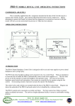
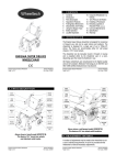
The control valves and switches are mounted under the base of the PRO-B control head. Left hand side
of the Diagram shows the underside of the tabletop and each control valve is identified by a reference
letter.
The PRO-B control unit is mounted on a mobile frame and the castors have brakes to protect against
accidental movement. The Unit has a height adjustment facility to ensure a comfortable working
position also enables storage beneath work counters etc.
Roots Vet Dental Supplies Ltd
Reg Office: Sparkenhoe House, Southfield Road LE10 1UB Company Reg (England) 6570426
www.rootsvetdental.co.uk
email:
[email protected]
/2
WARNING – Please read this manual prior to using or making any adjustments to connected handpieces.
WARNING – Never exceed the handpiece manufacturer’s recommended pressures.
WARNING – Never run a handpiece without a bur/drill bit or manufacturer’s blank fitted.
A – MASTER ON/OFF SWITCH
The PRO-B is unable to operate without activation of this switch.
action and the toggle is grey.
The switch has a positive ON/OFF
Put the toggle to the ‘ON’ position and the air and water supply will be opened, allowing air and water to
flow into the PRO-B pneumatic circuits.
B – SYRINGE SPRAY
The syringe is always located in the left holder on the holder bar. The syringe has two button valves,
which when pressed release air or water. The left button supplies water and has a droplet legend. The
right button has a cloud legend and supplies compressed air. The two buttons may be pressed together
to provide a fine mist spray. The harder either button is pressed the more air or water will be released.
The syringe is supplied with a removable tip and the base of the tip is a locking chuck assembly that
securely retains the tip. Tip can be removed for sterilization for autoclaving/cold solutions.
To remove the tip, press and hold the outer ring at the base of the tip and gently remove the tip then
release the ring.
To replace the tip, press and hold the ring in, insert the tip fully and release the ring. ALWAYS check
that the tip is locked in place before using the syringe again.
C – HANDPIECE HOLDERS – SELECTOR VALVE
There are two (1 & 2) handpiece holders, with tubings supplied to the requested configuration.
The Selector Switch should be set on operate either ‘1’ for the left hand tubing or ‘2’ for the right hand
tubing.
NB Only the right hand tubing has coolant water spray.
D – WATER FLOW CONTROL VALVES
A Water flow valve is located on the front panel serving the right hand Handpiece outlet (C2) . Rotate
anti-clockwise to reduce or shut off the water flow. Excessive force in this direction will cause damage
to the water supply tubing.
Rotate clockwise to increase flow.
removed.
Excessive rotation in this direction will cause the stem to be
Roots Vet Dental Supplies Ltd
Reg Office: Sparkenhoe House, Southfield Road LE10 1UB Company Reg (England) 6570426
www.rootsvetdental.co.uk
email:
[email protected]
/3
E – DRIVE AIR CONTROL STEM
Two drive air control stems are fitted - one for each handpiece outlet.
of the tabletop.
These are sited on the underside
This stem when rotated anti-clockwise reduces the maximum flow of drive air to the handpiece.
WARNING – over tightening the stem into may cause damage to the internal components.
When rotated clockwise the maximum flow available to the outlet is increased.
this direction will cause the stem to be removed.
Excessive rotation in
F – WATER COOLANT ON – OFF SWITCH
This is located on the Front Panel and turns the water to the right hand handpiece outlet (C 2) On/Off.
G – HANDPIECE PRESSURE GUAGE
The handpiece pressure gauge displays the pressure of the compressed air supplied from the PRO-B
control head to a handpiece that is in use.
Set the drive air supply pressures in accordance with the manufacturer’s recommendation for the
handpiece to be used.
H – FOOT CONTROL
The foot control is connected directly to the PRO-B control head and controls two functions.
Depressing the disc allows proportional airflow and therefore controls the speed of the selected
handpiece. Decreasing pressure on the Disc slows or allows the handpiece to stop.
Also on the foot control is a smaller silver button, which can be utilised to operate a Roots Vet dental
optional upgrade of incorporated Dental Scaler. See separate details on the operation of an incorporated
scaler unit.
I – BOTTLE WATER SWITCH
The bottle water switch is mounted under the tabletop at the left hand side rear corner.. This bottle water
switch controls the supply of compressed air to the water bottle on the PRO-B and therefore the flow of
water.
Pull the bottle water switch towards the outer edge and the bottle will pressurise. Push the bottle water
switch inwards and the bottle will be slowly depressurised and the bottle can safely be removed for
refilling.
Roots Vet Dental Supplies Ltd
Reg Office: Sparkenhoe House, Southfield Road LE10 1UB Company Reg (England) 6570426
www.rootsvetdental.co.uk
email:
[email protected]
/4
J – BOTTLE, HOLDER AND GUAGE
The PRO-B control unit head is fitted with a bottle holder with gauge and a thick wall bottle, which acts
as a reservoir.
The bottle should be filled with drinking quality water and should be sediment free.
of the neck top.
Fill to within 5cms
Do not let the bottle become empty as it may cause air locking within the water system.
Do not remove the bottle when pressurised, always use the bottle water switch (I) to cut off the air supply.
Before removing the bottle, always check the pressure status at the gauge on the bottle holder. The
bottle should always be removed slowly to allow any trapped air out through the vents in its thread.
Always ensure the bottle you use is the manufacturer’s original item and change once a year.
During normal use the gauge on the bottle holder should read 30 PSI.
alter the air supply regulator within the PRO-B control head.
Do not under any circumstances
HANDPIECE SETTINGS
Check the handpiece manufacturer’s requirements and run the handpiece with a bur fitted.
Press the foot control disc to maximum.
Set the maximum handpiece drive air by adjusting E and monitoring the supply with G.
It is advantageous if a pressure-testing gauge is fitted between the tubing terminal and the handpiece.
More accurate results are achieved due to pressure drop between the control head gauge and the tubing
terminal.
Set the Water Flow using D – Set the Coolant Air using F.
Please note – some air motors with external water spray pipes may require the coolant air supply to be
completely restricted.
WARNING - Always shut the service supplies off when the PRO-B is unattended.
CLEANING
Do not use alcohol based disinfectants regularly. When used, ensure only light application and
preferably remove without delay. Do not use abrasive cleaning substances on any of the surfaces.
Regular use of warm soapy water is the best method of cleaning. The use of personal barrier protection
is recommended.
Roots Vet Dental Supplies Ltd
Reg Office: Sparkenhoe House, Southfield Road LE10 1UB Company Reg (England) 6570426
www.rootsvetdental.co.uk
email:
[email protected]