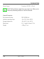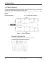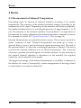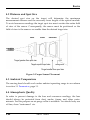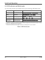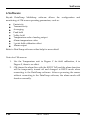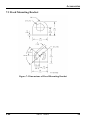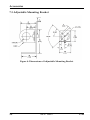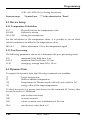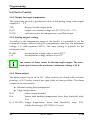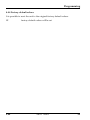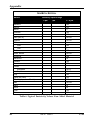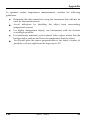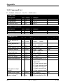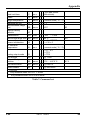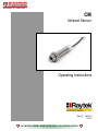
1
PO Box 1
Ilkley
West Yorkshire
Phone: 01943 602001
LS29 8EU
Fax: 01943 816796
innstrumentation
Website: www.issltd.co.uk
Email: [email protected]
Systems & Services
Ltd
CM
Infrared Sensor
Operating Instructions
Rev. B
i Tel: (01943) 602001- WWW.ISSLTD.CO.UK - Fax: (01943) 816796 i
06/2011
51101
The device complies with the requirements of the European
Directives.
EC – Directive 2004/108/EC (EMC)
Contacts
Raytek Corporation
Worldwide Headquarters
Santa Cruz, CA USA
Tel: +1 800 227 – 8074
(USA and Canada only)
+1 831 458 – 3900
Fax: +1 831 458 – 1239
[email protected]
European Headquarters
Berlin, Germany
Tel: +49 30 4 78 00 80
France
United Kingdom
[email protected]
[email protected]
[email protected]
Fluke Service Center
Beijing, China
Tel: +86 10 6438 4691
[email protected]
Internet: http://www.raytek.com/
Thank you for purchasing this Raytek product. Register today at
www.raytek.com/register to receive the latest updates, enhancements and
software upgrades!
© Raytek Corporation.
Raytek and the Raytek Logo are registered trademarks of Raytek Corporation.
All rights reserved. Specifications subject to change without notice.
WARRANTY
The manufacturer warrants this product to be free from defects in material
and workmanship under normal use and service for a period of two years
from date of purchase except as hereinafter provided. This warranty extends
only to the original purchaser. This warranty shall not apply to fuses or
batteries. Factory calibration is warranted for a period of one year. The
warranty shall not apply to any product that has been subject to misuse,
neglect, accident, or abnormal conditions of operation or storage. Should the
manufacturer be unable to repair or replace the product within a reasonable
amount of time, purchaser’s exclusive remedy shall be a refund of the
purchase price upon return of the product.
In the event of failure of a product covered by this warranty, the
manufacturer will repair the instrument when it is returned by the purchaser,
freight prepaid, to an authorized Service Facility within the applicable
warranty period, provided the manufacturer’s examination discloses to its
satisfaction that the product was defective. The manufacturer may, at its
option, replace the product in lieu of repair. With regard to any covered
product returned within the applicable warranty period, repairs or
replacement will be made without charge and with return freight paid by the
manufacturer, unless the failure was caused by misuse, neglect, accident, or
abnormal conditions of operation or storage, in which case repairs will be
billed at a reasonable cost. In such a case, an estimate will be submitted before
work is started, if requested.
THE FOREGOING WARRANTY IS IN LIEU OF ALL OTHER
WARRANTIES, EXPRESSED OR IMPLIED, INCLUDING BUT NOT
LIMITED TO ANY IMPLIED WARRANTY OF MERCHANTABILITY,
FITNESS, OR ADEQUACY FOR ANY PARTICULAR PURPOSE OR USE.
THE MANUFACTURER SHALL NOT BE LIABLE FOR ANY SPECIAL,
INCIDENTAL OR CONSEQUENTIAL DAMAGES, WHETHER IN
CONTRACT, TORT, OR OTHERWISE.
Content
1 Safety Instructions ................................................................................................. 8
2 Description ............................................................................................................ 10
3 Technical Data ...................................................................................................... 11
3.1 PARAMETERS .................................................................................................... 11
3.2 OPTICAL DIAGRAM.......................................................................................... 13
3.3 SCOPE OF DELIVERY ......................................................................................... 14
4 Basics ...................................................................................................................... 15
4.1 MEASUREMENT OF INFRARED TEMPERATURE ................................................ 15
4.2 DISTANCE AND SPOT SIZE ............................................................................... 16
4.3 AMBIENT TEMPERATURE ................................................................................. 16
4.4 ATMOSPHERIC QUALITY .................................................................................. 16
4.5 ELECTRICAL INTERFERENCE ............................................................................ 17
4.6 EMISSIVITY OF TARGET OBJECT ....................................................................... 17
5 Install and Operation .......................................................................................... 18
5.1 DIMENSIONS OF SENSOR .................................................................................. 18
5.2 MECHANICAL INSTALLATION ......................................................................... 19
5.3 CABLE ............................................................................................................... 19
5.4 WIRE CONNECTION ......................................................................................... 20
5.4.1 Analog output ...........................................................................................20
5.4.2 Alarm output.............................................................................................20
5.5 LED INDICATOR AND BLINK MODE ................................................................. 21
6 Software ................................................................................................................. 22
7 Accessories ............................................................................................................ 23
7.1 OVERVIEW ........................................................................................................ 23
7.2 FIXED MOUNTING BRACKET............................................................................ 24
7.3 ADJUSTABLE MOUNTING BRACKET ................................................................ 25
7.4 AIR PURGE COLLAR ......................................................................................... 26
7.5 RIGHT ANGLE MIRROR .................................................................................... 27
7.6 PROTECTIVE WINDOW ..................................................................................... 28
8 Programming ........................................................................................................ 29
8.1 GENERAL COMMAND STRUCTURE .................................................................. 29
8.2 DEVICE SETUP .................................................................................................. 30
8.2.1 Temperature Calculation ...........................................................................30
8.2.2 Post Processing .........................................................................................30
8.3 DYNAMIC DATA...............................................................................................30
8.4 DEVICE CONTROL ............................................................................................31
8.4.1 Output for target temperature .................................................................. 31
8.4.2 Analog output, scaling ............................................................................. 31
8.4.3 Alarm output ............................................................................................ 31
8.4.4 Factory default values ............................................................................... 32
9 Maintenance ..........................................................................................................33
9.1 TROUBLESHOOTING MINOR PROBLEMS ..........................................................33
9.2 ERROR CODES...................................................................................................34
9.3 AUTOMATIC ERROR INDICATION ....................................................................34
9.4 CLEANING THE LENS .......................................................................................34
10 Appendix .............................................................................................................36
10.1 DETERMINATION OF EMISSIVITY....................................................................36
10.2 TYPICAL EMISSIVITY VALUES.........................................................................36
10.3 COMMAND SET ..............................................................................................43
Safety Instructions
1 Safety Instructions
This document contains important information, which should be kept at all
times with the instrument during its operational life. Other users of this
instrument should be given these instructions with the instrument. Eventual
updates to this information must be added to the original document. The
instrument can only be operated by trained personnel in accordance with
these instructions and local safety regulations.
Acceptable Operation
This instrument is intended only for the measurement of temperature. The
instrument is appropriate for continuous use. The instrument operates
reliably in demanding conditions, such as in high environmental
temperatures, as long as the documented technical specifications for all
instrument components are adhered to. Compliance with the operating
instructions is necessary to ensure the expected results.
Unacceptable Operation
The instrument should not be used for medical diagnosis.
Replacement Parts and Accessories
Use only original parts and accessories approved by the manufacturer. The
use of other products can compromise the operational safety and
functionality of the instrument.
Instrument Disposal
Disposal of old instruments should be handled according to
professional and environmental regulations as electronic waste.
CM
Rev. B
06/2011
8
Safety Instructions
Operating Instructions
The following symbols are used to highlight essential safety information in
the operation instructions:
Helpful information regarding the optimal use of the instrument.
Warnings concerning operation to avoid instrument damage and
personal injury.
Pay particular attention to the following safety instructions.
Incorrect use of 110 / 230 V electrical systems can result in
electrical hazards and personal injury. All instrument parts
supplied with electricity must be covered to prevent physical
contact and other hazards at all times.
9
Rev. B 06/2011
CM
Description
2 Description
The CM miniature infrared sensors are high performance noncontact infrared
temperature measurement systems. They measure the amount of energy
emitted from an object accurately and repeatedly and convert the energy into
temperature signal.
The following analog outputs are available by different model:
0 to 5 Volt
J thermocouple
K thermocouple
The LED on the back of CM shows the status of units.
CM
Rev. B
06/2011
10
Technical Data
3 Technical Data
3.1 Parameters
Temperature range
-20 to 500°C (-4 to 932°F)
Spectral response
8 to 14 μm
Thermal Parameters
Accuracy1 (Digital and Voltage)
± 1.5% of reading or ± 2°C2
whichever is greater
Accuracy3 (TC)
± 1.5% of reading ±2°C or ± 4°C4
whichever is greater
Repeatability (Digital and Voltage)
± 0.5% of reading or ± 1°C
whichever is greater
Repeatability (TC)
± 0.5% of reading ± 1°C or ± 2°C
whichever is greater
Response time (95%)
150 ms
Temperature resolution
0.1°C (0.2°F)
Emissivity
0.100 to 1.100 (software controlled)
Transmissivity
0.100 to 1.000 (software controlled)
Electrical Parameters
Power
24 VDC ± 20% @ 20 mA
Analog Output
0 to 5 V or TCJ or TCK output
Digital Output
Two-way RS232 digital output
9600 baud, 8 data bits, 1 stop bit,
no parity, no flow control
1
2
3
4
for ambient temperature 23°C (73°F) ± 5 K , e = 0.95 and calibration geometry
± 3.5°C for Tmeas < 0°C (32°F)
for ambient temperature 23°C (73°F) ± 5 K , e = 0.95 and calibration geometry
± 5.5°C for Tmeas < 0°C (32°F)
11
Rev. B 06/2011
CM
Technical Data
Alarm Output
Transistor, 24 VDC @ 20 mA
RS232 TxD and Alarm output share one single wire. Either can be
selected by DataTemp software or ASCII command!
General Parameters
Environmental rating
IP65 (NEMA-4x)
Ambient operating range
-10 to 70°C (14 to 158°F)
Storage temperature
-20 to 85°C (-4 to 185°F)
Dimensions
Ø ¾”, length: 94 mm (3.7 in)
Weight
< 200 g (7.1 oz)
CM
Rev. B
06/2011
12
Technical Data
3.2 Optical Diagram
The optical diagrams indicate the target spot diameter at any given distance
between the target object and the sensing head.
All target spot sizes indicated in the optical diagrams are based on 90%
energy.
Optical resolution
13:1 @ 150 mm (90% energy)
Figure 1:Optical diagram
Calculating the Target Spot Size
To calculate the target spot size from two known points within an
optical diagram the following formula can be used:
Sx = unknown diameter of target spot
Sn = smallest known diameter of target spot
Sf = greatest known diameter of target spot
Dx = distance to unknown target spot
Dn = distance to smaller known target spot
Df = distance to greater known target spot
13
Rev. B 06/2011
CM
Technical Data
3.3 Scope of Delivery
Sensor
2 mounting nuts
Support software CD
Quickstart Guide
CM
Rev. B
06/2011
14
Basics
4 Basics
4.1 Measurement of Infrared Temperature
Everything emits an amount of infrared radiation according to its surface
temperature. The intensity of the infrared radiation changes according to the
temperature of the object. Depending on the material and surface properties,
the emitted radiation lies in a wavelength spectrum of approximately 1 to 20
μm. The intensity of the infrared radiation (”heat radiation”) is dependent on
the material. For many substances this material-dependent constant is known.
It is referred in Section 10.2 Typical Emissivity Values on page 36.
Infrared thermometers are optical-electronic sensors. These sensors are able to
detect ”radiation of heat”. Infrared thermometers are made up of a lens, a
spectral filter, a sensor, and an electronic signal-processing unit. The task of
the spectral filter is to select the wavelength spectrum of interest. The sensor
converts the infrared radiation into an electrical parameter. The connected
electronics generate electrical signals for further analysis. As the intensity of
the emitted infrared radiation is dependent on the material, the required
emissivity can be selected on the sensor.
The biggest advantage of the infrared thermometer is its ability to measure in
the absence of contact. Consequently, surface temperatures of moving or hard
to reach objects can easily be measured.
15
Rev. B 06/2011
CM
Basics
4.2 Distance and Spot Size
The desired spot size on the target will determine the maximum
measurement distance and the necessary focus length of the optical module.
To avoid erroneous readings the target spot size must contain the entire field
of view of the sensor. Consequently, the sensor must be positioned so the
field of view is the same as or smaller than the desired target size.
Best
Good
Incorrect
Target greater than spot size
Target equal to spot size
Background
Target smaller than spot size
Figure 2: Proper Sensor Placement
4.3 Ambient Temperature
The sensing head should work under ambient operating range in accordance
to section 3.1 Parameters, page 11.
4.4 Atmospheric Quality
In order to prevent damage to the lens and erroneous readings, the lens
should always be protected from dust, smoke, fumes, and other contaminants. For this purpose an air purge collar is available. You should only use
oil free, clean “instrument“ air.
CM
Rev. B
06/2011
16
Basics
4.5 Electrical Interference
To minimize electrical or electromagnetic interference, follow these
precautions:
Mount the sensor as far away as possible from possible sources of
interference such as motorized equipment producing large step load
changes.
Ensure a fully insulated installation of the sensor (Avoid ground
loops!).
Make sure the shield wire in the sensor cable is earth grounded at one
location.
4.6 Emissivity of Target Object
Determine the emissivity of the target object as described in appendix 10.1
Determination of Emissivity. If emissivity is low, measured results could be
falsified by interfering infrared radiation from background objects (such as
heating systems, flames, fireclay bricks, etc. close beside or behind the target
object). This type of problem can occur when measuring reflecting surfaces
and very thin materials such as plastic films and glass.
This measuring error when measuring objects with low emissivity can be
reduced to a minimum if particular care is taken during installation, and the
sensing head is shielded from these reflecting radiation sources.
17
Rev. B 06/2011
CM
Install and Operation
5 Install and Operation
5.1 Dimensions of Sensor
All sensors and accessories are supplied with 3/4-16 UNF-2A or
M18x1 thread.
Figure 3: Dimensions of sensor
CM
Rev. B
06/2011
18
Install and Operation
5.2 Mechanical Installation
All sensors come with a 1.0 m (3.3 ft) cable or 3.0 m (9.8 ft) and 2 mounting
nuts. You can mount the sensor in brackets or cutouts of your own design, or
you can use the mounting bracket accessories.
Figure 4: Sensor with fixed mounting bracket
5.3 Cable
The color code of the cable and 6 conductors are shown in the following table:
8
1
2
3
Outer
Jacket
Power
+
Power -**
RxD
J
brown
K
yellow
0 to 5 V
grey
orange
black
blue
4
TxD/
Alarm
violet
5
TC+/
mV+
6
TC-/
mV-
white
red
yellow
red
yellow
brown
7
Shield
** Die RS232’s Ground must be connected to Power-
Table 1: Sensor Wiring Color Code
19
Rev. B 06/2011
CM
Install and Operation
5.4 Wire Connection
Figure 5: Connection diagram
5.4.1 Analog output
There are 3 models available: 0 to 5 V, TCJ, TCK.
Minimum load impedance for 0 to 5 V output should be 50 kΩ.
Inner impedance of TC output circuit is 100 Ω.
5.4.2 Alarm output
RS232 TxD and alarm output share one single wire. Either can be selected by
the DataTemp software or RS232 command. When alarm mode is active, the
CM can receive command from a PC via RS232, but can’t respond to the PC.
RS232 TxD can work normally after the alarm output is switched off by
command K=0, see Section 10.3 Command Set. If unit is set by DataTemp
software, alarm output is valid only after the unit is restarted.
CM
Rev. B
06/2011
20
Install and Operation
5.5 LED indicator and blink mode
You can easily find the unit health status by the following LED blink mode:
status
LED-blink
LED-status
normal
slow blink 1
alarm
fast blink
○ ○ ○ ○ ○ ○ ○ ○
out of range
double blink
○ ○○○○○ ○ ○○○○○
unstable*
slow blink 2
○○○ ○○○ ○○○ ○○○
alarm fault**
always lighting
○
* unstable is typically caused by head ambient temperature fluctuations due to initial
warm up or thermal shock situations.
** alarm fault indicates the input of sensor’s alarm port is over current.
Table 2: LED blink mode
21
Rev. B 06/2011
CM
Software
6 Software
Raytek DataTemp Multidrop software allows the configuration and
monitoring of CM sensor operating parameters, such as:
Emissivity
Transmissivity
Averaging
Peak hold
Valley hold
Temperature scale of analog output
Alarm temperature value
1 point field calibration offset
Alarm output
Refer to DataTemp software online help for more detail.
Notes for CM sensors:
1.
2.
CM
Use the Temperature unit in Degree C for field calibration, if in
Degree F, there is no effect.
CM shares the alarm line with the RS232 TxD and the alarm function
will be temporarily turned off and changed to RS232 mode when
connecting to the DataTemp software. After re-powering the sensor
without connecting to the DataTemp software, the alarm mode will
function normally.
Rev. B
06/2011
22
Accessories
7 Accessories
7.1 Overview
Fixed Mounting Bracket
XXXCIACFB
Adjustable Mounting Bracket
XXXCIADJB
Air Purge Collar
XXXCMACAP
metrical: XXXCMACAPM
Right Angle Mirror
XXXCMACRA
metrical: XXXCMACRAM
Protective Window
XXXCMACPW
metrical: XXXCMACPWM
Adjustable Mounting Bracket
Air Purge Collar
Fixed Mounting Bracket
Protective Window
Right Angle Mirror
Figure 6: Overview of available accessories
23
Rev. B 06/2011
CM
Accessories
7.2 Fixed Mounting Bracket
Figure 7: Dimensions of Fixed Mounting Bracket
CM
Rev. B
06/2011
24
Accessories
7.3 Adjustable Mounting Bracket
Figure 8: Dimensions of Adjustable Mounting Bracket
25
Rev. B 06/2011
CM
Accessories
7.4 Air Purge Collar
The Air Purge Collar is used to keep dust, moisture, airborne particles, and
vapors away from the lens. It can be mounted before or after the bracket. It
has the push-in fitting. A 4 mm (0.16 in) outside diameter plastic tubing is
recommended to connect the fitting. Air flows into the fitting and out the
front aperture. The pressure of air should be 0.6 to 1 bar (8.7 to 15 PSI). Clean,
oil free air is recommended.
Figure 9: Dimensions of Air Purge Collar
CM
Rev. B
06/2011
26
Accessories
7.5 Right Angle Mirror
The Right Angle Mirror is used to turn the field of view by 90° against the
sensor axis. It is recommended when space limitations or excessive radiation
do not allow for direct alignment of the sensor to the target. The mirror must
be installed after the bracket and after the Air Purge Collar and screwed in
fully. In dusty or contaminated environments, air purging is required to keep
the mirror surface clean.
Figure 10: Dimension of Right Angle Mirror
When using the Right Angle Mirror, adjust the emissivity or
transmissivity settings downward by 5%. For example, for an
object with an emissivity of 0.65, you adjust the value down to
0.62. Or, you can keep the emissivity 0.65 and adjust the
transmissivity from 1.0 to 0.95. This correction accounts for
energy losses in the mirror.
27
Rev. B 06/2011
CM
Accessories
7.6 Protective Window
The protective window comes with Silicon as window material.
Determination of transmissivity of an unknown protective window:
If transmissivity of the measuring screen is not indicated on the data sheet,
you can also determine the transmissivity yourself. Please proceed as follows:
1. Measure the temperature of the target object with the sensing head,
without using the protective window. Note correct setting of
emissivity.
2. Insert the protective window in the sensing head.
3. Adjust the transmissivity in the software until the same temperature is
displayed, as it was determined without the protective window.
CM
Rev. B
06/2011
28
Programming
8 Programming
8.1 General Command Structure
Requesting a parameter
?E<CR>
“?“ is the command for “Request“
“E“ is the parameter requested
<CR> (carriage return, 0Dh) is closing the request.
Remark: It is possible to close with <CR> <LF> (0Dh 0Ah), but
<LF> (0Ah) is not necessary.
Setting a parameter (Poll Mode)
The parameter will be stored into the device flash memory.
E=0.975<CR> “E“ is the parameter to be set
“=“ is the command for “set a parameter“
“0.975“ is the value for the parameter
<CR> (carriage return, 0Dh) is closing the request
Remark: It is possible to close with <CR> <LF> (0Dh 0Ah), but
<LF> (0Ah) is not necessary.
Setting a parameter without writing it into the device flash memory.
This function is for test purposes only.
E#0.975<CR> “E“ is the parameter to be set
“#“ is the command for “set parameter without writing it into
the Flash“
“0.975“ is the value for the parameter
<CR> (carriage return, 0Dh) is closing the request.
Remark: It is possible to close with <CR> <LF> (0Dh 0Ah), but
<LF> (0Ah) is not necessary.
Device response format:
!E0.975<CR><LF> “!“ is the parameter for “Answer“
“E“ is the Parameter
“0.975“ is the value for the parameter
29
Rev. B 06/2011
CM
Programming
<CR> <LF> (0Dh 0Ah) is closing the answer.
Error message:
*Syntax Error
“*“ is the character for “Error“.
8.2 Device Setup
8.2.1 Temperature Calculation
U=C
E=0.950
XG=1.000
Physical Unit for the temperature value
Emissivity setting
Setting for transmission
For the calculation of the temperature value, it is possible to set an offset
(relative number to be added to the temperature value).
DO=-0.3
Offset adjustment -0.3 for the temperature signal
8.2.2 Post Processing
The following parameters can be set to determine the post-processing mode
P=5
F=12.5
G=10
maximum hold, hold time: 5 sec
minimum hold, hold time: 12.5 sec
averaging, average time (90%): 10 sec
8.3 Dynamic Data
To request the dynamic data, the following commands are available:
?T
?I
?XJ
?Q
Target temperature
Detector ambient temperature
Temperature of Thermocouple cold end (only valid for TC)
energy value of the target temperature
To check for resets (e.g. power shut down) use the command XI. Notice, after
a reset the unit is re- initialized.
?XI
!XI0
!XI1
asks for the reset status
no reset occurred
a reset occurred, new initialization of the unit
XI=0
sets the reset status back to 0
CM
Rev. B
06/2011
30
Programming
8.4 Device Control
8.4.1 Output for target temperature
The output can provide a predefined value of full analog range when signal
output is 0 … 5 V.
?XO
O=25
O=255
Request for the output mode
output of a constant voltage at 1.25 V (25% of 0 … 5 V)
switches back to the temperature controlled output
8.4.2 Analog output, scaling
According to the temperature range of the model, it is possible to set the
maximum voltage value according to a temperature value (e.g., the maximum
voltage 5 V shall represent 200°C). The same setting is possible for the
minimum value.
H=500
L=0
the maximum voltage value is set to 500°C
the minimum voltage value is set to 0°C
You cannot set these values for thermocouple output. The minimum span between the maximum / minimum settings is 20 K.
8.4.3 Alarm output
The alarm output can be set to N.C. (relay contacts are closed while in home
position) or N.O. (relay contacts are open while in home position). The alarm
output can be activated by:
Internal sensing head temperature
Target temperature
K=0
K=4
alarm output disabled
Sensor head ambient temperature lower than threshold, relay
N.O.
K= 2, XS=125.3 Target temperature lower than threshold, relay N.O.,
threshold setting to 125.3℃(if U=C is set)
31
Rev. B 06/2011
CM
Programming
8.4.4 Factory default values
It is possible to reset the unit to the original factory default values.
XF
CM
factory default values will be set
Rev. B
06/2011
32
Maintenance
9 Maintenance
Our customer service representatives are always at your disposal for any
questions you might have. This service includes any support regarding the
proper application of your infrared measuring system, calibration or the
solution to customer-specific solutions as well as repair.
In many cases your problems will be application-specific and can possibly be
solved over the telephone. So, if you need to return equipment to us, please
contact our Service Department before doing so. See phone and fax numbers
at the beginning of this document.
9.1 Troubleshooting Minor Problems
Symptom
No Output
Possible Cause
Solution
Cable disconnected
Check Cable Connections
Erroneous
Cable damaged
Temperature
Check Cable
Erroneous
Field of View Obstructed
Temperature
Remove the Obstruction
Erroneous
Lens Dirty
Temperature
Clean the Lens
Erroneous
Wrong Emissivity Setting
Temperature
Correct the Setting (Appendix)
Temperature
Wrong Signal Processing
Fluctuates
Correct Peak, Valley, or Average Settings
Temperature
Sensor not grounded
Fluctuates
Check Wiring/Grounding
Table 3: Troubleshooting
33
Rev. B 06/2011
CM
Maintenance
9.2 Error Codes
Output
Error Code Description
T>>>>>>
Temperature over range
T<<<<<<
Temperature under range
Table 4: Error Codes (via RS232)
9.3 Automatic Error Indication
The automatic error indication (alarm output) shall warn the user and
guarantee a secure output in the event of a system error. In the first place,
however, its task is to switch the system off in case of a faulty setup or a
defect in the sensing head or in the electronic circuits.
Never rely exclusively on the automatic error indication when
monitoring critical heating processes. It is strongly
recommended to take additional safety measures.
9.4 Cleaning the Lens
Care should be taken to keep the lens clean. Any foreign matter on the lens
will affect the accuracy of the measurements. Be sure to take care when
cleaning the lens. Please observe the following:
1.
2.
3.
Blow off loose particles with clean air.
Gently brush off remaining particles with a soft camel hair brush.
To remove any severe contamination, use a clean, soft cloth
dampened with distilled water. In any case, do not scratch the lens
surface!
For fingerprints or other grease, use any of the following:
Denatured alcohol
Ethanol
Kodak lens cleaner
CM
Rev. B
06/2011
34
Maintenance
Apply any of the above to the lens. Wipe gently with a clean, soft cloth until
you see colors on the lens surface, then allow to air dry. Never wipe the
surface dry - this may scratch the surface. If the lens is contaminated with
silicones (e.g. from hand creams), clean it carefully using Hexane. Allow the
lens to air dry.
Do not use any ammonia or any cleaners containing ammonia to
clean the lens. This may result in permanent damage to the lens’
surface.
35
Rev. B 06/2011
CM
Appendix
10 Appendix
10.1 Determination of Emissivity
Emissivity is a measure of an object’s ability to absorb and emit infrared
energy. It can have a value between 0 and 1.0. For example, a mirror has an
emissivity of 0.1, while the so-called “Blackbody“ reaches an emissivity value
of 1.0. If a higher than actual emissivity value is set, the output will read low,
provided the target temperature is above its ambient temperature. For
example, if you have set 0.95 and the actual emissivity is 0.9, the temperature
reading will be lower than the true temperature.
An object’s emissivity can be determined by one of the following methods:
1.
Determine the actual temperature of the material using an RTD (PT100),
a thermocouple, or any other suitable method. Next, measure the object’s
temperature and adjust emissivity setting until the correct temperature
value is reached. This is the emissivity for the measured material.
2.
For relatively low temperatures (up to 260℃, 500℉), place a plastic
sticker on the object to be measured. This sticker should be large enough
to cover the target spot. Next, measure the sticker’s temperature using an
3.
emissivity setting of 0.95. Finally, measure the temperature of an
adjacent area on the object and adjust the emissivity setting until the
same temperature is reached. This is the emissivity for the measured
material.
If possible, apply flat black paint to a portion of the surface of the object.
The emissivity of the paint must be above 0.98. Next, measure the
temperature of the painted area using an emissivity setting of 0.98.
Finally, measure the temperature of an adjacent area on the object and
adjust the emissivity until the same temperature is reached. This is the
emissivity for the measured material.
10.2 Typical Emissivity Values
The following table provides a brief reference guide for determining
emissivity and can be used when one of the above methods is not practical.
CM
Rev. B
06/2011
36
Appendix
Emissivity values shown in the table are only approximate, since several
parameters may affect the emissivity of a material. These include the
following:
1.
2.
3.
4.
5.
6.
7.
37
Temperature
Angle of measurement
Geometry (plane, concave, convex)
Thickness
Surface quality (polished, rough, oxidized, sandblasted)
Spectral range of measurement
Transmissivity (e.g. thin films plastics)
Rev. B 06/2011
CM
Appendix
METAL
Material
Emissivity/ Spectral range
3.9 µm
Aluminum
Unoxidized
Oxidized
Alloy A3003, Oxidized
Roughened
Polished
8 – 14 µm
0.02-0.1
0.2-0.4
0.3
0.1-0.3
0.02-0.1
Lead
Polished
Rough
Oxidized
0.05-0.1
0.4
0.2-0.6
0.02-0.2
Chromium
Iron
Oxidized
Unoxidized
Rusted
Molten
Iron, Cast
Oxidized
Unoxidized
Molten
Iron, Wrought
Dull
Gold
Haynes
Alloy
Inconel
Oxidized
Sandblasted
Electropolished
Copper
Polished
aufgeraut
CM
5 µm
0.5-0.9
0.05-0.2
0.5-0.7
—
0.6-0.95
0.2
0.2-0.3
0.9
0.01-0.1
0.3-0.8
0.7-0.95
0.3-0.6
0.15
0.03
0.05-0.1
Rev. B
06/2011
38
Appendix
METAL
Material
Emissivity/ Spectral range
3.9 µm
oxidiert
Magnesium
Brass
Polished
Burnished
Oxidized
Molybdenum
Oxidized
Unoxidized
Monel (Ni-Cu)
Nickel
Oxidized
Electrolytic
Platinum
Black
Mercury
Silver
Steel
Cold-Rolled
Ground Sheet
Polished Sheet
Molten
Oxidized
Stainless
Roughened
Oxidized
Titanium
Polished
Oxidized
Tungsten
Polished
Zinc
Oxidized
39
5 µm
8 – 14 µm
0.4-0.8
0.02-0.1
0.01-0.05
0.3
0.5
0.2-0.6
0.1
0.1-0.14
0.2-0.5
0.05-0.15
0.9
0.05-0.15
0.02
0.7-0.9
0.4-0.6
0.1
—
0.7-0.9
0.1-0.8
0.05-0.1
0.4-0.8
0.05-0.2
0.5-0.6
0.03
0.03-0.1
0.1
Rev. B 06/2011
CM
Appendix
METAL
Material
Emissivity/ Spectral range
3.9 µm
5 µm
Polished
Tin (Unoxidized)
8 – 14 µm
0.02
0.05
Table 5: Typical Emissivity Values
CM
Rev. B
06/2011
40
Appendix
NON-METAL MATERIAL
Material
Emissivity/ Spectral range
3.9 µm
5 µm
Asbestos
Asphalt
Basalt
Concrete
Ice
Paint (non-al.)
Gypsum
Glass
Plate
„Gob“
Rubber
Wood, Natural
Limestone
Karborund
Ceramic
Gravel
Carbon
Unoxidized
Graphite
Clay
Paper (any color)
Plastic (opaque, over 20 mils)
Salz
Sand
Snow
Cloth
Water
8 – 14 µm
0.95
0.95
0.7
0.95
0.98
0.9-0.95
0.8-0.95
0.85
—
0.95
0.9-0.95
0.98
0.9
0.95
0.95
0.8-0.9
0.7-0.8
0.95
0.95
0.95
0.9-0.98
0.9
0.9
0.95
0.93
Table 6: Typical Emissivity Values Non- Metal Material
41
Rev. B 06/2011
CM
Appendix
To optimize surface temperature measurements, consider the following
guidelines:
Determine the object emissivity using the instrument that will also be
used for the measurements.
Avoid reflections by shielding the object from surrounding
temperature sources.
For higher temperature objects, use instruments with the shortest
wavelength possible.
For translucent materials, such as plastic foils or glass, assure that the
background is uniform and lower in temperature than the object.
You should place the sensor perpendicular to the object’s surface (if
possible) or at any angle from the target up to 30°!
CM
Rev. B
06/2011
42
Appendix
10.3 Command Set
P ... Poll, B ... Burst, S ... Set, N ... Notification
FORMATSET
Description
Char Format P S Example
Poll parameter
?
?X
?T
Set parameter
=
X=...
E=0.85
Set without Save
#
X#
E#0.85
FORMAT RESPONSE
Description
Char Format P S Example
Acknowledge
!
!XXX
!T020.0
Error message
*
*Syntax error
COMMAND LIST
Description
Device adjustment
gain**
Device adjustment
offset **
Device special Info.
Char Format P S Legal values
Factory default
DG
n.nnnn
0.8000 … 1.2000
1
DO
nn.n
-20.0 … +20.0°C
0
DS
XXX
z.B. !DSRAY
DSRAY
0.95
Emissivity internal
E
n.nnn
Valley hold time
F
nnn.n
0.100 … 1.100
0.000 … 998.9 s
(999 = infinite)
Average time
G
nnn.n
0.100 ... 999 s
0
Top of mV range
H
nnnn.n
0 … 500°C
500
Sensor/head ambient
I
nnn.n
Relay alarm output
control
K
n
In current scale (°C/°F)
0=Alarm Off
1=Alarm On
2= Target, normal open
3= Target, normal close
4= Head, normal open
5= Head, normal close
6= Over current protect*
Bottom of mV range
L
nnnn.n
Output voltage***
O
nnn
43
-20 … 480°C
0-100=% of full range
255=controlled by unit
Rev. B 06/2011
0
-20
CM
Appendix
0.100~998.9 secs
(999=infinite)
Peak hold time
P
nnn.n
Power
Q
nnnnn
Target temperature
T
nnnn.n
In current scale (°C / °F)
Temperature unit
Device bottom range
limit
Restore factory
defaults
U
X
C/F
C
XB nnnn.n
-20°C
-20
Transmission
XG n.nnn
XF
0.100
Device high range limit XH nnnn.n
Sensor initialization
TC cold end
temperature
Analog output mode
0
XI n
XJ nnn.n
XO
… 1.000
500°C
1 = after RESET,
0 = if XI = 0
1
500
In current scale (°C / °F)
1 = 0 ... 5 V
2 = TCJ
3 = TCK
n
FW revision
Setpoint/Relay
function
XR
e.g. 1.000
XS nnnn.n
-17.2 … 497.2°C
Unit identification
XU nnnn.n
e.g.!CMLTV
497.2
Serial number
XV
e.g. 00012345
* Poll only
** only available when unit is in °C mode
*** only available when unit is in mV mode
Table 7: Command set
CM
Rev. B
06/2011
44