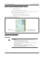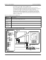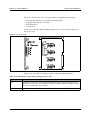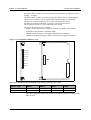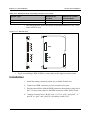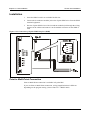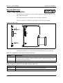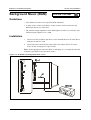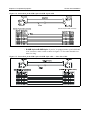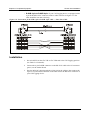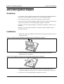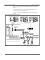
1
Panasonic Section 350 Installation Manual ! WARNING: This service information is designed for experienced technicians only and is not designed for use by the general public. It does not contain warnings or cautions to advise non-technical individuals of potential dangers in attempting to service a product. Products powered by electricity should be serviced or repaired only by experienced professional technicians. Any attempt to service or repair the product or products dealt with in this service information by anyone else could result in serious injury or death. This equipment is not designed for making emergency telephony calls when the power fails. Alternative arrangements should be made for access to emergency services. S-ICX Issued January 2000 The information contained in this document is subject to change without notice and should not be construed as a commitment by the Matsushita Communication Industrial Co. Ltd. (MCI). MCI reserves the right, without notice, to make changes to equipment design as advances in engineering and manufacturing methods warrant. The software and hardware described in this document may be used or copied only in accordance with the terms of the license pertaining to said software or hardware. Reproduction, publication, or duplication of this manual, or any part thereof, in any manner, mechanically, electronically, or photographically, is prohibited without permission of the Matsushita Communication Industrial Co. Ltd. (MCI). Copyright 2000 by Matsushita Communication Industrial Co. Ltd. (MCI) All rights reserved. Parts Supplied with CCU Following components are supplied and included in the box. CABLE TIE 10 PCS BATTERY LEAD 1 PC EMI FILTER 3 PCS CABLE TIE 3 PCS DDK CONNECTOR 4 PCS FOR 8 EXTENSION PORTS MANUAL (PRINTED) 1 PCE INSTALLATION MANUAL (UP TO CHAPTER 3) Note: CD-ROM manual which includes Operating manual, Installation manual and Programming manual is included in CPC card. Contents Chapter 1. Requirements ........................................... 1-1 Environmental Requirements ................................................................................................................ 1-1 Cleaning................................................................................................................................................. 1-2 Chapter 2. System Overview ..................................... 2-1 List of Components................................................................................................................................ 2-2 System Capacity and Specifications...................................................................................................... 2-3 Chapter 3. Cabinet Installation.................................. 3-1 Installation Location .............................................................................................................................. 3-1 Removing and Replacing the Cover ...................................................................................................... 3-2 Cabinet Installation................................................................................................................................ 3-2 Connecting the Main Cable ................................................................................................................... 3-4 Earthing.................................................................................................................................................. 3-4 Battery Backup (VB-44026UK) ............................................................................................................ 3-5 Chapter 4. Card Installation....................................... 4-1 Card Installation..................................................................................................................................... 4-1 About Marks Used in This Manual ....................................................................................................... 4-1 Card Installation Positions..................................................................................................................... 4-2 Special Integrated Slot 1 (IS1) ......................................................................................................... 4-3 Special Integrated Slot 2 .................................................................................................................. 4-3 SAEC/8, SAEC/4 (or SAPI in the future) Installation ..................................................................... 4-3 Maintenance Switches ........................................................................................................................... 4-4 CPU card: CPC-HS card (VB-44440UK), CPC-HM card (VB-44441UK) (CPC-HS/-HM) .......... 4-6 Exchange Lines...................................................................................................................................... 4-7 Loop Start Exchange Line card: LTRK/4 card (VB-44514UK), LTRK/8 card (VB-44510UK) (LTRK/4&8) ................. 4-7 T-Point ISDN Interface card: TBRI/4 card (VB-44530UK) (TBRI/4) .......................................... 4-10 T-Point ISDN Primary Rate Interface card: PRI/30 card (VB-44540UK) (PRI/30)...................... 4-13 SYNC Package/Network Unit: SYNC package (VB-44460) (SYNC) .......................................... 4-17 AC15 Tie Line Interface: AC15 card (VB-44570UK)................................................................... 4-19 ICX-10-350 S-ICX issued January 2000 iii Extensions............................................................................................................................................ 4-23 Digital Extension cards: (VB-44610UK/VB-44612UK/VB-44613UK) (DEC/8/16/24) ............. 4-23 Connecting Digital Key Telephones ............................................................................................. 4-26 Analog Proprietary Extension cards: SBS/A-series Proprietary Extensions (APEC/8) (VB-44660UK) .......................................................................................................... 4-27 Analog Extension cards: (VB-44620UK)(AEC/8) ....................................................................... 4-31 Special Analog Extension cards: SAEC/8 card (VB-44622UK)/ SAEC/4 card (VB-44621UK) (SAEC/8,SAEC/4) ... 4-31 BRI cards (S-point): S-point ISDN Basic Rate (VB-44630) (SBRI/4)......................................... 4-33 PRI cards (S-point): S-point ISDN Primary Rate (VB-44540UK) (SBRI/4) ............................... 4-37 8 DTMF Receiver Card: MFR/8 card (MFR/8) .................................................................................. 4-39 8 Party Conference Card: CONF card (VB-44120UK) (CONF) ........................................................ 4-40 ACD card: (VB-44140UK).................................................................................................................. 4-41 4-port Voice Processing card : (VB-44140UK) (VPU/4).................................................................... 4-42 Special API card : (VB-44132) (SAPI) ............................................................................................... 4-43 API card : (VB-44131) ........................................................................................................................ 4-44 Chapter 5. Peripheral Equipment.............................. 5-1 Music-On-Hold (MOH)......................................................................................................................... 5-1 Background Music (BGM) .................................................................................................................... 5-2 Paging .................................................................................................................................................... 5-3 PC Customization Tool.......................................................................................................................... 5-5 Call Logging Device.............................................................................................................................. 5-8 MIS Report Output .............................................................................................................................. 5-11 Application Interface (API) ................................................................................................................. 5-13 Headset ................................................................................................................................................ 5-15 Voice Recognition Adaptor ................................................................................................................. 5-16 Key Telephone Wall Mounting ........................................................................................................... 5-18 DSS ...................................................................................................................................................... 5-19 EM24 ................................................................................................................................................... 5-20 Doorphone Adaptor ............................................................................................................................. 5-21 1 Line SLT Adaptor............................................................................................................................. 5-24 Replacing the CPC Card’s Backup Battery ......................................................................................... 5-26 iv S-ICX issued January 2000 ICX-10-350 About This Manual Overview This manual provides installation instructions for the Small Integrated Communication eXchange (S-ICX). Please carefully observe the contents of this manual. The following table summarizes the purpose of each chapter. Chapter No. Title Purpose 1 Requirements 2 System Overview 3 Cabinet (CCU) Installation 4 Card Installation 5 Peripheral Equipment 6 Specifications Includes S-ICX model, information on the installation environment, and how to clean the S-ICX. Provides an overview of the S-ICX, including descriptions of the cabinet, system configurations, and unit cards. Explains how to prepare for CCU installation, how to remove and replace the CCU cover, install the battery, and install cards. Explains how to connect exchange lines and dedicated lines, how to connect different types of digital and analog internal lines, and how to mount telephones on the wall. Describes how to install and connect DSS units, doorphone adaptors, and other peripheral equipment; also describes how to replace the backup battery of the CPC card. Lists the specifications of the equipment constituting the S-ICX. Related Documents • For instructions on S-ICX programming, see Section 400: Programming. • For detailed descriptions of S-ICX operations, see Section 700: Feature Operation. ICX-10-350 S-ICX issued January 2000 v About This Manual vi Section 350-Installation S-ICX issued January 2000 ICX-10-350 Section 350-Installation Chapter 1. System Requirements Chapter 1. Requirements This chapter describes S-ICX model numbers, information on the installation environment, and instructions on how to clean the S-ICX. Environmental Requirements Temperature: The environment should be free from excessive temperatures in order to avoid component damage. Room temperature should be 32° to 104° Fahrenheit (0° to 40° Celsius). Humidity: The environment should be free from excessive humidity, which may rust metallic parts and degrade performance. Do not install the system where humidity could condense on its surfaces. Relative humidity should range between 30 and 90 percent. Ventilation: Adequate ventilation must be provided to allow upward air circulation through the cabinet grille. Gas and airborne particles: To avoid corrosion or oxidation of electrical contacts, the environment should be free from airborne particles and corrosive gas. Electrical noise: The environment should be free from excessive electrical noise, which could disturb the operation of digital circuits. The system should be located at least 10ft. (3m) away from welders, dimmers, or other high-current machines. Phones connected to the system should not be located near fluorescent lamps, air conditioners, washing machines, TVs, or radios. Vibration: The environment should be free from excessive vibration, which could loosen components. Water exposure: Because the S-ICX is an electrical device, exposure to water is dangerous. Do not place anything containing water on the system. Do not install under overhead plumbing, sprinkler system valves, or in areas that are susceptible to flooding. Lighting: Sufficient lighting is required for testing and maintenance. Lightning protection/grounding: The system must be properly grounded to protect it from lightning damage. • Supplemental and independent equipment grounding conductors are to be installed between the system and the wiring system ground. ICX-10-350 S-ICX issued January 2000 1-1 Chapter 1. System Requirements Section 350-Installation • One of the equipment grounding conductors must be a wire that is as thick or thicker than the ungrounded branch-circuit supply conductors. The equipment grounding conductor is to be installed as part of the circuit that supplies the system and is to be connected to a ground terminal at the service equipment. Bare, covered, or insulated grounding conductors should have a continuous outer finish that is green with yellow stripes. The equipment grounding conductor should be connected to a ground terminal at the service equipment. • The attachment-plug receptacles of the same type as that used by the systems that are in the vicinity of the S-ICX are all to be of a grounding type, and the equipment grounding conductors serving these receptacles are to be connected to earth ground at the service equipment. • A marking adjacent to the telecommunications jacks must instruct the user to connect grounding conductors for peripheral equipment before any telecommunication lines are connected to the product or system. Cleaning • Use a slightly damp cloth to clean the phones. The phones should never be cleaned with benzene, paint thinner, or other solvents. 1-2 S-ICX (Beta) issued December 1999 ICX-10-350 Chapter 2. System Overview Panasonic's Small Integrated Communication eXchange (S-ICX) is a hybrid telephone system capable of supporting up to 132 ports. The S-ICX cabinet includes the following: • Power Unit • Card Slots • Unit Cards (optional) • Backup Battery (VB-44026) (optional) • 8 DEC card (as integrated slot 1) Figure 2-1. The S-ICX CCU Card Slots Main Power Supply Unit Card Battery Backup Peripherals such as paging speakers, external music-on-hold sources, background music sources, PCs, printers, and Call Logging can be connected to the unit cards or the mother board. Figure 2-2 shows the exchange line and extension line connections as well as some peripheral connections. Exchange and extension line connections are covered in detail in Chapter 4. Peripheral connections are covered in detail in Chapter 5. ICX-10-350 S-ICX issued January 2000 2-1 Chapter 2. System Overview Section 350-Installation List of Components Table 2-1, 2-2, and 2-3 show the unit cards and packages that can be used with the SICX. Table 2-1. Unit card configuration Unit Type Unit Desig. CCU CAB-HD Main Cabinet Back-up Bat- BATT-S tery Unit Name Back-up Battery Page Product No. No. Unit Description 3-2 VB-44030UK Power Supply Unit and 8DEC are initially installed. 3-5 VB-44026UK Remarks Table 2-2. Unit card configuration Card Type Card Desig. Card Name Page Product No. No. Card Description Remarks Processor Cards CPC-HS CPC-HS Card (S-ICX only) 4-6 VB-44440UK Call processor card for 78-port system 32 Ext. CPC-HM CPC-HM Card (S-ICX only) 4-6 VB-44441UK Call processor card for 132-port system 64 Ext. Max. LTRK/8 Loop Start Exchange Line Card 4-7 VB-44510UK 8-port loop-start line LTRK/4 Loop Start Exchange Card (S-ICX only) 4-7 VB-44514UK 4-port loop-start line AC-15 AC15 4-19 VB-44570UK 4-port type AC-15 tie line exchange card Analog Exchange Lines Digital Exchange Lines TBRI/4 T-point BRI Card 4-10 VB-44530 T-point ISDN interface ports PRI/30 T/S-point PRI Card 4-13 VB-44540UK T-point ISDN primary interface port and S-point primary interface port Digital Extension DEC/8 Digital Extension Card 4-23 VB-44610UK 8-port digital extension card DEC/16 Digital Extension Card (S-ICX only) 4-23 VB-44612UK 16-port digital extension card Available for CPC-HM only. DEC/24 Digital Extension Card (S-ICX only) 4-23 VB-44613UK 24-port digital extension card Available for CPC-HM only. SBRI/4 S-point BRI Card 4-33 VB-44630 S-point ISDN interface ports PRI/30 T/S-point PRI Card 4-37 VB-44540UK T-point ISDN primary interface port and S-point primary interface port APEC/8 SBS Extension Interface Card 4-27 VB-44660UK Interface card for SBS proprietary key telephone SAEC/4 Special Analog Extension unit(S-ICX only) 4-31 VB-44621UK 4-port analog extension card includ- For IS2 ing ringer circuit for IS2 slot SAEC/8 Special Analog 4-31 Extension Card (S-ICX only) VB-44622UK 8-port analog extension card includ- For IS2 ing ringer circuit for IS2 slot AEC/8 Analog Extension Card 4-31 VB-44620UK 8-port analog extension card includ- For FS1 to FS5 ing ringer circuit DTMF Circuits MFR/8 8 DTMF Receiver Card 4-39 VB-44110UK 8-circuit DTMF receiver Interface cards API API Card 4-44 VB-44131 Applications Processor Interface card Data for External Integrated VM or ACD products (FOR FUTURE USE) SAPI Special API Unit (S-ICX only) 4-43 VB-44132 Internal Application Processor Interface unit For IS2 Data for External Integrated VM or ACD products (FOR FUTURE USE) CONF 8-Party Conference Card 4-40 VB-44120UK Interface card for 8-party conference interface VPU/4 Voice Processing Card/4 4-42 VB-44160UK Voice processing card for Built-in ACD voice ACD ACD Card 4-41 VB-44140UK Built-in ACD unit Analog Extension Audio applications 2-2 S-ICX issued January 2000 ICX-10-350 Section 350-Installation Chapter 2. System Overview Card Type Card Desig. Card Name Page Product No. No. Daughter package SYNC Sync. Package/Network Unit 4-17 VB-44460UK Card Description Remarks Network sync circuit unit Mounts on CPC-HS or CPC-HM card. Table 2-3. Terminal Equipment configuration Terminal Type Terminal Terminal Name Desig. Phone System TEL Page No. Product No. 12 Key Standard 4-26 VB-D411UK(B) TEL 12 Key Display Speakerphone 4-26 VB-D411DSUK(B) TEL 12 Key Large Display Speakerphone 4-26 VB-D411LDSUK(LDSUB) TEL 12 Key Display Soft key Phone 4-26 VB-D411DSVUK TEL 24 Key Display phone 4-26 VB-D611DUK TEL 24 Key Display Speakerphone 4-26 VB-D611DSUK(B) DSS DSS 5-19 VB-D631UK(B) EM24 EM24 5-20 VB-D331UK VRADP Voice Recognition Adaptor 5-16 VB-44101UK SLTADP One Line SLT Adaptor 5-24 VB-43702UK 5-21 VB-3473UK DPH-ADP Doorphone Adaptor Terminal Description Remarks System Capacity and Specifications Table 2-4, 2-5, and 2-6 shows the Maximum System Capacities and Specifications. Table 2-4. System Capacity With CPC-HS With CPC-HM Exchange line ports Analog exchange AC15 BRI Circuits PRI 8x4+30=62 (including one PRI30) 40 20 20 30 8x3+30x2=84 (including two PRI30s) 40 20 20 60 Extension ports Proprietary telephone 2 wire telephone (SLT) DSS consoles 32 24 (8 initially installed) 24 (including SAEC/8) 4 64 56 (8 initially installed) 48 (including SAEC/8) 4 3 party conference 8 8 DTMF circuits 12 (4 initially installed) 12 (4 initially installed) Paging Group Internal External 10 (72 members 1 (5 relays) 10 (72 members 1 (5 relays) Speed Dial (Max 24 digits) System Personal 800 20 800 20 Grouping Operator Group Hunting Group Tenant Group MCO Group Pick upGroup 1 (20 members) 12 (20 members) 12 99 12 (20 members) 1 (20 members) 12 (20 members) 12 99 12 (20 members) Camp-on (System Basis) 150 150 Call Back Internal (system) External (System) 32 32 32 32 Call Forward All (system) Busy (system) No Answer (system) 144 144 144 144 144 144 ICX-10-350 S-ICX issued January 2000 2-3 Chapter 2. System Overview Section 350-Installation With CPC-HS With CPC-HM Class of Service Internal External 16 16 16 16 TRS Class 50 50 ISDN Related Features DDI numbers (A/B) MSN 96 96 96 96 Account Code (Verified) 500 (10 digits) 500 (10 digits) Absence Message 10 (16 digits) 10 (16 digits) Text Message 10 (16 digits) 10 (16 digits) Table 2-5. Dimensions and Weight S-ICX Power Consumption CCU Proprietary tel 336VA 2.7W Dimensions (cm) CCU Proprietary tel W:360 x H:450 x D:220 W:186 x H:90 x D:233 Weight (kg) CCU Proprietary tel 7 Kg 1 Kg Table 2-6. Telephones can be connected to S-ICX Interface Card Type VB-44660 APEC/8 •– Model of Telephones con- A series telephone nected via interface card VA-30920 VA-12020 VA-12022 •– 2-4 VB-44660 APEC/8 •– VB-44610 DEC/8 VB-44612 DEC/16 VB-44613 DEC/24 SBS telephones VB-9211 VB-9211DS VB-9411 VB-9411DS VB-9411ADS DBS/ICX telephones VB-3411 VB-3411DS VB-3411LDS VB-3611D VB-D411 VB-D411DS VB-D411DSV VB-D411LDS VB-D611D VB-D611DS Note: Some features may not be available due to limitations of legacy equipment. S-ICX issued January 2000 ICX-10-350 Section 350-Installation Chapter 2. System Overview Figure 2-2. System Connections ICX-10-350 S-ICX issued January 2000 2-5 Chapter 2. System Overview 2-6 Section 350-Installation S-ICX issued January 2000 ICX-10-350 Chapter 3. Cabinet Installation This chapter explains how to prepare for a single cabinet installation, how to remove and replace the cabinet cover, and how to install the battery, power supply, and cards. Installation Location CAUTION: • Turn the power switch and the external breaker OFF, and disconnect the AC cable before removing any covers. Guidelines • Before deciding where to install the single base cabinet, check the external dimensions shown below, the area required for maintenance, and the "Environmental Requirements" on page 1-2. Figure 3-1. Single Base Cabinet dimensions and maintenance area Notes: -Hatched area ICX-10-350 indicates the area that should be provided for maintenance. S-ICX issued January 2000 3-1 Chapter 3. Cabinet Installation Section 350-Installation Removing and Replacing a Cover 1. Unscrew the front cover. 2. Pull the bottom of the front cover outward . Note: Do not exert excessive force when pulling out the bottom of the front cover as doing so may damage the claw slots. 3. Gently lift the cover off by sliding it up and away. 4. To replace the cover, repeat above in a reverse order. Figure 3-2. Removing and replacing a Cover Holding Screw Pull the front cover out at bottom, then lift Cabinet Installation Guidelines CAUTION: • Turn the power switch OFF, and make certain the AC cable is disconnected before installing the cabinet. • Handle the cabinet carefully to avoid damage. • The cabinet should be secured to a wall so that it does not topple in the event of earthquake, etc. • Remove cabinet cover before installation (see page 3-2). • If backup batteries have already been placed into the guides, remove them from the cabinet before installing. 3-2 S-ICX issued January 2000 ICX-10-350 Section 350-Installation Chapter 3. Cabinet Installation Preparation 1. Hold the cabinet against the wall. Using a pen or pencil, mark the center of the wall visible through the top retaining screw holes on the cabinet’s back plate and the lower center screw. 2. Mount the 2 wall-mounting screws (4 mm flat head screws recommended) using the marks on the plywood as a guide (32 cm apart). Leave approximately 2.5 cm of the screws protruding out of the wall. 3. Insert the pointed end of the tie-wrap into the top hole located on the top left side of the back plate, shown in Figure 3-4. When the tie-wrap has passed through the back plate, bend it down and push it back through the other hole in the back plate (and PCB). 4. Lift the back plate, and hook it onto the screws. 5. Completely tighten the screws. Figure 3-3. Wall-Mounting Installation: Attaching the wall-mounting of cabinet #1 Insert Tie-wrap here. Pull tie-wrap back through here. Holding Screw ICX-10-350 S-ICX issued January 2000 3-3 Chapter 3. Cabinet Installation Section 350-Installation Connecting the AC Cable Use BS1363 approved AC plug. For pluggable equipment, that the socket-outlet shall be installed near the equipment and shall be easily accessible. If a device other than a 13 Amp plug top is used as a disconnection device it must incorporate an all pole disconnection device. The wires in this mains lead are coloured in accordance with the following code: Green - and -yellow . . . . . . . . . . . . . . . .Earth (E) Blue. . . . . . . . . . . . . . . . . . . . . . . . . . . . .Neutral (N) Brown . . . . . . . . . . . . . . . . . . . . . . . . . . .Live (L) As the colours of the wires in the mains lead of this equipment may not correspond with the coloured markings identifying the terminals in your connector proceed as follows: The wire which is coloured green - and - yellow must be connected to the terminal which is marked by the letter E or by the safety earth symbol or coloured either green or green - and - yellow. The wire which is coloured blue must be connected to the terminal which is marked with the letter N or coloured black. The wire which is coloured brown must be connected to the terminal which is marked with the letter L or coloured red. This equipment must be earthed when it is connected to an AC mains outlet. Grounding Guidelines CAUTION: • Turn the power switch OFF, and make certain the AC cable is not plugged in before grounding the cabinet. • Be sure to attach an EMI filter to the AC cable to reduce interference. • For safety reasons, the S-ICX must remain grounded at all times. For permanent connection a readily accessible disconnect device shall be provided. If connection is made by domestic plug, the socket shall be near the equipment and shall be easily accessible. • The service ground cable must be 14 AWG minimum. It is recommend that the ground cable at least 12 AWG (stranded). • Resistance to ground must be 0.1 Ohms or less. Installation 1. Connect a permanent connection from the building service ground using a grounding wire to safety earth on the cabinet chassis. See Figure 3-4. 2. Install an EMI filter on the AC cable. 3-4 S-ICX issued January 2000 ICX-10-350 Section 350-Installation Chapter 3. Cabinet Installation Figure 3-4. Grounding the Master Cabinet Safety Grounding Chassis Grounding Battery Backup (VB-44026UK) Guidelines CAUTION: • Turn the power switch and the external breaker OFF, and disconnect the AC cable before installing the backup battery. • Carefully note the polarity of the batteries to prevent shorting. • Replace only with the same or equivalent type recommended by the manufacturer. Dispose of used batteries according to the manufacturer’s instructions. • The battery cable must be at least 18 AWG. • During normal conditions, the backup batteries last for about 15 minutes. • The backup batteries should be replaced about every 3 years. Installation 1. ICX-10-350 Connect the red +24V cable to the + terminal of battery A. S-ICX issued January 2000 3-5 Chapter 3. Cabinet Installation Section 350-Installation 2. Connect the blue GND cable to the - terminal of battery B. 3. Using the supplied battery cable connect the blue to the - terminal of battery A and red to the + terminal of battery B. 4. Slide the batteries into the guides in the cabinet. Figure 3-5. Installation of Backup Batteries (VB-44026UK) This lead is supplied with a CCU. Battery (VB-44026UK) 3-6 S-ICX issued January 2000 ICX-10-350 Chapter 4. Card Installation This chapter explains how to connect ecxhange lines, how to connect different types of digital and analog extensions. Card Installation CAUTION: • With the exception of selected cards as described in ’Maintenance Switches’ on page 4-4, many cards require power to be OFF before installing or removing the cards. Turn the power switch OFF and make certain the AC cable is disconnected before installing cards. • Push the cards in so that they are securely seated. Failure to do so may result in the card being damaged or incorrect operation. The card circuits include CMOS-ICs, which are susceptible to damage by static electricity. • To avoid damaging the CMOS-ICs, observe the following precautions when handling the cards: 1) Touch a ground or the metal cabinet frame to discharge any static that may have built up on your body. 2) Do not directly touch the CMOS-ICs or electrical conductors. 1. With the lettering on the card pointing up, slide the card into the guide of the card slot in the cabinet. 2. Hold the card on the top and bottom edges with both hands and carefully push it into the slot. 3. When the connector row at the far end of the card touches the corresponding connector on the unit, press the card in more firmly until it is seated. 4. Repeat steps 1 through 3 for all other cards. About Marks Used in This Manual XXXXX card Card names shown at the side of function titles indicate cards that must be mounted to enable connections. Cards marked with an at the side of the card name indicate that the card must not be removed or inserted while the power is ON. For details on removing and inserting cards, refer to "Maintenance Switches" on page 4-4. ICX-10-350 S-ICX issued January 2000 4-1 Chapter 4: Card Installation Section 350-Installation Card Installation Positions The unit cards are installed in the card slots in the S-ICX cabinet. Card Installation Positions in a system are shown below: Figure 4-1. Card Installation Positions Slot Card CPC CPC-HS,CPC-HM FS1 to FS5 Trunks Extensions FS4 Digital TBRI/4, PRI/30 Analog LTRK/4, LTRK/8, AC15 Digital DEC/8, DEC/16, DEC/24, SBRI/4, PRI/30 Analog APEC/8, AEC/8 Options/Audio MFR/8, CONF Applications VPU/4 FS5 ACD IS2 SAEC/4, SAEC/8, SAPI IS2 IS2 4-2 S-ICX issued January 2000 SAEC/4 or SAEC/8 (or SAPI in the future) SAEC/4, SAEC/8 or SAPI ICX-10-350 Section 350-Installation Chapter 4: Card Installation Special Integrated Slot 1 (IS1) 8 DEC circuits are integrated on a mother board with DDK connectors as shown above. These 8 DEC circuits are regarded as Integrated Slot(IS1) for programming only, there is no actual card slot. Special Integrated Slot 2 The special integrated slot 2 (IS 2) is built into the mother board with a connector. The slot is reserved only for one SAEC/4, SAEC/8 or SAPI cards. Figure 4-2. Special integrated slots. CPC Card Free Slots Special Slot (IS 2) DDK connectors for 8 DEC circuits (IS1) P10 P11 P1 A B A B 5 6 7 8 P5 Locking tab 43 21 B A BA SAEC/4, SAEC/8 and SAPI Installation ICX-10-350 1. Remove the locking tab, located in the upper right corner, from the special IS 2 slot. 2. Slide the SAEC/4, SAEC/8 or SAPI card three-quarters of the way into the slot. 3. Attach the card ribbon cable to the connector on the backplane. 4. Slide the card into the slot until secure. 5. Reattach the special slot locking tab. S-ICX issued January 2000 4-3 Chapter 4: Card Installation Section 350-Installation Maintenance Switches Guidelines CAUTION: • Check that the line busy lamp is off before removing the card. If the lamp is on, the line will be disconnected when the card is removed. • Check that the maintenance switch is off. After replacing the card in its slot on completion of the maintenance work. • Never attempt to remove any of the following cards while the system is operating: • CPC-HS card, CPC-HM card • VPU/4 card • ACD card • API card, SAPI card • SAEC/4 card, SAEC/8 card • The following cards can be removed from and replaced in their slots even when the system is operating (power is on) provided the maintenance switch is set to ON (up). • LTRK/8 card, • TBRI/4 card, •LTRK/4 card, •PRI/30 card •AC15 card • When the maintenance switch is on, the cards are in the following state: • Incoming calls are ignored; • Outgoing calls are prevented; • The line is disconnected on completion of any current call. So, additional incoming calls are ignored and outgoing calls are prevented as soon as any current call is completed. The cards can be removed as soon as all circuits on the card are idle and the busy lamps are off. Note: The cards for extension line (DEC/8, DEC/16, DEC/24, AEC/4, AEC/8, APEC, SBRI/4, MFR/8, and CONF Card) can be removed and replaced while the system is operating. Because there are no busy lamps for calls on extension lines, however, you cannot check the status of these lines. It is recommended that you announce using paging, before removing the cards, to warn users that the lines will be disconnected. 4-4 S-ICX issued January 2000 ICX-10-350 Section 350-Installation Chapter 4: Card Installation Figure 4-3. Maintenance Switch positions (LTRK/4 card shown) • Cards for the following extension lines can be removed and replaced while the system is operating. • DEC/8 card, • AEC/8 card • CONF card • DEC/16 card, • SBRI/4 card • APEC/8 card • DEC/24 card • MFR/8 card Note:Because there are no busy lamps for calls on extension lines, you cannot check the status of these lines. We recommend using paging, before removing the cards, to warn users that the lines will be disconnected. ICX-10-350 S-ICX issued January 2000 4-5 Chapter 4: Card Installation Section 350-Installation CPU card CPC-HS card (VB-44440UK), CPC-HM card (VB-44441UK) CPC-HS/-HM The CPC-HS card is a standard CPU card for systems supporting up to 32 extensions, and up to 78 ports. This card incorporates a 16-bit CPU. The CPC-HM card is a high-level CPU unit for a system with up to 64 extensions, and up to 132 ports. The CPC card provides a time switch (9 HW x 9 HW), time switch, 4 sets of 3-party conference circuits, service tone, a DTMF transmitter, an input terminal for external Music-On-Hold and BGM source (RCA jack), EPA output (RCA jack), a connecting terminal for synchronization package (VB-44460UK), and an interface connector for a compact flash card. The system control program is downloaded to the internal memory of the system through the compact flash card. Memory is retained with a backup battery. Figure 4-4. CPC-HM card (ERA) (MOH) CPC-HS has only one socket. Note: CPC-HS does not have a BGM socket. A MOH socket is used for both BGM. R351 = EPA output impedance (600Ω/high-impedance) setting (page 5-5) 4-6 S-ICX issued January 2000 ICX-10-350 Section 350-Installation Chapter 4: Card Installation The following tables show switch settings and LED indicators for the CPC card. Table 4-1. Switch settings of CPC card SW No. S1 : Black (MODE) S2 : Red (RESET) S3 : (CODE) S4 : (RAM HOLD) Description Push switch for setting modes of system. Push switch for resetting. Rotary switch for setting startup mode of system. Switch for selecting battery backup of memory. Table 4-2. LED indications of CPC card LED indication (RUN) (MJ) (MN) Description Flashes red when Main Processing Unit (MPU) is operating. Turns ON red when Major (MJ) alarm is detected. Turns ON red when Minor (MN) alarm is detected. Exchange Lines The following cards are used with exchange lines: • LTRK/8: Loop start exchange line interface card (8 ports) • LTRK/4: Loop start exchange line interface card (4 ports) • TBRI/4: T-point ISDN basic interface card (4 ports) • PRI/30: T-point and S-point ISDN primary rate interface card (1 port) • AC15/4: AC-15 tie line interface card (4 ports) Install the correct type of cards in the CCU for the exchange lines that are to be connected, then connect the exchange lines. Loop Start Exchange Line card LTRK/4 card (VB-44514UK) LTRK/8 card (VB-44510UK) LTRK/4&8 Guidelines • Loop Start exchanges are connected to a LTRK/4 card(VB-44514UK) or LTRK/8 card(VB-44510UK) installed in a flexible slot of the CCU. The LTRK/4 card provides for maximum of 4 exchange lines, and the LTRK/8 card provides 8 exchange line connections. ICX-10-350 S-ICX issued January 2000 4-7 Chapter 4: Card Installation Section 350-Installation • The maintenance switch(SW1) on the LTRK/4 or LTRK/8 card can be set so that the card can be removed and installed while the systenm is operating. See page 42 for details on the maintenance switch. • Table 4-1 shows the maximum numbers of cards and exchanges per system type. Table 4-3. Maximum Loop Start Exchanges per system System Type Maximum Number of Cards Maximum No. of Loop Start Exchange Lines 78 ports (CPC-HS) 5 1-40 132 port (CPC-HM) 5 1-40 The LTRK/8 card provides an 8 exchange line interface. It provides a lightening arrestor and a safety circuit to directly connect with general telephone lines. The LTRK/4 card provides an 4 exchange line interface. It provides a lightening arrestor and a safety circuit to directly connect with general telephone lines. Figure 4-5. LTRK/8 card The following tables show switch settings and LED indications for the LTRK/4 card. 4-8 S-ICX issued January 2000 ICX-10-350 Section 350-Installation Chapter 4: Card Installation Table 4-4. Maintenance switch (SW1) settings of LTRK/8 card Setting Description ON Card is in closed status, and can be mounted and removed when power is ON. (Sending/receiving of calls is disabled. If this is set during speech, sending/receiving of calls is disabled after the call ends.) OFF (M-SW) Normal operation (This switch is set to OFF for normal operation.) Table 4-5. LED indications of LTRK/8 card LED indication Description LED1 (LINE BUSY) Turns ON when any exchange line on the card is in use. Table 4-6. Pinout of DDK connector (CN3) on LTRK/8 card CN No. CN2 Line No. (DDK No.) 1 2 4 3 4 1 2 3 3 4 1 2 2 3 4 1 2 1 3 4 Pin No. 1 2 3 4 5 6 7 8 9 10 11 12 13 14 15 16 Exchange Line No. 8 7 6 5 4 3 2 1 Signal B A B A B A B A B A B A B A B A Installation 1. Install the LTRK/4 or LTRK/8 card in any available flexible slot. 2. Connect one DDK connector per two exchange lines. 3. Pass the exchange lines with the DDK connectors through the wiring slot in the CCU and connect them to the DDK connector on the LTRK/4 or LTRK/8 card. 4. Connect FG(CCU) with LTRK/4 or LTRK/8 card using a screw and washer. ICX-10-350 S-ICX issued January 2000 4-9 Chapter 4: Card Installation Section 350-Installation Figure 4-6. Connecting loop-start exchange lines T-Point ISDN Interface card TBRI/4 card (VB-44530UK) TBRI/4 Guidelines • T-point ISDN Basic Rate is accommodated by the TBRI/4 card which is installed in a flexible slot. Four T-point ISDN lines can be connected to each TBRI/4 card. • T-point ISDN is connected via a Network Termination Unit (NT1). • T-point ISDN is connected to the TBRI/4 card using RJ-45 connector. See Figure 4-4 for the pin configuration of the RJ-45 connectors. • The TBRI/4 card can be attached or detached when the power is turned ON by setting the maintenance switch (SW4). See page 4-4 for details. • When using T-point ISDN, you must install the synchronization package (VB44460UK) on a CPC-HS or CPC-HM card. • Table 4-3 shows the maximum number of cards that can be installed with each CPC size. 4-10 S-ICX issued January 2000 ICX-10-350 Section 350-Installation Chapter 4: Card Installation Table 4-7. Maximum Number of T-Point ISDN interfaces per system System Type (Processor) Maximum Cards Maximum Lines (No. of channels) 78 ports (CPC-HS) 5 20/(40ch) 132 ports (CPC-HM) 5 20/(40ch) Figure 4-7. TBRI/4 card Table 4-8. Maintenance switch (SW2) settings of TBRI/4 card Setting Description ON Card is in closed status, and can be mounted and removed when the power is ON. (Sending/receiving of calls is disabled. If this is set during speech, sending/receiving of calls is disabled after speech ends.) OFF Normal operation (This switch is set to OFF for normal operation.) Table 4-9. LED indication of TBRI/4 card Switch position LED indication 0 OFF (default setting when unit is shipped) 1 1st interface condition displayed by LAYER1 LED and LAYER2 LED 2 2nd interface condition displayed by LAYER1 LED and LAYER2 LED 3 3rd interface condition displayed by LAYER1 LED and LAYER2 LED 4 4th interface condition displayed by LAYER1 LED and LAYER2 LED 5 to 9 ICX-10-350 Not available S-ICX issued January 2000 4-11 Chapter 4: Card Installation Section 350-Installation • Circuit select switch (SW1) settings of TBRI/4 card SW1 of the TBRI/4 enables you to display the status of the each interface condition using LAYER1 LED (lights in red when synchronization is completed) or LAYER2 LED (lights in red when DL (Data Link) is completed). Four lines on one single card are connected to an ISDN of the same station. Therefore, the remaining synchronizations are automatically completed when synchronization has been completed in any one of the lines. Table shows the settings of the line selection switch. Line Selection Switch (SW1: SELECT) on TBRI/4 card TBRI/4 card. Table 4-10. LED indication of TBRI/4 card LED indication Description LED1 (LINE BUSY) Turns ON when exchange line is in use. LED2 (SYNC) Turns ON when network synchronisation clock is sent. LED3 (LAYER1) Turns ON when synchronisation is established. LED4 (LAYER2) Turns ON when data link (DL) is established. Figure 4-8. Connection of T-Point ISDN Interface (BRI) Connector (RJ45) RJ45 cable 4-12 S-ICX issued January 2000 ICX-10-350 Section 350-Installation Chapter 4: Card Installation TPRI/30 T-Point ISDN Interface card TPRI/30 card (VB-44540UK) Guidelines • The T-point ISDN primary rate interface is accommodated on the PRI/30 card which is installed in a flexible slot. You can connect one T-point ISDN primary rate interface carrier to each PRI/30 card. • By setting the switch and reprogramming, the PRI/30 card can also be set up as an S-point ISDN primary rate or Q-SIG interface. • The T-point ISDN primary rate interface connects to the switched network via a subscriber unit. • Depending on Dip switch SW2-2, the PRI/30 card can be set for "8-channel mode" or "Other mode". When set for "Other mode" by Dip switch, you can also specify three channel classifications: "1 to 16B+D", "1 to 24B+D"or "1 to 30B+D" by system configuration programming. Table 4-11 shows the mode settings of the PRI/30 card. Table 4-11. Mode Settings of PRI/30 card Card Name Switch Setting Mode PRI/30 card (Primary Rate Interface) 8ch mode Card Assignment/ No. of Channels Used PRIT/8: 1 to 8B+D PRIT/16: 1 to 16B+D PRIT/24: 1 to 24B+D PRIT/30: 1 to 30B+D Other mode • The T-point ISDN primary rate interface carrier line uses an 8-conductor modular connector RJ45 connected to the PRI/30 card. See Figure 4-5 on page 4-8 for the pin configuration of the 8-conductor modular connectors. • The PRI/30 card can be attached or detached when the power is turned ON by setting the maintenance switch (SW3). See page 4-4 for details. • When installing a T-point ISDN primary rate interface, install the synchronization package on the CPC-HS or CPC-HM card. • The following table shows the maximum number of T-point ISDN primary rate interfaces that can be installed in each system size. Table 4-12. Maximum number of T-Point Primary Rate Interface cards per system System Type Maximum Cards No. of B-channels 78 ports (CPC-HS) 1 30ch x 1=30ch 132 ports (CPC-HM) 2 30ch x 2=60ch 78 ports (CPC-HS) 5 8ch x 5=40ch 132 ports (CPC-HM) 5 8ch x 5=40ch ICX-10-350 S-ICX issued January 2000 4-13 Chapter 4: Card Installation Section 350-Installation Figure 4-9. PRI/30 card Table 4-13. Maintenance switch (SW3) settings of PRI/30 card Setting ON OFF Description Card is in closed status, and can be mounted and removed when power is ON. (Sending/receiving of calls is disabled. If this is set during speech, sending/receiving of calls is disabled after speech ends.) Normal operation (This switch is set to OFF for normal operation.) Installation of Sync. Package 4-14 1. Align the connector (P1) of the CPC-HS or CPC-HM card with the holes of spacers and connect the SYNC synchronization package. See Figure 4-12 on page 4-18 for how to install the SYNC synchronization package. 2. Insert the CPC-HS or CPC-HM card in the specified slot. 3. Set the DIP switch (SW2-1) of the PRI/30 card ON (exchange). 4. Set the DIP switch (SW2-2) of the PRI/30 card as shown in Table 4-6. S-ICX issued January 2000 ICX-10-350 Section 350-Installation Chapter 4: Card Installation Table 4-14. Switch setting for SW2 on PRI/30 Card Switch No. Function SW2-1 ON Set to "Exchange" for T-point. OFF Set to "extension" for S-point. ON Set to "Other mode". Can be used with the programmed number (1 to 16B+D or 1 to 30B+D) of channels. OFF Set to "8-channel mode". Can be used with 1 to 8B + D channels. SW2-2 5. Set SW1 on the PRI/30 card according to the following table. Note: These switch settings correspond to the distance between the S-ICX and the CSU. To turn a switch on, set it to the "up" position. Table 4-15. Switch settings for SW1 on the PRI/30 card Switch No. SW1-1 SW1-2 SW1-3 SW1-4 SW1-5 SW1-6 SW1-7 SW1-8 ICX-10-350 Distance from the S-ICX to the CSU 0 to 150 ft. (45m) ON OFF OFF OFF OFF OFF OFF 150 to 450 ft. (45m to 135m) OFF ON OFF ON OFF ON OFF Not used 450 to 655 ft. (135m to 200m) OFF OFF ON OFF ON OFF ON 6. Insert the PRI/30 card into the specified flexible slot (see page 2-16) 7. Connect the 8-conductor modular jack (RJ45) via the CSU to the T-point ISDN primary rate carrier line. 8. Pass the T-point ISDN rate carrier wires with 8-conductor modular jack (RJ45) through the wiring aperture of the cabinet and connect it to the modular connector on the PRI/30 card. S-ICX issued January 2000 4-15 Chapter 4: Card Installation Section 350-Installation Figure 4-10. Connection of T-Point ISDN Primary Rate Interface (PRI) Table 4-16. LED indications of PRI/30 card LED indication LED1 (LINE BUSY) LED8 (SYNC) LED3 (SLIP) LED6 (YEL/RAI) LED4 (AIS) LED7 (CFA) LED5 (OOF) LED2 (LOOP) 4-16 Description Turns ON when B channel is in use. Turns ON when set to abstracting Network synchronising clock. Turns ON when SLIP abnormality is detected. Turns ON when receiving YELLOW alarm signal. Turns ON when receiving AIS signal. Turns ON during RED alarm. Turns ON when frame failure is detected. Turns ON when loop back. (Connect TA, TB to RA, RB for test purpose.) S-ICX issued January 2000 ICX-10-350 Section 350-Installation Chapter 4: Card Installation SYNC Package/Network Unit SYNC package (VB-44460UK) SYNC The SYNC package supplies a network synchronizing circuit, and is required when a digital circuit, such as ISDN, is used. The SYNC package generates a PCM clock that is synchronized with a digital network by the PLL circuit, supplying the PCM clock to the CPC-HS or CPC-HM card. The SYNC package is mounted on either the CPC-HS or CPC-HM card. For details on how to mount the SYNC package, see page 4-18. Figure 4-11. SYNC Package Table 4-11 shows the LED indications. Table 4-17. LED indications of SYNC package LED indication LED1 (SYNC) ICX-10-350 Description Turns on when synchronizing to the CO clock. S-ICX issued January 2000 4-17 Chapter 4: Card Installation Section 350-Installation Installation 1. Align the connector (P1) of the CPC-HS card or CPC-HM card with the holes of spacers and connect the synchronization package (VB-44460UK). Figure 4-12. Installation of Sync Package CPC-HS or CPC-HM 4-18 2. Insert the CPC-HS or CPC-HM card in the specified slot. 3. Insert the TBRI/4 card or PRI 30 card in an available flexible slot. 4. Connect the 8-conductor modular jack (RJ45) via the NT1 to the T-point ISDN interface. 5. Pass the T-point ISDN wires with 8-conductor modular jack (RJ45) through the wiring aperture in the main unit and connect it to the modular connector on the card. S-ICX issued January 2000 ICX-10-350 Section 350-Installation Chapter 4: Card Installation AC15 Tie Line Interface AC15/4 AC15 card (VB-44570UK) Guidelines • AC-15 tie lines are connected to the AC15/4 card installed in a flexible slot. You can connect four AC-15 tie lines to each AC15/4 card. • Connect the AC-15 tie lines to the AC15/4 card using a DDK connector. • The AC15/4 card can be installed and removed when the power is turned ON by using the maintenance switch (SW1). • The table below shows the maximum number of cards and lines that can be installed in each system. Table 4-18. Maximum number of AC-15 tie lines per system System Type Maximum Cards 78 ports (CPC-HS) 132 ports (CPC-HM) 5 5 Maximum Lines (No. of channels) 1-20 1-20 • The table below shows the pin configuration of the DDK connector (CN3) on the AC15/4 card. Table 4-19. Pin Configuration of DDK Connector (CN3) on AC15/4 Card CN No. CN3 ICX-10-350 Circuit No. (DDK No.) 1 2 4 3 4 1 2 3 3 4 1 2 2 3 4 1 2 1 3 4 S-ICX issued January 2000 Terminal No. 1 2 3 4 5 6 7 8 9 10 11 12 13 14 15 16 Signal name TX2 TX1 RX2 RX1 TX2 TX1 RX2 RX1 TX2 TX1 RX2 RX1 TX2 TX1 RX2 RX1 4-19 Chapter 4: Card Installation Section 350-Installation The AC15 card has four AC-15 tie line interfaces, and handles the following: • • • • detection and response to call signals from other PBXs outgoing calls to the AC-15 tie line dial transmission conversations As the AC15 card has a built-in lightning protector, it can be connected directly to the AC15 circuit. Figure 4-13. AC15 card Tables 4-20, 4-21 and 4-22 show the switch settings and LED indications. Table 4-20. Maintenance switch (SW1) settings of AC15 card Setting Description ON Card is in closed status, and can be mounted and removed when the power is ON. (Sending/receiving of calls is disabled. If this is set during speech, sending/receiving of calls is disabled after speech ends.) OFF Normal operation (This switch is set to OFF for normal operation.) 4-20 S-ICX issued January 2000 ICX-10-350 Section 350-Installation Chapter 4: Card Installation Installation 1. Set the dip switches on the AC15/4 card as indicated in the table below. Table 4-21. AC15/4 Card Dip Switch Settings Switch No. Setting For incoming calls loss plan 1 2 3 4 SW101, SW201, SW301, SW401 OFF ON OFF OFF OFF OFF OFF ON OFF OFF OFF OFF OFF ON OFF OFF OFF OFF OFF ON Loss plan with in card +1dB -1dB -3dB -5dB -7dB Remarks Initial value Note: Gain is obtained in a card only for the amount of wiring loss. For outgoing calls loss plan 1 2 3 4 SW102, SW202, SW302, SW402 OFF ON OFF OFF OFF OFF OFF ON OFF OFF OFF OFF OFF ON OFF OFF OFF OFF OFF ON Loss plan with in card +4dB +2dB 0dB -2dB -4dB Remarks Initial value Note: Gain is obtained in a card only for the amount of wiring loss. 2. Install the AC15/4 card in any available flexible slot. 3. Attach the DDK connector to the AC-15 tie line. 4. Connect the AC-15 tie line with the DDK connector attached through the wiring aperture in the CCU to the DDK connector of the AC15/4 card (CN3 connector). Table 4-22. LED indications of AC15 card LED indication Description LED1 (LINE BUSY) Turns ON when AC-15 card is in use. Turns ON when at least 1 of 4 circuits is in use. ICX-10-350 S-ICX issued January 2000 4-21 Chapter 4: Card Installation Section 350-Installation Figure 4-14. Connection of AC-15 tie line 4-22 S-ICX issued January 2000 ICX-10-350 Section 350-Installation Chapter 4: Card Installation Extensions The following cards are used with extensions: • DEC/8 VB-44610UK: Digital key phone interface card (8 ports) • DEC/16 VB-44612UK: Digital key phone interface card (16 ports) • DEC/24 VB-44613UK: Digital key phone interface card (24 ports) • APEC/8 VB-44660UK: SBS/A series key telephone interface card (8 ports) • AEC/8 VB-44620UK: Standard telephone (SLT) extension interface card (8 ports) • SAEC/4 VB-44621UK: Standard telephone (SLT) extension interface card (4 ports) (special slot). • SAEC/8 VB-44622UK: Standard telephone (SLT) extension interface card (8 ports) (special slot). • SBRI/4 VB-44630: S-point ISDN basic interface card (4 ports) • PRI/30 VB-44540UK: T-point and S-point ISDN primary rate interface card (1 port/30 channels) Install the correct type of cards in the cabinet for the extensions that are to be connected, then connect the extensions. The following describes how to connect the respective types of extensions. Digital Extension Cards DEC/8/16/24 (VB-44610UK/VB-44612UK/VB-44613UK) Guidelines • Digital extensions are connected to a DEC card installed in a flexible slot of the CCU. A maximum of 8/16/24 extensions can be connected to each DEC/8/16/24 card respectively. • Connect digital extension wires to digital key phones via secondary sockets (LJU). • Locate digital key phones within 240m wiring distance from the CCU. The maximum loop circuit resistance is 40 ohms. • DEC/8/16/24 cards can be removed and replaced while the system is operating. We recommend however before removing any cards that you pre-worn the users. • The following table shows the maximum numbers of cards and extensions per system type. ICX-10-350 S-ICX issued January 2000 4-23 Chapter 4: Card Installation Section 350-Installation The DEC/8 DEC/16 DEC/24 card is an interface for digital key telephones (1B+D: 64 kbps + 16 kbps). The DEC/8 DEC/16 DEC/24 card is mounted in a flexible slot to connect digital extension line terminals (1B+D: digital multi-function telephones and DSSs). The DEC/16 card accommodates a 16-circuit extension port interface. The DEC/24 card accommodates a 24-circuit extension port interface. The connection format is 2-wire nonpolarised star wiring. The major specifications are as follows: • Supply voltage and current to telephone terminal: maximum +24V/200mA • Allowable wiring distance: maximum 240m • Maximum loop resistance is 40 ohms to EM/24 and key handsets; maximum 20 ohms with loop to DSS/72 and Voice Recognition Telephone. Figure 4-15. DEC/8DEC/16DEC/24 card EXT. 15,16 EXT. 13,14 EXT. 11,12 EXT. 9,10 EXT. 7,8 EXT. 5,6 EXT. 3,4 EXT. 1,2 Table 4-23. Maximum cards and digital (and analog) extensions per system System Type 78 ports (CPC-HS) 132 ports (CPC-HM) DEC8 2 5 DEC16 0 32(2) DE24 0 48(2) Total 16 48 • The following table shows the pinout of the DDK connector (CN4) on the DEC/8 card. 4-24 S-ICX issued January 2000 ICX-10-350 Section 350-Installation Chapter 4: Card Installation Table 4-24. Pinout of DDK connector (CN3) on DEC/8 card CN No. CN3 Line No. (DDK No.) 1 2 4 3 4 1 2 3 3 4 1 2 2 3 4 1 2 1 3 4 Pin No. 1 2 3 4 5 6 7 8 9 10 11 12 13 14 15 16 Extension port 8 7 6 5 4 3 2 1 Signal B A B A B A B A B A B A B A B A • If you are installing a DSS or EM24, connect them to a digital extension card. Installation 1. Install the DEC/8/16/24 card in any available flexible slot. 2. Connect one DDK connector per two extension wire pairs. 3. Pass the extension wires with the DDK connectors through the wiring slot in the CCU and connect them to the DDK connector on the DEC/8/16/24 card. 4. Connect internal lines “B” and “A” to “pin 4” and “pin3” of the secondary socket (LJU). 5. Use the supplied extension cord to connect the digital key phone to the secondary socket (LJU). ICX-10-350 S-ICX issued January 2000 4-25 Chapter 4: Card Installation Section 350-Installation Connecting Digital Key Telephones Figure 4-16. Connecting digital extensions 4-26 S-ICX issued January 2000 ICX-10-350 Section 350-Installation Chapter 4: Card Installation Analog Proprietary Extension card APEC/8 SBS/A-series Proprietary Extension card APEC card (VB-44660UK) The APEC/8 card is an interface card for SBS or VB-9 / A-series proprietary key telephones. A maximum of 8 extensions can be connected to each APEC/ 8 card. The APEC/8 card is mounted in a flexible slot. This card accommodates 8extensions. The connection is 4-wires to each extension. The major specifications are as follows: • Supply voltage and current to telephone terminal: maximum +24V/150mA • Allowable wiring distance: 240m • Maximum Impedance: 40 ohms for key telephones. For details on connections, see page 4-19. Installation Guidelines • DISA Unit or DSS Console for SBS series, DSS Console or Digital Memory Unit for A-series are not available to connect this interface card. • Connect extension wires to key phones via secondary sockets (LJU). • Locate key phones within 240m from the CCU. The maximum loop circuit resistance is 40 ohms. • APEC/8 cards can be removed and replaced while the system is operating. DEC/8/16/24 cards can be removed and replaced while the system is operating. We recommend however before removing any cards that you pre-worn the users. • Table 4-12 shows the maximum numbers of cards and extensions per system type. • If AC15 line is installed, don’t set Network Flash Send via “I-Use” Trunk key (FF1001-0027) to “1=Send Network Flash”. Otherwise Normal Flash cannot be sent from A-series key telephone. ICX-10-350 S-ICX issued January 2000 4-27 Chapter 4: Card Installation Section 350-Installation Table 4-25. Maximum Cards and analog extension s per system. System Type 78 ports (CPC-HS) 132 ports (CPC-HM) Maximum No. of Cards 2 5 Maximum number of extensions 16 40 • The following table shows the pinout of the DDK connector (CN3, CN4) on the APEC/8 card. Figure 4-17. APEC/8 card • If you are installing a DSS or EM24, connect them to the digital extension cards. Installation 1. Install the analog extension card in any available flexible slot. 2. Connect one DDK connector per two extension wire pairs. 3. Pass the internal lines with the DDK connectors through the wiring slot in the CCU and connect them to the DDK connector on the APEC/8 card. 4. Connect extension wires “B (R)” and “A (T)” to “pin3” and “pin2”, “L ” and “H” to “pin1” and “pin4”of a secondary socket (LJU). 4-28 S-ICX issued January 2000 ICX-10-350 Section 350-Installation Chapter 4: Card Installation Figure 4-18. Connecting SBS/A-series Necessary Programming 1. Free Slot Assignment FF01-(1-6)(01-12)Hold (1-99)Hold Setting Card type Value 30 APEC/8 SBS/A series Interface card 2. Phone Type FF30-BSSC 00 (1) Hold 1= Digital Key Phone, SLT, SBS, VB-9, or A series key phone Note: Step 1 and Step 2 will be set by S-ICX during Auto Configuration. 3. Flash Operation A series key phone doesn’t have FL/R key. To send flash signal to Exchange line, press Exchange line/MCO key which is assigned on FF key and is in use status(light Green). A-series key phone has RECALL button. This button sends the same Flash signal as pressing Exchange line/MCO key during a talk. F30 BSSC 0429 Hold (1) Hold 1=Send Flash to Exchange line 4. ICX-10-350 Digital Pad In case of SBS proprietary key telephone, use the same Digital Pad Class as ICX, DBS key telephone. (Class 3). Set each extension ports for A-series key telephone as Digital Pad Class 7. S-ICX issued January 2000 4-29 Chapter 4: Card Installation Section 350-Installation F30 BSSC 08 Hold (7) Hold 7=Pad Class 7 5. UK FF key Assignment Depends on key phone, the maximum COs available to assign on FF keys are as follows; Phone Max. Number Phone Max. Number VB-9211UK 6 VB-9211DSUK 6 VB-9411UK 12 VB-9411DSUK 12 Phone Max. Number VB-9411ADSUK 12 Note: In case of 6 FF key Telephone, assign Exchange line keys on FF1-FF6. Don’t assign Exchange line keys on FF7-FF24. If Exhcange line key is assigned on FF25-FF32, those Exchagne line keys become Non-appearance Exchange line key. In case of 12 FF key Telephone, assign Exchange line keys on FF1-FF12. Don’t assign Exchange line keys on FF13-FF24. If Exhcange line key is assigned on FF25-FF32, those Exchagne line keys become Non-appearance Exchange line key. 6. Function key Assignment Function keys which are not equipped on A-series or SBS key telephone can be assigned to free FF keys if required. These are: Function Default for Feature Access Code CONF key *36 Program key *38 Recall key *39 Note: Recall key code(*39) must be entered from Programming Mode. Note: System Programming is available from VB-9411ADS Alphanumeric telephone only. Conditions • Don’t use 7segment type proprietary key telephone for ACD system. • In case of 7segment type proprietary key telephone, when # key is pressed, is displayed and when* key is pressed, is displayed on LCD. 4-30 S-ICX issued January 2000 ICX-10-350 Section 350-Installation Chapter 4: Card Installation • Alphanumeric Display phone On Line CO MM 01 MM: Minute • When the exchangeline conversation starts, [00] is displayed. One minute elapses, itcahnges to [01]. At [59], it will return to [00]. • 7segment type prorietary key telephone displays CO call duration as follows; MM MM: Minute • A-series key phone cannot use [Hot Dial Pad] feature. • SBS key phone can use [Hot Dial Pad] feature. Analog Extension cards AEC card (VB-44620UK) AEC/8 SAEC/8,SAEC/4 Special Analog Extension cards SAEC/8 card (VB-44622UK)/ SAEC/4 card (VB-44621UK) The AEC/8 card is an extension line interface unit for standard telephones (SLT). The AEC/8 card is mounted on a flexible slot to connect a standard telephone (SLT) to the system. The AEC/8 card has an 8-circuit analog extension line interface, and provides such functions as call signals from a standard SLT, detection of dialing (10 pps/DTMF), and speech. The SAEC/8 card has a 8-circuit analog extension line interface, and provides the same function as AEC/8. This card has the special ribbon cable to connect to IS2 slot. This card cannot be installed into Flexible Slot 1-5. SAEC/4 has four circuits. The supply voltage to a standard SLT is +24V; a ringer circuit is built-in. The duration of one call-up signal from the built-in ringer circuit is a maximum one second. Control is in three phases when eight exchange lines are simultaneously called up: the first phase for the first to third circuits, the second phase for the fourth to sixth circuit, and the third phase for the seventh and eighth circuits. The major specifications are as follows: • • • • • ICX-10-350 Supply voltage/current for speech path: +24 V/25mA or more Loop resistance: 100 Ohms or less Ringer signal frequency: 25Hz rectangular wave REN: 2 CPC (Positive AEC Disconnect) control possible S-ICX issued January 2000 4-31 Chapter 4: Card Installation Section 350-Installation • Ring trip detection possible Figure 4-19. AEC/8 card Installation Guidelines • Analog extensions are connected to an AEC/8 card installed in a flexible slot of the main unit, or SAEC4/8 card installed in a IS2. A maximum of 8 internal lines can be connected to each AEC/8 or SAEC/8card, maximum of 4 internal lines can be connected to a SAEC/4 card. • Connect analog internal lines to SLT via master sockets (LJU) or US Type secondary socket. • Loop resistance:1.6km, Wire-Diameter 0.5mm, Telephone resistance 120 ohms. • Four DTMF signal reception circuits are mounted on the CPC-HS or CPCHM card. For this reason, the DTMF-telephone connection is possible. if more than the number of mounted circuits is required, add the MFR/8 card to the flexible slot. • SAEC/4 or SAEC/8 cards cannot be removed and replaced while the system is operating. • AEC/8 cards can be removed and replaced while the system is operating. However, because there are no busy lamps for extensions, you cannot check the status of these lines. We recommend using paging, etc., before removing the cards, to warn users that the lines will be disconnected. • The pinout of the DDK connector on the AEC card is identical to that of the DEC/8 card. 4-32 S-ICX issued January 2000 ICX-10-350 Section 350-Installation Chapter 4: Card Installation Maximum extensions available for each systems is as follows; Table 4-26. Maximum Cards and analog extension s per system System Type Maximum digital extensions (8 initially installed) Maximum SLTs (including SAEC/8) 78 ports (CPC-HS) 24 24 132 ports (CPC-HM) 56 48 Installation Figure 4-20. Connecting analog extensions ICX-10-350 1. Install the analog extension card in any available flexible slot. 2. Connect one DDK connector per two extension wires. 3. Pass the internal lines with the DDK connectors through the wiring slot in the CCU and connect them to the DDK connector on the AEC card. 4. Connect extension wires “B” and “A” to “pin5” and “pin2” of the master socket (LJU). 5. Use the two-conductor cable to connect the SLT to the master socket (LJU). S-ICX issued January 2000 4-33 Chapter 4: Card Installation Section 350-Installation BRI cards (S-point) S-point ISDN Basic Rate (VB-44630) SBRI/4 The SBRI/4 card is a basic interface (2B+D: 144 kbps) accommodating card for Spoint IDSN. The SBRI/4 card is mounted on a flexible slot to accommodate terminal extension lines of the basic user network interface of an ISDN terminal. The system supplies +40V to the ISDN terminal which is mounted for extension lines. The SBRI/4 card has an on-board 4-circuit S-point ISDN basic interface, and a lightning arrester. Figure 4-21. SBRI/4 card The following tables show switch settings and LED indications of the SBRI/4 card. 4-34 S-ICX issued January 2000 ICX-10-350 Section 350-Installation Chapter 4: Card Installation Table 4-27. Settings of circuit selection switch SBRI/4 card Switch Position LED Indication 0 OFF (default setting when unit is shipped) 1 1st interface condition displayed by LAYER1 LED and LAYER2 LED 2 2nd interface condition displayed by LAYER1 LED and LAYER2 LED 3 3rd interface condition displayed by LAYER1 LED and LAYER2 LED 4 4th interface condition displayed by LAYER1 LED and LAYER2 LED 5 to 0 Not available Table 4-28. LED indications SBRI/4 card LED indication Description LED3 (LAYER1) Turns ON when synchronization is established LED4 (LAYER2) Turns ON when DL (Data Link) is established Guidelines • S-point ISDN is accommodated by the SBRI/4 card, which is installed in the flexible slot. Four S-point ISDN lines can be connected to each SBRI/4 card. • S-point ISDN is connected to the SBRI/4 card using 8-conductor modular connectors. See Figure 4-22 on page 4-36 for the pin configuration of the 8conductor modular connectors (RJ45). • Setting the rotary switch SW1 of the SBRI/4 enables you to display the status of the selected circuits using the LED. Set it the same way you would set the TBRI/4 card. See Table on page 4-14 for details. • The SBRI/4 card can be attached or detached when the power is turned ON. Confirmation during the extension conversation is not possible. Therefore, announcements made using paging need to be made when attaching or detaching. See page 4-2 for details. • The system supplies -40V to the ISDN terminal, which is connected to the SPoint Interface card. Although output is limited so that the terminals which operate upon “Restricted Mode” (420mw) are available to operate by this power supply. • The table below shows the maximum number of cards that can be installed in each system size. Table 4-29. Maximum Number of S-point ISDN Interfaces per system System Type Maximum Cards Maximum Lines (No. of channels) 78 ports (CPC-HS) 5 20/40 132 ports (CPC-HM) 5 20/40 ICX-10-350 S-ICX issued January 2000 4-35 Chapter 4: Card Installation Section 350-Installation Installation 1. Insert the SBRI/4 card in an available flexible slot. 2. Connect the 8-conductor modular jack to the S-point ISDN wires from the ISDN terminal equipment. 3. Pass the S-point ISDN wires with 8-conductor modular jack through the wiring aperture in the cabinet and connect it to the modular connector on the SBRI/4 card. Figure 4-22. Connection of S-point ISDN Interface (SBRI) RJ45 cable Point to Multi-Point Connection Point to Multi-Point connection is available in S-point BRI. If you use Point to Multi-Point connection, wiring length limitation is different depending on the program setting. (Passive Bus: FF3 1 BSSC 0202) 4-36 S-ICX issued January 2000 ICX-10-350 Section 350-Installation Chapter 4: Card Installation Table 4-30. Point to Multi-Point wiring length limitations FF3 1 BSSC 02 02 Hold (0 or 1) Hold 0: Short distance away 1: Long distance away Wire Distance High Impedance wire (Zo = 150 ohms) Max. = 200 m. Low Impedance wire (Zo = 75 ohms) Max. = 100 m Maximum = 1 km. The distance between terminal equipments must be connected within 25-50 m in order to restrict delay of the signal. Figure 4-23. Point to Multi-Point connection (long distance away) S-Point ISDN Primary Rate Interface card PRI/30 PRI/30 card (VB-44540UK) Guidelines • The T-point ISDN primary rate interface carrier line is accommodated on the PRI/ 30 card which is installed in the flexible slot. You can connect one T-point ISDN primary rate interface carrier to each PRI/30 card. • By setting the switch and reprogramming, the PRI/30 card can also be set up as an S-point ISDN primary rate interface. • The T-point ISDN primary rate interface carrier line connects to the switched network via a CSU. • Depending on Dip switch SW2-2, the PRI/30 card can be set for "8-channel mode" or "Other mode". When set for "Other mode" you can also specify three channel classifications: "1 to 16B+D" or "1 to 30B+D". • Table 4-11 shows the mode settings of the PRI/30 card. ICX-10-350 S-ICX issued January 2000 4-37 Chapter 4: Card Installation Section 350-Installation Table 4-31. Mode Settings of PRI/30 card Card Name Switch Setting Mode PRI/30 card (Primary Rate Interface) 8ch mode Other mode Card Assignment/ No. of Channels Used PRIT/8: 1 to 8B+D PRIT/16: 1 to 16B+D PRIT/30: 1 to 30B+D • The S-ICX can accommodate a maximum of 8 communication channels per flexible slot. If you set the number of channels to nine or more, there is a limit on the number of cards that can be installed in the other slots. (See Table 4-12 for details.) • The T-point ISDN primary rate interface carrier line uses an 8-conductor modular connector, and is connected to the PRI/30 card. See Figure 4-5 on page 4-12 for the pin configuration of the 8-conductor modular connectors. • The PRI/30 card can be attached or detached when the power is turned ON by setting the maintenance switch (SW3). See page 4-2 for details. • When installing a T-point ISDN primary rate interface, install the synchronization package on the CPC-HS or CPC-HM card. • The CPC-HS or CPC-HM card cannot be inserted or removed when the power is turned ON . Always turn the power OFF when inserting or removing. • The following table shows the maximum number of T-point ISDN primary rate interfaces that can be installed in each system size. Table 4-32. Maximum number of T-Point Primary Rate Interface cards per system System Type CPC-HS PRI card channel mode selection Maximum cards PRI card 8ch Use 5 PRI card other channel mode use 1 (16/24/31) CPC-HM 4-38 PRI card 8ch use 5 PRI card other channel mode use 2 S-ICX issued January 2000 ICX-10-350 Section 350-Installation Chapter 4: Card Installation Figure 4-24. Connection of S-point ISDN Primary Rate Interface (PRI) ICX-10-350 S-ICX issued January 2000 4-39 Chapter 4: Card Installation Section 350-Installation 8 DTMF Receiver Card MFR/8 card (VB-44110UK) MFR/8 The MFR/8 card is a receiving circuit accommodating card for DTMF signals. The MFR/8 card is mounted in an option slot or flexible slot to receive DTMF signals which are sent from a standard telephone (SLT) to an extension line. The MFR/8 card also can receive DTMF signals sent from an exchange line. All MFR/8 cards can be mounted in the same cabinet. The following table shows the relationship between the number of system ports and the maximum number of DTMF cards. Table 4-31. Maximum number of DTMF cards Port Number 1 to 132 (1 cab.) Max. number of cards 2 Figure 4-25. MFR/8 card 4-40 S-ICX issued January 2000 ICX-10-350 Section 350-Installation Chapter 4: Card Installation 8-Party Conference Card CONF card (VB-44120UK) CONF The CONF card is conference speech card. It is mounted in a flexible slot, and supports up to four 8-party conferences simultaneously. Only one CONF card can be mounted into each cabinet. Slot limitations and restrictions apply; see pg. 3-14 for more information. Figure 4-26. CONF card The following table shows the required switch settings for the CONF card. Table 4-33. CONF Card switch settings SW1 SW2 SW3 Usage OFF OFF OFF one 8-party conference circuit available OFF ON OFF two 8-party conference circuits available OFF OFF ON three 8-party conference circuits available OFF ON ON four 8-party conference circuits available NOTES: Three-party conferences are controlled by the CPU card and do not require the CONF card. Maximum eight simultaneous 3-party conferences can occur in a system. An 8-party conference will use one of the 3-party conference circuits until a 4th party is added to the conference; then the 3-party circuit is released (available for other use). Also, if the number of members drops below four during the conference, a 3-party conference circuit is reseized. CONF card switch settings must match Free Slot Assignment in programming (address: 01 [1] [01-05] Hold [52-55] Hold), or 8-party conferencing will not work. ICX-10-350 S-ICX issued January 2000 4-41 Chapter 4: Card Installation Section 350-Installation ACD Card ACD card (VB-44140UK) ACD The ACD card is an Automatic Call Distribution (ACD) card which is mounted in the CCU. By using the ACD card with one VPU/4 card (VB-44160UK), simplified ACD functions such as the incoming call distributing function and processed call number information for each terminal can be supported. MIS(Management Information System) reports can be sent (output through an RS232C port) to either a printer or PC computer. This port is mounted in the ACD unit. This port requires a dedicated RS-232C cable. Only one ACD card can be mounted in a system. For more information on ACD card installation and the Built-In ACD option in general, see Section 520: Built-In ACD Reference. Figure 4-27. ACD card The following tables show switch settings and LED indications of the ACD card. Table 4-34. Switch settings of ACD card Switch No. Setting Description SW1 BACK UP Set when retaining RAM data. INITIAL Set when clearing RAM data. ON LINE Normal operation (set to ON LINE during regular operation) OFF LINE Not used. SW2 4-42 S-ICX issued January 2000 ICX-10-350 Section 350-Installation Chapter 4: Card Installation Table 4-35 LED indications of ACD card LED indication Description LED1 (CPU RUN) Blinks when the CPU is in operation. 4-port Voice Processing Card VPU-4 card (VB-44140UK) VPU/4 This card can be used as a voice processing card for ACD when combined with the ACD card (VB-44140UK). The VPU/4 card and ACD card (VB-44140) can be installed together in a cabinet to support ACD. Figure 4-28. VPU/4 card The following table describes LED indications. Table 4-36. LED indications of VPU/4 card LED indication Description LED1-LED4 (RUN) Blinks when the CPU is in operation. ICX-10-350 S-ICX issued January 2000 4-43 Chapter 4: Card Installation Section 350-Installation Special API Card SAPI card (VB-44132) SAPI The SAPI card is an interface card for 3rd-party applications such as enhanced voice mail, ACD, and CTAPI. The external interface is an RS-232C port (maximum 19200 bps). Only one SAPI card is mounted on the mother board with a special cable. Figure 4-29. API card The following tables show switch settings and LED indications of the API card. Table 4-37. Maintenance switch (SW1) settings of API card Setting Description ON (top) Card is closed and can be mounted and removed when power is ON. (Sending/ receiving of calls is disabled. If this is set during speech, sending/receiving of calls is disabled after speech ends.) OFF (bottom) Normal operation. (This switch is set to OFF for normal operation.) Table 4-38. Internal diagnosis switch (SW2) settings of API card Setting Description ON (top) Normal operation (This switch is set to ON for normal operation.) OFF (bottom) Normal operation (This switch is set to OFF for normal operation.) 4-44 S-ICX issued January 2000 ICX-10-350 Section 350-Installation Chapter 4: Card Installation Table 4-39 Memory backup switch (SW3) settings of API card Setting Description ON (top) Self-diagnosis API card OFF (bottom) Can delete memory data of API card. Table 4-40. LED indications of API card LED indication Description LED1 (RUN) Flashes green when LPU is operating. API Card API card (VB-44131) API The API card is an interface card for applications such as voice mail and ACD. The external interface is an RS-232C port (maximum 19200 bps). Only one API card can be mounted for each system. This sheet is mounted to on option slot (OP1 or OP2) or on an expansion slot (FS1 to FS12). Figure 4-30. API card Maintenance switch (SW1) settings of API card Setting Description ON (top) Card is closed and can be mounted and removed when power is ON. (Sending/ receiving of calls is disabled. If this is set during speech, sending/receiving of calls is disabled after speech ends.) OFF (bottom) Normal operation (This switch is set to OFF for normal operation.) ICX-10-350 S-ICX issued January 2000 4-45 Chapter 4: Card Installation Section 350-Installation Table 4-41. Internal diagnosis switch (SW2) settings of API card Setting Description ON (top) Normal operation (This switch is set to ON for normal operation.) OFF (bottom) Normal operation (This switch is set to OFF for normal operation.) Table 4-42. LED indications of API card LED indication Description LED1 (RUN) Flashes green when LPU is operating. 4-46 S-ICX issued January 2000 ICX-10-350 Chapter 5. Peripheral Equipment This chapter describes how to install and connect DSS consoles, doorphone adaptors, and other peripheral equipment. It also explains how to replace the CPC card’s backup battery. Note: The symbol, appearing in this chapter next to a Card Name, indicates that the card must not be removed or inserted while the power is ON. Music-On-Hold (MOH) CPC-HS or CPC-HM card Guidelines • To provide music-on-hold (MOH), a music source such as a CD player or tape recorder can be connected to the MOH input of a CPC-HS or CPC-HM card installed in the CPC slots of the CCU. • CPC-HS and CPC-HM cards cannot be installed and removed while the CCU is operating. Turn the power off first. • The maximum input impedance of the MOH input (CN4: RCA) is 10 kohms. The maximum input signal level is -10 dB. Installation 1. Connect one end of an RCA pin cable (2-core shielded cable) to theCN4 (RCA) connector on the CPC-HS or CPC-HM card. 2. Connect the other end of the RCA pin cable to the output (AUX) of a music source such as a CD player or tape recorder. Note: Fit the appropriate connector (RCA or mini-plug, etc.) as required to the end of the RCA pin cable to suit your music source. Figure 5-1. Installation of Music-On-Hold source - -HM card shown ICX-10-350 S-ICX issued January 2000 5-1 Chapter 5. Peripheral Equipment Section 350-Installation Background Music (BGM) CPC-HS, CPC-HM Guidelines • CPC-HS has one music souce input for BGM and MOH. • A music source such as a CD player or tape recorder can be connected to the BGM input (RCA) of a CPC card. • The maximum input impedance of the BGM input (CN4: RCA) is 10 kohms. The maximum input signal level is -10 dB. Installation 1. Connect one end of an RCA pin cable (2-core shielded cable) to the CN4 (RCA) connector on the CPC card. 2. Connect the other end of the RCA pin cable to the output (AUX) of a music source such as a CD player or tape recorder. Note: Fit the appropriate connector (RCA or mini-plug, etc.), as required, to the end of the RCA pin cable to suit your music source. Figure 5-2. Installation of background music source 5-2 S-ICX issued January 2000 ICX-10-350 Section 350-Installation Chapter 5. Peripheral Equipment Paging CPC-HS, CPC-HM CAUTION: • Turn the power switch and the external breaker OFF, and disconnect the AC cable before installing the Paging equipment. Guidelines • Paging can be performed by connecting a paging amplifier, relays, and speakers to an CPC-HS or CPC-HM card. • CPC-HS or CPC-HM cards cannot be installed and removed while the cabinet is operating. Turn the power off first. • The paging amplifier, relays, and speakers are not provided with the S-ICX and must therefore be purchased separately. • Table 5-1 shows the pinout of the external connector J3 (RCA Jack) of the CPCHS or CPC-HM card. P1 to P5 of the mother board controls external paging equipment (pulse output). P5 pins 1 and 2 (loop) control the actual paging port. J3 (CPC-HS and CPC-HM) represent the actual paging port (for voice bus). Table 5-1. External Page Connectors Connector/Pin No. Signal Description Location P8-P05 P5 External paging control output 5 (withstand voltage: 30V) Mother Board P8-P04 P4 External paging control output 4 (withstand voltage: 30V) Mother Board P8-P03 P3 External paging control output 3 (withstand voltage: 30V) Mother Board P8-P02 P2 External paging control output 2 (withstand voltage: 30V) Mother Board P8-P01 P1 External paging control output 1 (withstand voltage: 30V) Mother Board P5-1 (loop) MB External paging control output B (relay loop make contact: maximum current: 2A) CPC-HS, CPC-HM P5-2 (loop) MA External paging control output A (relay loop common contact: maximum current: 2A) CPC-HS, CPC-HM J3 B External paging I/O B RCA Jack CPC-HS, CPC-HM ICX-10-350 S-ICX issued January 2000 5-3 Chapter 5. Peripheral Equipment Section 350-Installation Installation 1. Set R351 on the CPC-HS and CPC-HM card to match the output impedance of the connected device. See Table 5-2 for settings. Table 5-2. Settings of R351 on CPC-HS and CPC-HM card R351 Position Setting Initial External paging device output impedance: 600 Ohms Cut External paging device output impedance: high impedance (default when shipped) 2. Prepare a cable with a DDK connector and connect one end of it to P5 (loop) on CPC. 3. Connect the other end of the cable to the paging amplifier, relays, and speakers. 4. To install external paging: • Connect external paging loop control to P1-P5. • Connect dry contact leads for external paging to the mother board terminals, which include P8-P01, P8-P02, P8-P03, P8-P04, P8-P05. (See Table 5-1 on page 5-3 for additional information.) Figure 5-3. Connection of paging device 5-4 S-ICX issued January 2000 ICX-10-350 Section 350-Installation Chapter 5. Peripheral Equipment PC Customization Tool Guidelines • A PC can be connected to the mother board to customize the setup without using a telephone for customization. • If you are using a PC for customizing the setup, a Windows® 95/98/2000/NT (Not 3.x) -based computer is required. • Prepare an RS-232C cable. • To send data from a PC to the main unit, you will need the PC customization software, Windows®, and a 3.5-inch 2HD floppy disk (formatted for Windows®) for saving the customization data. • Table 5-3 shows the pinout for the RS-232C port (CN5 and CN6) of the cabinet mother board. Table 5-3. RS-232C port (P6 and P7) pinout of mother board Connector Pin No. Signal IN/OUT Description 1 CD - Not used 2 RD IN 3 TD OUT Send data 4 DTR OUT Ready signal from PBX 5 SG - Signal ground 6 DSR IN Data set ready 7 RTS OUT 8 CTS IN 9 FG - Receive data Request to send Clear to send Not used Making an RS-232C Cable Depending on the RS-232C connector on your PC, you will need to make one of the following RS-232C cables. • D-SUB 9-pin to D-SUB 25-pin: If your PC is equipped with a 25-pin D-SUB RS-232C connector, make a cable as shown in Figure 5-4. The cable should be less than 15m long. ICX-10-350 S-ICX issued January 2000 5-5 Chapter 5. Peripheral Equipment Section 350-Installation Figure 5-4. Connections for D-SUB 9-pin to D-SUB 25-pin cable (Female 25-pin D-SUB connector) • D-SUB 9-pin to D-SUB 9-pin: If your PC is equipped with a 9-pin D-SUB RS232C connector, make a cable as shown in Figure 5-5. The cable should be less than 15 m long. Figure 5-5. Connections for D-SUB 9-pin to D-SUB 9-pin cable — Inter-Linc Cable 5-6 S-ICX issued January 2000 ICX-10-350 Section 350-Installation • Chapter 5. Peripheral Equipment Remote Connection: Use a standard (not null) modem cable for the connection between the mother board and modem. Figure 5-6. Modem Cable Pinout (mother board-to-modem) for a remote connection (3 meter cable) 9-Pin Female 25-Pin Female 1............8 2............3 3............2 4 . . . . . . . . . . . . 20 5............7 6............6 7............4 8............5 9 . . . . . . . . . . . . 22 to mother board to standard (Hayes) modem Installation 1. Connect the 9-pin D-SUB connector on the RS-232C cable to the P6 connector (port 1) on the mother board. 2. Pass the RS-232C cable through the wiring slot in the cabinet, then connect the 9-pin or 25-pin D-SUB connector on the other end to the RS-232C connector of your PC. Figure 5-7. Connection to PC CN1 or CN2 depending upon programming ICX-10-350 S-ICX issued January 2000 5-7 Chapter 5. Peripheral Equipment Section 350-Installation Programming 1) Serial Port 1: Data FormatSet data transmission format for Serial Port 1. FF10 05 0001 Hold (0-7) Hold 0=7 bits -- even parity -- 2 stop bits 1=7 bits -- odd parity -- 2 stop bits 2=7 bits -- even parity -- 1 stop bits 3=7 bits -- odd parity -- 1 stop bits 4=8 bits -- no parity -- 2 stop bits 5=8 bits -- no parity -- 1 stop bits (default) 6=8 bits -- even parity -- 1 stop bits 7=8 bits -- odd parity -- 1 stop bits 2) Serial Port 1: Data FormatSet data transmission speed for Serial Port 1. FF10 05 0002 Hold (0-5) Hold 0=300 bps 1=600 bps 2=1200 bps 3=2400 bpss 4=4800 bps 5=9600 bps (default) 3) Serial Port 1: ProtocolSet protocol for Serial Port 1. FF10 05 0003 Hold (0-2) Hold 0=No order (default) 1=Originate mode 2=Answer mode 5-8 S-ICX issued January 2000 ICX-10-350 Section 350-Installation Chapter 5. Peripheral Equipment Call Logging Device Guidelines • You can connect an Call Logging device such as a call accounting machine or a printer to the mother board. • A 9-pin to 25-pin or 9-pin to 9-pin RS-232C cable is required. • Table 5-3 shows the pinout for the RS-232C ports (CN1 and CN2). Making an RS-232C Cable Depending on the RS-232C connector on your Call Logging device, you will need to make one of the following RS-232C cables. • D-SUB 9-pin to D-SUB 25-pin: If your Call Logging device is equipped with a 25-pin D-SUB RS-232C connector, make a cable as shown in Figure 5-8. The cable should be less than 15m long. Figure 5-8. Connections for D-SUB 9-pin to D-SUB 25-pin cable ICX-10-350 S-ICX issued January 2000 5-9 Chapter 5. Peripheral Equipment Section 350-Installation • D-SUB 9-pin to D-SUB 9-pin: If your Call Logging device is equipped with a 9-pin D-SUB RS-232C connector, make a cable as shown in Figure 5-9. The cable should be less than 15m long. Figure 5-9. Connections for D-SUB 9-pin to D-SUB 9-pin cable — Inter-Linc Cable Installation 5-10 1. Set switch SW1 on the CPC-HS or CPC-HM card to the Call Logging position (see Table 5-4 for details). 2. Connect the 9-pin D-SUB connector on the RS-232C cable to the P5 connector (port 1) on the mother board. 3. Pass the RS-232C cable through the wiring slot in the cabinet, then connect the 9-pin or 25-pin D-SUB connector on the other end to the RS-232C connector of your Call Logging device. S-ICX issued January 2000 ICX-10-350 Section 350-Installation Chapter 5. Peripheral Equipment Figure 5-10. Call Logging Output data format Format #1 T MM/DD HH:MM:SS HH:MM:SS NNNN TTT dddddddddddddddddddddddd aaaaaaaaaa vvvvvH 1 2 3 4 5 6 7 8 Format #2 T MM/DD HH:MM:SS HH:MM:SS NNNN TTT dddddddddddddddddddddddd dddddddddddddddd 1 2 3 4 5 6 9 7 aaaaaaaaaa vvvvv H 8 1 Condition code (I: Incoming call / S:DISA incoming call / D: DDI incoming call / O: Outgoing call / L: LCR outgoing call / h: Hold / t: Transfer call / F: call forward outside call / W: Closed numbering call, Tandem connection call) 2 Call start time (MM=01 to 12 / DD=01 to 31 / HH=00 to 23 / MM=00 to 59 / SS=00 to 59) 3 Call time (HH=00 to 23 / MM=00 to 59 / SS=00 to 59) 4 Exchange line user No. (Extension No.: 0 to 9999 / Exchange line No.: C1 to C96) 5 Exchange line No. (Exchange line No.: 1 to 96 / When Exchange line is disconnected while the call is on hold: *1 to *96) 6 Dialled No. (24 digits max.) 7 Accounting code (10 digits max.) 8 ID code (V001 to V400) 9 Caller data (format #2 only) ICX-10-350 S-ICX issued January 2000 5-11 Chapter 5. Peripheral Equipment Section 350-Installation MIS Report Output ACD card Guidelines CAUTION: • The backup battery will last about 5 years. Be sure to replace the battery before it is exhausted. • Connecting a personal computer (PC) to the ACD card using the RS-232C cable (supplied), allows output of MIS Reports to a printer that is connected to the PC. You cannot connect a printer directly to the ACD card for output. • The RS-232C cable (supplied) is a 9-pin D-Sub connector. If the connection port on the PC is a 25-pin D-Sub connector, connect via a 9-pin/25-pin conversion adaptor. • When connecting the ACD card to a PC, regular communications software must be installed on the PC. • The ACD card cannot be removed or attached with the power turned ON. Be sure to turn the power OFF before removing or attaching the ACD card. • The supplied cable will only work with ACD. The cable will not support Call Logging or PC Customization Tool. • For details on ACD, refer to Section 520: Built-In ACD Reference Manual. • MIS Report (Management Information System) (1) Agent Activity (Tabulated by Agent Basis) (2) Group Activity (Tabulated by Agent Group Basis) (3) System Activity (Tabulated by the ACD System Basis) (4) Work Unit Count (Tabulated on a daily/weekly Basis) (ex. All Agents - Daily) 5-12 S-ICX issued January 2000 ICX-10-350 Section 350-Installation Chapter 5. Peripheral Equipment (ex. All Agents - Hourly) Installation 1. Connect the 5-pin connector of the RS-232C cable (supplied) to CN3 on the ACD card. 2. Pass the RS-232 cable through the wiring hole on the cabinet, and connect the D-Sub 9-pin connector to the RS-232 port of the PC. Note: If the connection port is a 25-pin D-Sub connector, connect via a 9-pin/25-pin conversion adaptor. ICX-10-350 S-ICX issued January 2000 5-13 Chapter 5. Peripheral Equipment Section 350-Installation Figure 5-11. Connecting the ACD card to a PC 5-14 S-ICX issued January 2000 ICX-10-350 Section 350-Installation Chapter 5. Peripheral Equipment Application Interface (API) Guidelines • The application interface (API) card enables data from a range of applications such as voice mail and ACD to be sent to a PC. • Control is provided by the RS-232C interface. • The maintenance switch (SW1) on the API card can be set so that the card can be installed and removed while the main cabinet is operating. See "Maintenance Switches" on page 4-2 for details. • The API card performs a self test when the test mode switch (SW401) is ON. • Setting the RAM HOLD switch (SW3) OFF deletes data from the API card memory. When this switch is ON, the backup battery ensures that the data is retained in memory. Preparing an RS-232C cable • See the following figure for details of how to prepare a 25-pin D-SUB to 9-pin DSUB RS-232C cable if one is not supplied. Figure 5-12. 25-pin to 9-pin D-SUB cable connections ICX-10-350 S-ICX issued January 2000 5-15 Chapter 5. Peripheral Equipment Section 350-Installation Installation 1. Install the API card in an available optional card slot or flexible slot. 2. Connect one end of the RS-232C cable to the RS-232C port (CN4) of the API card and the other end to the PC. Figure 5-13. Connecting the API card to a PC 5-16 S-ICX issued January 2000 ICX-10-350 Section 350-Installation Chapter 5. Peripheral Equipment Headset Guidelines • A headset (VB-2394) can be connected in place of the telephone's handset. • Please talk to Panasonic Sales for an information of available headset. Installation 1. Remove the curly cord from the handset. 2. Replace the curly cord with the headset's modular connector. Figure 5-14. Headset connection Operation 1. Switching to headset mode Switch the phone to headset mode. Press the following keys: ON/OFF ’ PROG 9 0 ’ ON/OFF 2. Making and receiving calls Press the following key to talk: ON/OFF 3. Ending a call Press the following key to end a call: ON/OFF (The phone is now ready to receive a call.) Condition •F In case of A-series key phone, Headset Adaptor (VB-5331) is required for the headset(VE-2394). ICX-10-350 S-ICX issued January 2000 5-17 Chapter 5. Peripheral Equipment Section 350-Installation Voice Recognition Adaptor Guidelines • A VB-44101 voice recognition adaptor can be installed in the VB-D411DSVUK key phone so that the phone can be used as a voice recognition phone. • You can call by name or execute other functions by function names. • Locate the Voice Recognition Adaptor within 120m of the cabinet. The maximum loop circuit resistance to a Voice Recognition Adaptor is 20 Ohms. • When the Voice Recognition Adaptor is installed, the telephone cannot be wall mounted. • When the Voice Recognition Adaptor is installed, a DSS or EM24 cannot be attached to the case. Installation 1. Remove the wall-mount adaptor from the bottom of the phone, taking care not to damage the hooks. Figure 5-15. Removing the Wall-Mount Adaptor from the bottom of a keyphone 2. Cut the connector covering from the bottom of the phone to expose the connectors (CN11 and CN12). Figure 5-16. Cutting the Connector Covering from the bottom of the keyphone 5-18 3. Connect one end of the CW11 and CW13 cables provided with the voice recognition adaptor to connectors CN11 and CN12 in the bottom of the phone. 4. Secure the voice recognition adaptor using the two screws. S-ICX issued January 2000 ICX-10-350 Section 350-Installation Chapter 5. Peripheral Equipment Figure 5-17. Connecting the Voice Recognition Adaptor to the keyphone 5. Connect the phone to the internal line port on a DEC/8 card. Figure 5-18. Connecting the Keyphone to a secondary socket ICX-10-350 S-ICX issued January 2000 5-19 Chapter 5. Peripheral Equipment Section 350-Installation Key Telephone Wall Mounting Guidelines • S-ICX keyphones can be mounted on the wall using the wall mounting adapter on the bottom of the phone. Installation 1. Remove the wall mounting adapter from the bottom of the phone taking care not to damage the adapter hooks. 2. Rotate the wall mounting adapter by 180 degrees, then slot it into the two guides. 3. Remove the handset guide, rotate it by 180 degrees, and replace it. 4. Insert two screws in the wall. 5. Hook the two mounting holes on the bottom of the phone onto the two screws in the wall. Table 5-4. Wall mounting of phone 5-20 S-ICX issued January 2000 ICX-10-350 Section 350-Installation Chapter 5. Peripheral Equipment DSS Guidelines • The DSS (VB-D631UK) is a 72-key console that can be attached to the attendant phone. It provides direct station selector and busy lamp fields for extensions. • The DSS comes with an angle adaptor, screws, and a two-conductor cable for connecting the DSS to the key phone. • Locate the DSS within 120m of the CCU. The maximum loop circuit resistance to a DSS is 20 ohms. • The DSS cannot be mounted on the wall. Installation 1. Attach the DSS to the key phone using the mounting plate and the four screws. 2. Connect the DSS to the key phone using the two-conductor cable. 3. Connect the DSS to the secondary socket using a four-conductor cable. ICX-10-350 S-ICX issued January 2000 5-21 Chapter 5. Peripheral Equipment Section 350-Installation Figure 5-19. DSS connection 4. Secondary socket requires 4 wires to DEC card taking 2 ports; 1 for the DSS, 1 for the associated telephone. 5-22 S-ICX issued January 2000 ICX-10-350 Section 350-Installation Chapter 5. Peripheral Equipment EM24 Guidelines • The EM24 (VB-D331UK) provides 24 flexible function (FF) keys. It can be attached to any key phone. • The EM24 comes with an angle adaptor, screws, and a two-conductor cable for connecting it to the key phone. • Locate the EM24 within 120m of the CCU. The maximum loop resistance to a EM24 is 40 ohms. • The EM24 cannot be mounted on the wall. Installation 1. Attach the EM24 to the key phone using the mounting plate and the four screws, as shown in Figure 5-19. 2. Connect the EM24 to the key phone using the two-conductor cable. 3. Connect the EM24 to the secondary socket using a four-conductor cable. 4. Secondary socket requires 4 wires to DEC card taking 2 ports; 1 for the DSS, 1 for the associated telephone. Figure 5-20. EM24 connection ICX-10-350 S-ICX issued January 2000 5-23 Chapter 5. Peripheral Equipment Section 350-Installation Doorphone Adaptor CAUTION: • Turn the power switch and the external breaker OFF, and disconnect the AC cable before installing the Doorphone Adaptor. Guidelines • The Doorphone Adaptor (VB-3473UK) can accommodate two doorphones (VL-568GPEX, VL-582APEX) and two door openers. Door openers are not sold by Panasonic, but can be purchased separately from an electronics dealer. • Each Doorphone and door opener uses one exchange line port. • One or two door openers and Doorphones can be connected to a Doorphone Adaptor. • The Doorphone can be set to call for 15 seconds, 30 seconds, or one minute. • The Door opener can be set to open for one second, 3seconds, or 5 seconds. • The maximum permissible wiring distance between the Doorphone Adaptor and a LTRK/8 card is limited to a maximum loop resistance of 20 ohms, 120M. • The maximum permissible resistance of the wiring between the Doorphone Adaptor and Doorphone is 20 ohms. 5-24 S-ICX issued January 2000 ICX-10-350 Section 350-Installation Chapter 5. Peripheral Equipment Installation 1. Remove the cover from the Doorphone Adaptor. 2. Set the switches in the Doorphone Adaptor according to Figure 5-21. 3. Remove the cable punch-out plate (Figure 5-20) in order to make an opening for the cables coming into the Doorphone Adaptor. To remove the plate, cut the groove with diagonal cutters, then bend the plate back and forth with needle-nose pliers to remove it. 4. Mount the Doorphone Adaptor on the wall using the three screws provided with the unit. Figure 5-21. Doorphone Adaptor cable punch-out plate and wall mounting ICX-10-350 S-ICX issued January 2000 5-25 Chapter 5. Peripheral Equipment Section 350-Installation 5. Connect the exchange line(s) to the Doorphone Adaptor, as shown in Figure 5-21. The “CO.D” connector is used for the Doorphone and opener. The “CO.S” connector is used for the sensor. 6. Connect the Doorphone, door opener, and sensor to the Doorphone Adaptor. Figure 5-22. Doorphone Adaptor connections 5-26 S-ICX issued January 2000 ICX-10-350 Section 350-Installation Chapter 5. Peripheral Equipment 1 Line SLT Adaptor Guidelines • By connecting the 1 line SLT Adaptor to the DEC/8/16/24 card, you can connect an SLT instead of an extension key phone. • One SLT can be connected to 1 line SLT Adaptor unit. • To facilitate maintenance, attach the 1 line SLT Adaptor near to the main cabinet. • Wiring resistance: Between CCU and adapter: loop 20 ohms Between adapter and SLT: 1.6 km (when 0.5 mm wire is used) SLT impedance should be 120 ohms or more. Installation 1. Remove the cover from the 1 line SLT Adaptor. 2. Remove the cable punch-out plate (Figure 5-24) in order to make an opening for the cables coming into the 1 line SLT Adaptor. To remove the plate, cut the groove with diagonal cutters, then bend the plate back and forth with needle-nose pliers to remove it. 3. Mount the 1 line SLT Adaptor on the wall using the three screws. (Screws are not provided with the unit.) 4. Use the DDK connector to connect the T and R terminals on the 1 line SLT Adaptor terminals to the A and B terminals on the DEC/8/16/24 card. 5. Connect the 5-pin and 2-pin terminals in the Master Socket to terminals TT and TR on the 1 line SLT Adaptor. 6. Use the station cord to connect the SLT to the Master Socket. ICX-10-350 S-ICX issued January 2000 5-27 Chapter 5. Peripheral Equipment Section 350-Installation Figure 5-23. 1 line SLT Adaptor cable punch-out plate and wall mounting Figure 5-24. Connecting the 1 Line SLT Adaptor 5-28 S-ICX issued January 2000 ICX-10-350 Section 350-Installation Chapter 5. Peripheral Equipment Replacing the CPC Card’s Backup Battery Guidelines CAUTION: • Turn the power switch off and make certain the AC cable is disconnected before replacing the backup battery. • The backup battery will last about 7 years. Be sure to replace the battery before it is exhausted. • Once the backup battery is disconnected, you have approximately 60 seconds to connect a new battery before stored data is lost. Danger of explosion if battery is incorrectly replaced. • Replace only with the same or equivalent type recommended by the manufacturer. Dispose of used batteries according to the manufacturer’s instructions. • The backup batteries on the CPC-HS and CPC-HM cards will back up data such as program settings, speed dialing data, and the date and time in the event of a power failure. Be sure to replace the backup batteries before they are exhausted. • To prevent data from being lost, please back up data to the PCAS (PC-customized tool) before replacing the backup battery. Installation 1. Connect the new backup battery to the P7 connector on the CPC-HS and CPCHM cards. 2. Cut a tie-wrap using nippers to remove the old backup battery. 3. Secure the new backup battery using a tie wrap. Note: Secure the battery so that it cannot move. Figure 5-25. Replacing the backup battery of a CPC card Note: A clear protective shield is present around the battery. However, this shield is not shown to better illustrate the battery position. This will not interfere with the battery replacement. • CPC-HS and CPC-HM card ICX-10-350 S-ICX issued January 2000 5-29 Chapter 5. Peripheral Equipment 5-30 Section 350-Installation S-ICX issued January 2000 ICX-10-350