1
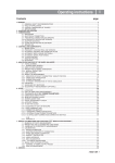
Operating instructions
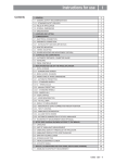
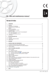
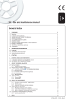
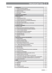
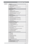
Index
I
1- GENERAL
3
1.1 - GENERAL SAFETY RECOMMENDATIONS
3
1.1.1 - STANDARD SAFETY DEVICES
3
1.2 - FIELD OF APPLICATION
3
1.3 - OVERALL DIMENSIONS
3
1.4 - SPECIFICATION
4
2 - HANDLING AND HOISTING
4
3 - COMMISSIONING
5
3.1 - ANCHORING
5
3.2 - ELECTRICAL CONNECTION
5
3.3 - PNEUMATIC CONNECTION (VERSION P)
5
3.4 - EXTRA SAFETY DEVICES (VERSION P)
5
3.5 - ADAPTER MOUNTING
5
3.6 - GUARD MOUNTING AND ADJUSTMENT
8
3.7 - SPACER WD
8
4 - CONTROLS AND COMPONENTS
9
4.1 - WHEEL LOCKING
9
4.2 - PNEUMATIC LOCKING PEDAL (VERSION P)
9
4.3 - AUTOMATIC DISTANCE AND DIAMETER GAUGE
9
4.3.1 - DISTANCE GAUGE LOCKING
9
4.4 - AUTOMATIC WIDTH GAUGE
9
4.5 - AUTOMATIC WHEEL POSITIONING
9
4.6 - CLOCK CONTROL
9
4.7 - PRINTER (OPTION)
9
4.8 - KEYBOARD
10
5 - INDICATIONS AND USE OF THE WHEEL BALANCER
11
5.1 - INITIAL SCREEN
11
5.1.1 - SCREEN-SAVE SCREEN
11
5.2 - MENU ACCESS DIAGRAM
12
5.3 - PRESETTING WHEEL DIMENSIONS
13
5.3.1 - AUTOMATIC STANDARD WHEEL SETTING
13
5.3.1.1 - AUTOMATIC WIDTH MEASUREMENT
14
5.3.2 - ALUS WHEEL AUTOMATIC PRESETTING
15
5.4 - USER CONTROL
16
5.5.1 - INDICATION OF EXACT CORRECTION WEIGHT POSITION
18
5.5.2 - “SPLIT” CONTROL
19
5.5.3 - CORRECTION MODE
20
5.5.4 - AUTOMATIC MINIMIZATION OF STATIC UNBALANCE
21
5.6 - WHEN AND WHY MATCHING
21
5.6.1 - PRESETTING OF TOLERANCE ON THE MACHINE
22
5.6.2 - VALUE OF STATIC UNBALANCE, CORRELATED WITH ECCENTRICITY
22
5.6.3 - VALUE OF UNBALANCE CORRESPONDING TO ECCENTRICITY
22
5.7 - ECCENTRICITY MEASUREMENT
23
6 - MENU
27
6.1 - OUT OF BALANCE OPTIMIZATION
27
6.2 - DIMENSIONS
27
6.3 - STATISTICS
6.4 - CALIBRATIONS (SEE MENU ACCESS DIAGRAM)
30
6.4.1- GAUGE CALIBRATION
30
6.4.2 - WHEEL BALANCING MACHINE CALIBRATION
30
6.4.3 - VIDEO INTERFACE
30
I 0442 GB - 1
I 0442 GB - 2
6.5 - GENERAL SETUP
31
6.5.1 - LANGUAGE
31
6.5.2 - SCREEN-SAVER
31
6.5.3 - ACOUSTIC SIGNAL
31
6.5.4 -SETTING THE CLOCK
31
6.5.5 - GUARD OPENING DURING SPIN
31
6.5.6 - AUTOMATIC POSITION REPEATER
31
6.5.7.1 - ENABLING WIDTH MEASUREMENT
31
6.5.7.2 - ECCENTRICITY MEASUREMENT
31
6.5.7.3 - ENABLING OF SERIAL OUTPUT RS232C
32
6.5.7.4 - PRINTER ENABLING (OPTIONAL)
32
6.5.7.5 - WHEEL LOCKING ENABLE
32
6.5.7.6 - GAUGE LOCKING ENABLE
32
6.6 - BALANCING SETUP
33
6.6.1 - UNIT OF UNBALANCE MEASUREMENT
33
6.6.2 - UNBALANCE DISPLAY PITCH
33
6.6.3 - TOLERANCE (ALSO SEE CORRECTION METHOD)
33
6.6.4 - RUN WITH GUARD CLOSED
33
6.6.5 - STATIC ALWAYS ENABLED
33
6.6.6 - CORRECTION METHOD
34
6.6.6.1 - STANDARD CORRECTION METHOD
34
6.6.6.2 - EXTERNAL PLANE CORRECTION METHOD
34
6.6.6.3 - IC (INTELLIGENT CORRECTION) CORRECTION METHOD
34
6.7 - SPECIAL FUNCTIONS
35
6.7.1- PRESETTING THE CUSTOMER AND USER NAME
35
6.7.2 - WHEEL BALANCING MACHINE SELF-TEST
35
7 - ERRORS
36
8 - ROUTINE MAINTENANCE
38
8.1 - SCHEDULED MAINTENANCE
38
8.2 - REPLACING FUSES
38
1- General
1.1 - General safety recommendations
- The balancing machine should only be used by duly authorized and trained personnel.
- The balancing machine should not be used for purposes other than those described in the instruction
manual.
- Under no way should the balancing machine be modified except for those modifications made explicitly by
the manufacturer.
- Never remove the safety devices. Any work on the machine should only be carried out by duly authorized
specialist personnel.
- Do not use strong jets of compressed air for cleaning.
- Use alcohol to clean plastic panels or shelves (AVOID LIQUIDS CONTAINING SOLVENTS).
- Before starting the wheel balancing cycle, make sure that the wheel is securely locked on the adapter.
- The machine operator should not wear clothes with flapping edges. Make sure that unauthorized personnel
do not approach the balancing machine during the work cycle.
- Avoid placing counterweights or other objects in the base which could impair the correct operation of the
balancing machine.
1.1.1 - Standard safety devices
- STOP push button for stopping the wheel under emergency conditions.
- The safety guard of high impact plastic is with shape and size designed to prevent risk of counterweights
from flying out in any direction except towards the floor.
- A microswitch prevents starting the machine if the guard is not lowered and stops the wheel whenever the
guard is raised.
1.2 - Field of application
The machine is designed for balancing car or motorcycle wheels weighing less than 75 kg. It can be operated within a
temperature range of 0° to +45°C.
It can measure the geometric radial run-out of the wheels (optional).
It can print a balancing certificate (option).
1.3 - Overall dimensions
868
1277
1992
1
I 0442 GB - 3
1.4 - Specification
Single phase power supply...............................................................115 - 230 V 50-60 Hz
Protection class ...............................................................................IP 54
Max. power consumption..................................................................1,1 Kw
Monitor .............................................................................................TFT 15”
Balancing speed ...............................................................................180 min-1
Cycle time for average wheel (14 Kg) .............................................6 seconds
Balancing accuracy ..........................................................................1 g
Position resolution ............................................................................± 1.4 °
Average noise level ..........................................................................< 70 dB(A)
Distance rim - machine .....................................................................0 - 285 mm (400 mm can be preset)
Rim width setting range ..................................................................1.5” ÷ 20” or 40 ÷ 510 mm
Diameter setting range .....................................................................10” ÷ 30” or 265 ÷ 765 mm
Total wheel diameter within guard ....................................................1067 mm (42")
Total wheel width within guard ..........................................................500 mm
Min/max. compressed air pressure ..................................................7 ÷ 10 Kg/cm2
..........................................................................................................approx. 0.7 to 1 Mpa;
..........................................................................................................approx. 7 to 10 BAR;
..........................................................................................................approx. 100 to 145 PSI.
2 - Handling and hoisting
N.B. DO NOT HOIST THE MACHINE BY LEVERING UNDER THE CABINET.
2
I 0442 GB - 4
3
3 - Commissioning
3.1 - Anchoring
The machine can be operated on any flat non-resilient floor.
Make sure that the machine rests solely on the three support points provided (fig. 3).
If possible, it is advisable to anchor to the floor using relative mounting feet in the event of continual use with wheels
weighing over 35 Kg.
3.2 - Electrical connection
The machine is supplied with a single phase mains cable plus earth (ground).
The supply voltage (and mains frequency) is given on the machine nameplate. It may NOT be changed.
Connection to the mains should always be made by expert personnel.
The machine should not be started up without proper earth (ground) connection.
Connection to the mains should be through a slow acting safety switch rated at 4A amp (230V) or 10 amp (115V) .
3.3 - Pneumatic connection (version P)
For operation of the spindle with pneumatic locking (constant thrust air spring) connect the balancing machine to the compressed air main. The connection fitting is located at the back of the machine. A pressure of at least 7 kg/cm2 (approx. 0.7
MPa or 7 BAR or 100 PSI) is required for correction operation of the release device.
3.4 - Extra safety devices (version P)
- Wheel always locked even when there is pressure failure during the balancing cycle.
- Always actuate the unlocking control pedal with the machine stationary in order to avoid stress and
abnormal wear on the adapter.
3.5 - Adapter mounting
The balancing machine is supplied complete with cone adapter for fastening wheels with central bore. Other optional
flanges can be mounted once the terminal part is removed (also see enclosed brochures)
N.B.: Carefully clean the coupling surfaces before performing any operation.
DISMOUNTING THREADED END PIECE
4
A
B
a) Back-off screw B and remove threaded end-piece A.
b) Fit the new adapter.
I 0442 GB - 5
SE2-Mounting
0m
m
B
A
1-2
mm
C
D
E
F
G
SE2_ 0140
SE2-Dismounting
36
0°
A
B
C
D
Cone
E
- Quando possibile, centrare le ruote con cono dall'interno (vedi disegno).
- Evitare di usare il manicotto RL con cerchi di ferro.
- Whenever possible, centre the wheels with the cone from the inside (see the drawing).
- Avoid using the RL sleeve with metal rims.
- Lorsque c’est possible, centrer les roues avec le cône de l’intérieur (voir dessin).
- Eviter d’utiliser le manchon RL avec les jantes en fer.
- Wenn möglich, die Räder mit Konus von Innen heraus zentrieren (siehe Zeichnung).
- Bei Eisenfelgen die Verwendung der Muffe RL vermeiden.
- Siempre que sea posible, centrar las ruedas con cono desde dentro (véase dibujo).
- Evitar usar el manguito RL con llantas de hierro.
- Quando possível, centre as rodas com cone pelo lado de dentro (ver figura).
- Evite utilizar a luva RL com jantes de ferro.
SE2_ 0140
3.6 - Guard mounting and adjustment
a) Fasten the components to the base as illustrated in specific exploded view.
b) The position of the wheel guard when closed can be adjusted with relative screw accessible at the back. Correct
position is shown in Fig. 1.
c) With the guard closed check that the microswitch prod has slipped into place on the ring.
d) Appropriately adjust the angular position of the control ring.
3.7 - Spacer WD
When balancing very wide wheels (9”), there is not enough space to turn the distance gauge. To withdraw the wheel
from the machine side, fit spacer WD on the adapter body and secure it with the standard issue nuts. When centring the
wheel with the cone on the inside, fit the spacer DC to obtain spring thrust.
5
DC
Spring
I 0442 GB - 8
WD
Cone
4 - Controls and components
4.1 - Wheel locking
The wheel is automatically locked when reaching the correct angular position for weight application on the inside and
outside, turning it slowly by hand. To unlock the wheel, turn it hard to move it from the correct correction position.
Pressing the
button the chuck can be locked/released in any position to facilitate mounting the wheel.
4.2 - Pneumatic locking pedal (version P)
6
This pedal allows releasing the device fastening the
wheel on the adapter. Do not actuate this pedal
during the machine cycle and/or when adapters
other than the standard cone adapter are mounted.
The pedal has two stable positions: top, wheel unclamped; bottom, wheel clamped.
4.3 - Automatic distance and diameter gauge
This gauge allows measurement of the distance of the wheel from the machine and the wheel diameter at the point of
application of the counterweight.
It also allows correct positioning of the counterweights on the inside rim by using the specific function (see INDICATION OF EXACT CORRECTION WEIGHT POSITION ) which allows reading, on the monitor, the position used for the
measurement within the rim (For calibration, see CALIBRATION). The gauge can be used only with the weight clip
mounted.
4.3.1 - Distance gauge locking
The distance gauge is automatically locked when the adhesive weights have reached the correct application
distance. To release the gauge, lower it to below 10” diameter.
4.4 - Automatic width gauge
Width gauging is through a SONAR device which measures the distance of the wheel without mechanical contact,
merely by closing the guard and each time a valid measurement has been made with AUTOMATIC DISTANCE AND
DIAMETER GAUGE.
4.5 - Automatic wheel positioning
At the end of the run, the wheel is positioned in relation to external or static out-of-balance (when selected).
Accuracy is +/-20 degrees for wheels weighing up to 25 kg.
4.6 - Clock control
The wheel balancing machine is provided with a clock having a back-up of about one month with the machine
switched off. If the machine remains unused for a long period, check date and time settings when restarting (see
CLOCK SET-UP).
4.7 - Printer (option)
Used to print useful information for the vehicle, residual imbalance and eccentricity for the balanced tyre.
I 0442 GB - 9
4.8 - Keyboard
FUNCTION KEYS: they immediately select the function on screen
7
Selection of special
function
N.B.
Confirm
Starts measuring
cycle
Stops machine
cycle
- Press the buttons with the fingers only: never use the counterweight pincers or other pointed objects.
- When the beep signal is enabled (see section ACOUSTIC SIGNAL), pressing of any push button is
accompanied by a “beep”.
I 0442 GB - 10
5 - Indications and use of the wheel balancer
The monitor shows several information and suggests various alternative ways of use to the operator.
This is through various “screens”.
5.1 - Initial screen
Buttons enabled
: main functions screen (see MENU ACCESS DIAGRAM)
: static correction (see CORRECTION MODES)
: balancing spin (see RESULT OF MEASUREMENT )
Dimensions gauge: when extracted, the Dimensions screen is selected (see PRESETTING OF WHEEL DIMENSIONS) .
If the machine remains on the initial screen for a certain amount of time without being used, the system is automatically switched to a screen-save. Striking of any key, movement of the wheel of distance + diameter gauge will cause
automatic switching from the screen-save menu to the initial screen. Automatic start-up operated by the protection
system is not available from the screen-saver for safety reasons.
5.1.1 - Screen-save screen
N.B.: Name of the wheel balancer’s owner. Can be preset via the monitor (see Section CALIBRATIONS).
FOCUS srl
23826 MANDELLO DEL LARIO (LC) Italy
Via Petrarca, 11 - Tel. (+39) 0341 701081
I 0442 GB - 11
5.2 - Menu access diagram
N.B. :
- The symbol ”
“ indicates the presence of a further menu:
- To return to the previous menu, press button
- To return to the initial screen, press button
PASSWORD :
+
+
FOR SPECIALIZED PERSONNEL ONLY
I 0442 GB - 12
+
5.3 - Presetting wheel dimensions
5.3.1 - Automatic standard wheel setting
LT FUNCTION ON
INDICATOR
(see enabled buttons)
FUNCTION ON
INDICATOR: Sonar
“WIDTH”.
The screen appears upon removing the distance + diameter gauge.
The “dimension acquired” message is indicated by the correction weight symbol, which changes from blue to red.
- Standard wheels: Using the special grip, move the end of the gauge against the rim in one of the positions A/B
shown in fig. 8.
a) Sprung weight : in one of the positions A/B indicated in figure 8.
Pos A
8
b) Adhesive weight: in the position indicated below.
Pos B
8a
Position of adhesive
weight
FI
Note: Always use the round part of the striker plate.
- Hold the gauge in position for at least 2 seconds.
If the acoustic signal is enabled (see ACOUSTIC SIGNAL), the acquisition of the dimensions is accompanied by a
“beep”.
I 0442 GB - 13
Set the distance+diameter gauge to the rest position:
the current width value is displayed inside the tyre.
- Set the nominal width, which is normally shown on the rim, or measure the width “b” with the
caliper gauge provided.
b
The other enabled buttons are:
See USER control
Select the type of weight to apply (see CORRECTION METHODS).
Return to initial frame.
Balancing spin.
5.3.1.1 - Automatic width measurement
Gradually lower the guard after carrying out measurement of distance + diameter in automatic mode.
If the width measured is incorrect (out of range), the following message appears:
“Sonar measure is out of range:”
“F1 = repeat”
“F2 = manual set-up”
Press F1 to re-lower the guard and repeat the width measurement. Press F2 to go to the dimensions panel for
manual insertion of the width measurement. Manually presetting is possible by using the push buttons as described in
"DIMENSIONS".
I 0442 GB - 14
5.3.2 - ALUS wheel automatic presetting
After the measurement performed for the FI inner side, as indicated in fig. 9, pull out the gauge again to store the
data for the FE outer side; choose position A or B (fig. 8) at your choice. Keep this position for at least 2 seconds.
The counterweight symbols change colour.
When the acoustic signal is enabled (see ACOUSTIC SIGNAL), the acquisition is accompanied by a “beep”.
9
FI
FE
Position of
adhesive
weights
After having detected the dimensions, use the
side.
key to indicate the type of correction selected for the inner
The buttons enabled in the case of:
1) automatic width measurement
2) automatic ALUS wheel measurement
are:
See USER control
Selection of clip or adhesive weight for inside.
Only for automatic width:
The key L.T. (LIGHT TRUCK) used to improve the dimensional calibration of large-diameter
wheels such as off-road, trucks, wheels which protrude significantly from the rim. Press the
key L.T. several times to select the type of tyre projection (from 1.0” to 2.0”). The option is
disengaged at the end of current Width Measurement.
Selecting the manual dimension presetting screen
Return to initial screen.
Balancing run.
N.B.:
The ALUS dimensions can in any case be set manually using the buttons described in
“DIMENSIONS”.
I 0442 GB - 15
5.4 - USER control
Selected by pressing
from the automatic setting frame for standard wheels, (see PRESETTING WHEEL DIMEN-
SIONS).
The wheel balancing machine can be used simultaneously by 4 different users who, through a simple sequence, can
memorize their work condition and call it when needed. The names of the users can be stored (PRESETTING CLIENT
AND USER NAMES).
Selecting the user to call up and program
Recalling the selected user
The system automatically returns to the initial screen with recalculation of the unbalance values
on the basis of the effective dimensions of the USER called.
NOTE : - The dimensions memorized as USER are lost when the machine is switched off;
- The current USER is always displayed in the Measurements and Dimensions screens.
Programming the selected user
Remember to set correctly the dimensions in the manner already decribed in the paragraph
“PRESETTING OF WHEEL DIMENSIONS”.
I 0442 GB - 16
5.5 - Measurement result
After performing a balancing run, the out-of-balance values are displayed as well as arrows useful for positioning the
correction weight at the application point. After positioning and locking the wheel, apply the weight vertically at the
top. When the beep signal is enabled (see section ACOUSTIC SIGNAL), reaching of the correction position is
accompanied by a “beep”.
If the out-of-balance is less than the chosen threshold value, “0K” appears instead of the out-of-balance value to
indicate, on that particular side, that the wheel is in tolerance; the residual out-of-balance can be displayed by
pressing the button
, with an accuracy of 0.5 g (0.1 oz.)
The following buttons are enabled:
Display of residual out-of-balance.
Selection of correction mode (STATIC/DUAL SURFACE). When the mode is changed, the
unbalance values are recalculated automatically on the basis of the previous spin.
Simultaneous display of the dynamic+static unbalance can be enabled through the special
function in Setup, (see par. STATIC ALWAYS ENABLED).
Prints the balancing certificate (option)
: Eccentricity measurement graph (OPTIONAL).
N.B : 1. The symbol above the key is displayed in yellow if the first harmonic eccentricity exceeds the limit set in the setup parameters (FIRST
HARMONIC LIMIT).
2. When this push button is held down for more than 1.5 seconds, eccentricity measurement is temporarily disenabled (enabled in
GENERAL SETUP). To re-enable eccentricity measurement, press push button [4] again for more than 1.5 seconds. Every time the
machine is switched on, the status of eccentricity measurement reflects the settings in GENERAL SETUP.
Unbalance split function enable
Enable indication of the longitudinal position of the out-of-balance (INDICATION OF EXACT CORRECTION
WEIGHT POSITION).
When “AUT” appears above this button, it means that
does not have to be pressed to access
the position repeater function; the distance+diameter gauge can simply be pulled out.
Selection of special functions
Balancing run.
N.B.:
If the machine remains on this screen without being used for more than the time preset in the Setup
parameters (6), the screen automatically returns to the screen-saver.
I 0442 GB - 17
5.5.1 - Indication of exact correction weight position
It is recommended always to use this function when correcting the out-of-balance with adhesive weights ALUS.
Remember to thoroughly clean the application areas.
In all cases this function allows cancelling approximations in the mounting of counterweights with consequent reduction of the residual unbalance.
From the measurement results frame:
A) Position the wheel when applying the weight.
- Press button
.
- Extract the gauge in position A, figure 8.
B) A mobile coloured arrow [
C) When a fixed arrow [
] indicates the approach of the weight towards the correction position.
] is reached, rotate the wheel to correction position (FI or FE) and apply the
counterweight by rotating the gauge tip towards the outside, into the position where the pincer touches the wheel
(where appropriate use the weight pusher).
D) The correction weight application position is automatically reset in relation to the position of the distance +
diameter gauge (Pos. A, Fig.8).
When the acoustic signal is enabled (see ACOUSTIC SIGNAL), attainment of the fixed arrow status [
] is
accompanied by a “beep”.
If gauge locking is enabled (see GAUGE LOCKING), when a fixed arrow [
] is reached, the gauge is automatically
locked to prevent shifts during application of the correction weight. To release and bring the gauge back to the rest
position, lower it to below 10” diameter.
10
FI
I 0442 GB - 18
FE
5.5.2 - “SPLIT” control
SPLIT is only possible in the event of static unbalance or ALUS external side and is used to hide any adhesive
weights correcting unbalance behind the rim spokes.
To split the unbalance detected in two different positions, proceed as follows :
1. Position static unbalance or ALUS external side in the correction position :
2. Select a spoke close to the 12 o’clock postion to be corrected, more it into the 12 o’clock position and press button
[6].
3. Turn the wheel in the rotation direction indicated on the unbalance display, brining the second spoke to the 12
o’clock position and press button [6].
- Turn the wheel in direction of rotation.
- Turn the wheel in reverse direction of rotation.
4.
5.
At this point, two indications appear on screen for positioning of the unbalance correction spokes.
Position the spokes indicated on screen in the 12 o’clock position and correct with the value displayed.
Any error in this procedure is clearly shown on screen.
Always follow the information provided by the wheel to optimise correction.
I 0442 GB - 19
5.5.3 - Correction mode
After having performed automatic measurement of the inner side, it is possible to place the correction weights as
required by pressing pushbuttons
N.B.:
,
and
.
In the event of automatic measurement of both sides, if the difference between the inner and
outer diameters is greater than or equal to 2”, the system sets the inner side spring weight. To
modify this presetting, press the
To display static unbalance, press the
diameter is always considered).
button. The external side may only be “adhesive”.
button on the measurement screen (for ALUM static, the inner side
Possible types of correction:
11
Balancing of steel or light alloy rims with application of clip-on
weights on the rim edges
The STATIC mode is necessary for motorcycle wheels or when it is
not possible to place the counterweights on both sides of the rim.
Balancing of light alloy rims with application of adhesive weights on
the rim shoulders.
Combined balancing: adhesive weight on the outside, clip-on weight
inside.
Combined balancing: clip-on weight outside and adhesive weight inside.
ALU
ALU
S S:
Balancing of alloy rims with hidden application of the adhesive
weight on the outside.
Combined balancing: clip-on weight inside and adhesive hiddenweight outside
(Mercedes).
I 0442 GB - 20
5.5.4 - Automatic minimization of static unbalance
Initial unbalance
sx
dx
g
g
phase shift
5 0°
Possible approximations
sx
sx
dx
g
residual static 4
g
g
sx
dx
g
g
residual static 3 g
sx
dx
g
g
residual static1
g
dx
g
g
6g
residual static
With conventional
Choice with minimum
wheel balancer
static residual
This program is designed to improve the quality of
balancing without any mental effort or loss of time by
the operator. In fact by using the normal commercially
available weights, with pitch of 5 in every 5 g, and by
applying the two counterweights which a conventional
wheel balancer rounds to the nearest value, there
could be a residual static unbalance of up to 4 g.
The damage of such approximation is emphasized
by the fact that static unbalance is cause of most
of disturbances on the vehicle. This new function,
resident in the machine, automatically indicates
the optimum entity of the weights to be applied by
approximating them in an “intelligent” way according
to their position in order to minimize residual static
unbalance.
5.6 - When and why MATCHING
The software associated with eccentricity measurement is a powerful tool for determining the need to perform relative
rotation between the rim and tyre in order to reduce the eccentricity of the wheel down to acceptable limits. The
principle adopted is based on the consideration that a rim with acceptable tolerance, mounted with an acceptable
tyre, can statistically generate a total eccentricity which is not acceptable but can be improved by matching.
Generally speaking, rim measurement is not necessary, accurate or useful because:
• To measure the rim it is necessary to remove the tyre. There can by coarse errors on the outside (e.g. aluminium
wheels!)
• The two rim sides can be eccentric in a very different way. Therefore to which one to make reference? What is the
effect on the tyre mounted?
• To improve the eccentricity of a wheel, the rim should be eccentric, to compensate the tyre. And viceversa.
• If after a rotation by 180° of a wheel, the value is still out-of-tolerance, either the tyre or rim are too eccentric: one
of the two must be replaced!
wheel
Ideal wheel
rim
Example 1
Rim + 0.8 mm
Tyre + 0.6 mm
tyre
Wheel + 1.3 mm
rotation axle
SOLUTION:
Rotate the tyre on the rim by 180°
Eccentricity of the wheel is
excessive, due to an acceptable
rim or tyre but randomly placed in an
“unfortunate” relative position.
RESULT:
wheel eccentricity 0.3 - 0.4 mm
(in tolerance)
I 0442 GB - 21
wheel
Ideal wheel
Example 2
rim
Rim + 0.8 mm
Tyre - 0.6 mm
Wheel + 0.3 mm
tyre
Eccentricity of the single items has
been compensated.
The wheel is acceptable.
rotation axle
wheel
Ideal wheel
Example 3
rim
Rim 0 mm
Tyre + 1.2 mm
Wheel + 1,2 mm
tyre
Eccentricity of the wheel cannot be
compensated by the rotation because
the rim is perfect!
rotation axle
SOLUTION:
Rotate the tyre on the rim by 180°
RESULT:
no improvement is obtained
5.6.1 - Presetting of tolerance on the machine
There is no general rule concerning acceptability of an eccentricity value . As a first approximation we consider it correct to use a threshold of 1 to 1.5 mm. The E/ECE/324 standard prescribes 1.5 mm as max. eccentricity of a rebuilt
tyre.
5.6.2 - Value of static unbalance, correlated with eccentricity
Clear indication is given in the Measurement screen of both the value and position of the static unbalance as well
as the eccentricity. In fact, it is interesting to check the correlations of the two values, above all of the two positions.
When the two positions have a similar angle (± 30° one from the other), there is a clear sign that an eccentricity is
present which can be compensated by matching.
5.6.3 - Value of unbalance corresponding to eccentricity
For user’s reference, the centrifugal force is calculated corresponding to a certain speed, compared to the force
generated by the eccentricity present on the tyre (calculated with an approximate average elastic constant).
I 0442 GB - 22
5.7 - Eccentricity measurement
The much enlarged figures show the outer tyre surface and axis of wheel rotation.
Fig. A - shows measurement of the total Peak-to-Peak eccentricity defined as maximum radial deviation of the tyre
surface.
Fig. B - shows measurement of the eccentricity of the 1st
harmonic, i.e. the eccentricity of that circle which “recopies”
the tyre shape, by averaging the local deviations of the
tyre from the round shape.
A
B
Obviously the P.P. measurement is normally greater than
that of the 1st harmonic. Tyre manufacturers normally
supply two different tolerances for the two eccentricities.
The radial and lateral eccentricity measurements are automatically carried out after the unbalance measurement
without having to go into particular procedures. Remember to position the sonar sensors in front of the surface to be
measured before pressing the
button.
The maximum limit of the first harmonic can be set (see FIRST HARMONIC LIMIT ). When this limit is exceeded,
the wheel balancer displays a warning and diagnostic frame indicating an eccentricity condition that needs to be
corrected.
The following buttons are enabled:
to display the graphs of the eccentricity measured
to go to the unbalance display frame (the symbol above the button
yellow to indicate an excessive first harmonic eccentricity value).
is displayed in
I 0442 GB - 23
If the first harmonic eccentricity is within the permitted limit, the graphs can in any case be displayed
by pressing the button
from the unbalance measurement frame:
-
radial eccentricity measurement graph:
-
radial and lateral eccentricity measurement graph
BLUE GRAPH:
RED GRAPH:
represents the peak/peak eccentricity whose actual value is displayed and updated by
turning the wheel in correspondence to the word “Cursor”.
represents the first harmonic eccentricity. For a wheel in optimal conditions, this
graph must come close to a straight line.
The following buttons are enabled:
to go to rim eccentricity measurement
to print the eccentricity values measured (option)
to go to a frame where important information on eccentricity is displayed, among which the unbalancing
effect the first harmonic eccentricity measured at an average speed of 120 km/h may have.
to return to the unbalance measurement frame
I 0442 GB - 24
30 mm
SONAR LR INSTRUCTION
8°
FRONT VIEW
LATERAL VIEW
In order to obtain the correct lateral eccentricity values, the sonar cone must be positioned inside the tyre shoulder.
The function of the LED is to make it easier to position the sonar correctly, but always bear in mind that it does not
indicate the focus of the pad as it is situated 30 mm further down.
The rim eccentricity measurement is important in order to try and reduce the total eccentricity of the wheel simply by
turning the tyre on the rim.
- Press the button
from the eccentricity graph display frame
- Hold the gripper as shown in Photo A in such a way that it does not turn during the measurement
- Rest the round part of the gripper inside the rim as shown in Photo B.
A
B
- Press the
button and slowly turn the wheel by hand, keeping a constant pressure on the gripper until the
following frame appears:
I 0442 GB - 25
The graph simultaneously shows the total eccentricity, the rim and the tyre values. Before turning the tyre on the rim,
check if the POSSIBLE REDUCTION indicated on-screen is sufficient to bring the wheel eccentricity within tolerance.
It is possible to set the minimum correction limit below which it is never considered appropriate to intervene (see
MINIMUM CORRECTION LIMIT ), and the maximum first harmonic eccentricity limit of the rim below which it is considered of little use to turn the tyre on the rim (see FIRST HARMONIC LIMIT ).
The following buttons are enabled:
prints the eccentricity values measured (option)
returns to the eccentricity graph display frame.
I 0442 GB - 26
6 - Menu
6.1 - Out of balance optimization
The symbol
is displayed automatically for static out-of-balance exceeding 30 grams (1.1oz).
The program allows total wheel out-of-balance to be reduced by compensating, when possible, tyre and rim out-ofbalance values. It requires two runs, rotating the tyre on the rim on the second run. Having performed a run,
press
+
and follow the on-screen instructions.
6.2 - Dimensions
If necessary, the dimensions can be input or edited in manual mode as follows:
- press
+
or else press
or from the automatic dimension setting screen (which can be
reached by pulling out the distance + diameter gauge);
- press
to select the dimension to be preset (red);
- press
/
- press
press to change unit of measurement.
to preset the required value;
I 0442 GB - 27
Dimension definition for corrections with clip-on weights:
d = DIAMETER:
preset the nominal diameter stamped on the rim.
b = WIDTH:
Preset the nominal width which is normally stamped on the rim (see AUTOMATIC STANDARD
WHEEL SETTING)
a = DISTANCE:
set the distance of the internal side of the wheel from the machine, measuring it as described in
fig. 12.
12
b
Pos. 0
(First notch)
a
d
- INNER ADHESIVE WEIGHTS (ALU S)
Even in correction mode with adhesive weights, the dimensions can be input or modified manually using the buttons
shown on screen in accordance with the technical data displayed.
For a better understanding of the screen contents, refer to the following outline:
13
14 mm
Pos. 0
(First notch)
N.B.:
aI
aE
Correct manual setting of ALU S envisages aE > aI + 1.5”.
If this condition is not observed:
- an error message is displayed at the top of the screen;
- exit from the ALU S manual panel is disenabled until correct aI/aE values are set.
I 0442 GB - 28
6.3 - Statistics
DAILY N° OF RUNS:
Indicates the number of runs performed as from switching on the machine.
Such parameter is automatically reset after switching the machine off.
TOTAL N° OF RUNS:
Indicates the number of runs starting from the date indicated in square brackets.
This parameter remains memorized even when the machine is switched off.
DAILY WEIGHT SAVED
Indicates the weight saved when using the IC instead of the standard correction method from the moment the wheel
balancer is turned on. This parameter is automatically reset after turning off the machine.
TOTAL WEIGHT SAVED
Indicates the weight saved when using the IC instead of the standard correction method from the date indicated in
square brackets. This parameter remains memorized even when the machine is switched off.
The following buttons are enabled:
: Press to reset the relative counter.
For the TOTAL counters a correct password must be entered.
: Prints some statistical values (optional)
: To return to the previous screen.
I 0442 GB - 29
6.4 - Calibrations (see MENU ACCESS DIAGRAM)
To access “Calibrations and reserved functions”, a password must be given.
Any incorrect operation within the functions described below could impair the peration of the wheel
balancing machine. Unauthorized use will cause cancellation of the machine warranty.
6.4.1- Gauge calibration
Select the gauge to be calibrated and follow the on-screen instructions.
N.B.:
- In width gauge calibration, the dimension needs to be set:
A-
GAUGE “ZERO” DISTANCE
SONAR “ZERO” DISTANCE
14
0 gauge
0 (Zero
calibro)
DISTANCE
DISTANZA
(First notch)
6.4.2 - Wheel balancing machine calibration
For machine calibration, proceed as follows:
- Mount an average size wheel with steel rim. Es.: 6” x 14” (± 1”)
- Preset the wheel dimensions with GREAT CARE.
- Follow the on-screen instructions.
6.4.3 - Video interface
Select based on the monitor used
Incorrect selection results in the images being displayed in very dark colours.
I 0442 GB - 30
6.5 - General setup
(See Menu access diagram)
The Setup screen provides the user with many possibilities required for presetting the machine in relation to his own
requirements. Such settings remain unaltered even when the machine is switched off.
The following buttons are enabled:
: return to previous window
: return to measurement screen
from
to
: for parameter selection.
6.5.1 - Language
This function allows selection of the language to be used for displaying descriptive and diagnostic messages
regarding machine operation.
6.5.2 - Screen-saver
If enabled (ON), if the machine is left unused on the initial frame, the screen saver automatically comes on.
The function can be disabled by setting “OFF”.
6.5.3 - Acoustic signal
When “ON” is selected, the acoustic signal (beep) is enabled in the following cases:
- when any push button is pressed;
- when dimensions are acquired in automatic mode;
- when the correct angular position for weight application is reached in the Measurement screen;
- when the correct angular position for weight application is reached in the position repeater screen.
6.5.4 -Setting the clock
Used to set date and time correctly. Follow the instructions on the screen.
6.5.5 - Guard opening during spin
Selecting “ON” the option to open the guard (when the motor is off) during the spin is enabled. If the guard is opened
when the motor is on, error 5 (guard open) is displayed.
Selecting “OFF”, error 5 (guard open) will always be signalled when the guard is opened.
6.5.6 - Automatic position repeater
When selecting “ON”, the option to automatically access the position repeater function is enabled by pulling out the
distance+diameter gauge after having done a balancing spin and going to the correction position.
In the measuring panel, the option to use the automatic position repeater is shown on the display and “AUT” appears
near the Position Rep. [F7] button.
6.5.7 - Options
6.5.7.1 - Enabling width measurement
This function enables/disenables automatic width measurement with SONAR device.
6.5.7.2 - Eccentricity measurement
Enables display of a menu where the following parameters can be set:
▪ Side eccentricity measurement enable: Enables/disenables lateral eccentricity measurement.
▪ Radial eccentricity measurement enable: Enables/disenables radial eccentricity measurement.
▪ Eccentricity diagnostics enable: Enable/disenables eccentricity diagnosis.
▪ Eccentricity unit of measure: It is possible to select display of eccentricity measurements in mm or inches.
▪ First harmonic limit: The first harmonic limit beyond which it is felt suitable to rotate the tyre on the 180° rim.
Recommended Limit = 1.2 mm.
▪ Rim first harmonic limit: Represents the first harmonic limit of the rim below which it is not considered appropriate
to turn the tyre on the rim. Recommended limit: 0.3 mm.
▪ Minimum correction limit: Represents the minimum correction limit obtainable below which it is not considered
appropriate to turn the tyre on the rim. Recommended limit: 0.8 mm.
I 0442 GB - 31
6.5.7.3 - Enabling of serial output RS232C
This option enables/disables the sending of the measured unbalance and phase values to serial output RS232C.
Transmission speed
= 9600 baud
Data format
= 1 bit Start
8 bit Data
Parity NONE
1 bit Stop
At the end of each unbalancing measuring spin, the balancing machine transmitt all information concerning the unbalance
measured. The items of data transmitted via serial line are in ASCII format and are separated between each other by
the <cr> character (0x0d).
Sending sequence is as follows:
- 00000 <cr>
- Value of correction weight, left side <cr>
- Correction phase, left side <cr>
- Value of correction weight, right side <cr>
- Correction phase, right side <cr>
The first 5 zero bytes represents the start of transmission message. The correction values are expressed in grams, in
steps of .1 gram.
The phase values are expressed in degrees, in the range 0 ÷ 359.
6.5.7.4 - Printer enabling (optional)
Enable/disable printer and relative print options.
N.B.: If the options RS232 serial port and printer are enabled at the same time, both will malfunction.
6.5.7.5 - Wheel locking enable
Enables/disables wheel locking in the correction position (see WHEEL LOCKING). The possible options are:
OFF: Disabled
ON: enabled
ALUS : Enables wheel locking in position for the ALUS correction mode only.
Wheel locking by means of the button
is enabled for the ON/ALUS modes.
6.5.7.6 - Gauge locking enable
Enables/disables distance gauge locking when the correct distance has been reached to apply the adhesive weight to
correct the unbalance.
To release the gauge, lower it to below 10” diameter.
I 0442 GB - 32
6.6 - Balancing setup
6.6.1 - Unit of unbalance measurement
It is possible to select whether to display the unbalance values expressed in grams or ounces.
6.6.2 - Unbalance display pitch
This represents the unbalance display pitch and varies in relation to the unit of measurement selected. The selection
“5 g” (1/4 oz) enables display of the correction values on both sides such as to bring the static unbalance to 0 (theoretical). It is recommended to preset this function as standard on the machine as it improves the balancing
quality. The computer makes a complex calculation which allows cancelling the residual static unbalance by
varying the value and position of the counterweights fixed in steps of 5 grams (1/4 oz).
6.6.3 - Tolerance (also see CORRECTION METHOD)
This is the unbalance threshold below which the word “OK” instead of the unbalance value appears on the screen at
the end of the spin:
The tolerance varies based on the correction method selected.
In the case of IC (Intelligent Correction), set the static tolerance limit and the average weight of a reference wheel of
6” in width and 15” in diameter.
The following buttons are enabled:
parameter selection during setting
parameter decrease/increase during setting
default parameter setting recommended by the manufacturer
return to previous frame.
6.6.4 - Run with guard closed
When “ON” is selected, automatic run start is enabled when the guard is closed.
6.6.5 - Static always enabled
Simultaneous display of the selected correction plane unbalance as well as STATIC unbalance can be enabled/disa
bled. The static frame can always be selected by pressing the button
from the measuring frame.
I 0442 GB - 33
6.6.6 - Correction method
One of the three possible correction methods can be selected based on the specific requirements of the customer.
6.6.6.1 - Standard correction method
The wheel balancer considers the unbalance within tolerance when the value of each single plane is lower than the
tolerance set.
6.6.6.2 - External plane correction method
If correcting with adhesive weights, the unbalance is considered within tolerance when the recalculated external
plane weight (clip-on weights) is lower than the tolerance set.
Additional windows appear on the screen always displaying the residual external plane value (clip-on weight):
6.6.6.3 - IC (intelligent correction) correction method
The correction plane unbalance is considered within tolerance when both the STATIC and the DYNAMIC TORQUE
unbalances are lower than the tolerance set.
This correction method allows considerably reducing the weight to be applied, yet maintaining excellent balancing
quality. An icon appears on the screen showing the value of weight saved with respect to standard balancing.
If a special icon appears near the button
, it means that the wheel balancer is suggesting static balancing,
however, such that also the dynamic torque unbalance will be brought within tolerance.
When pressing the button
should be positioned in the rim.
I 0442 GB - 34
, the position repeater frame is accessed which clearly indicates where the weight
NOTE: The innovative IC software has been designed to reduce the amount of weight used to correct the
unbalance, leaving a residual unbalance on the wheel within the set tolerances.
The tolerance used by the machine is obtained from a tolerance of a reference wheel, modified in order to
make the vibration generated by the reference wheel comparable with that in use.
This is obtained according to the coded theory of the ISO standards.
In general, a wheel balanced using IC has a higher residual unbalance than a wheel balanced at best using
the conventional method, but, although generating a tolerable vibration from the vehicle, it has the
advantage of considerably reducing the counterweights used.
6.7 - Special functions
6.7.1- Presetting the customer and user name
The machine can be customized by presetting:
a) The name appearing on the initial screen (screen-saver).
b) The name of 4 different machine users ( USER NAME).
6.7.2 - Wheel balancing machine self-test
An automatic self-diagnostic cycle is provided for easier trouble-shooting. At the end of the self-diagnostic cycle,
several parameters are displayed which are useful for the Technical Service Department in order to identify machine
faults.
Enables a special encoder test function reserved for specialised personnel.
Returns to previous menu
CHECKING THE ENCODER
When the spindle is rotated:
- the angular position “POS” should vary from 0 to 255;
- the wording “UP” should appear when rotated clockwise and “DOWN” when rotated in the opposite direction.
Check for correct operation
of the diameter gauge;
the number increases
when the gauge is rotated
outwards.
Encoder check
Check for correct operation of the distance gauge;
the number increases
when the gauge is pulled
out.
Check of the side eccentricity sonar: the number
decreases when a surface
is approached to the
sonar.
Check of the width sonar:
the number decreases when a surface is approached to the sonar.
Check of the radial eccentricity sonar: the number
decreases when a surface is approached to the
sonar.
The values read by sonars 1 and 3 can be displayed one at a time; select the sonar to be tested by pressing
.
In the event of failure or faulty operation of the wheel balancing machine, notify the Technical Service of all the
parameters displayed.
I 0442 GB - 35
7 - Errors
ERRORS CAUSES
CONTROLS
Black
The wheel balancer does not switch on.
1.
2.
3.
4.
Verify correct connection to the mains.
Verify and eventually replace the fuses on the power card.
Verify monitor function.
Replace the computer board.
Err. 1
No rotation signal.
1.
2.
Verify belt tautness.
Verify the function of the phase pick-up board and, in particular,
the reset signal.
Replace the phase pick-up board.
Replace the computer board.
3.
4.
Err. 2
Speed too low during detection.
During unbalance measurement rotation,
wheel speed is less than 42 rpm.
1.
2.
3.
Err. 3
Unbalance too high.
1.
2.
3.
4.
Err. 4
Rotation in opposite direction.
After pressing [START], the wheel begins
to rotate in the opposite direction (anticlockwise).
1.
Verify the connection of the UP/DOWN – RESET signals on the
phase pick-up board.
Err. 5
Guard open
The [START] pushbutton was pressed
without first closing the guard.
1.
2.
3.
4.
Reset the error by pressing pushbutton [7]=End.
Close the guard.
Verify the function of the protection uSwitch.
Press the [START] pushbutton.
Err. 7 /
Err. 8
NOVRAM parameter read error
1.
2.
3.
4.
5.
Repeat machine calibration
Shut down the machine.
Wait for a minimum time of ~ 1 Min.
Re-start the machine and verify correct operation.
Replace the computer board.
Err. 9
NOVRAM parameter write error.
Replace the computer board.
Err. 11
Speed too high error.
During unbalance measurement rotation,
wheel speed is more than 270 rpm.
1.
2.
3.
Check if there is any damage or dirt on the timing disc.
Verify the function of the phase pick-up board and, in particular,
the reset signal.
Replace the computer board.
Err. 12
Unbalance measuring cycle error.
1.
2.
3.
4.
Verify phase pick-up board function.
Verify correct motor operation.
Verify belt tautness.
Replace the computer board.
4.
5.
I 0442 GB - 36
Make sure that a vehicle wheel is mounted on the wheel balancer.
Verify belt tautness.
Verify the function of the phase pick-up board and, in particular,
the reset signal.
Replace the computer board.
Verify wheel dimension settings.
Check detection unit connections.
Perform machine calibration.
Mount a wheel with more or less known unbalance (less than 100
grammes) and verify the response of the machine.
Replace the computer board.
Err.13/
Err.14/
Err.15/
Err.16/
Err.17/
Err.18
Unbalance measurement error.
Err. 20
The wheel comes to a halt before completing positioning correctly.
1.
2.
3.
4.
5.
1.
2.
3.
4.
Verify phase pick-up board function.
Check detection unit connections.
Verify machine earth/ground connection.
Mount a wheel with more or less known unbalance (less than 100
grammes) and verify the response of the machine.
Replace the computer board.
Make sure that the wheel to be balanced is at least 10” in diameter.
Verify the correct setting of wheel dimensions on screen.
Verify belt tautness.
For wheels less than 12” in diameter wheels: disenable the eccentricity measurement procedure.
Err. 30
Clock error
Replace the computer board.
Err.40/
Err.41/
Err.42/
Err.43
Eccentricity graph plotting procedure error.
Perform a new eccentricity measurement.
Err.45/
Err.46/
Err.47/
Err.48
Eccentricity graph value display readout
error.
Perform a new eccentricity measurement.
Err.50/
Err.51/
Err.52/
Err.53
Eccentricity graph current value cursor plotting procedure error.
Perform a new eccentricity measurement.
Err.54
Sonar readout error.
Sonar value readout impossible.
1.
2.
3.
4.
5.
6.
7.
Err.55
Sonar readout error.
Sonar values are insufficient for correct
measurement of eccentricity.
1.
2.
3.
4.
Err.56
Lateral Sonar readout error.
Lateral Sonar value readout impossible.
1.
2.
3.
4.
5.
6.
7.
Err.57
Lateral Sonar readout error.
Lateral Sonar values are insufficient for correct measurement of lateral eccentricity.
1.
2.
3.
4.
Err.58
Radial and lateral Sonar readout error.
Radial and lateral Sonar value readout
impossible.
1.
2.
Position the eccentricity measurement sonar correctly before
performing the measurement.
Check eccentricity sonar connections.
Check the power supplies on the power board.
Replace the eccentricity measurement sonar.
Make sure that the wheel does not halt before completing at least
4/5 revolutions after the first braking impulse.
Verify belt tautness.
Replace the computer board.
Position the eccentricity measurement sonar correctly before
performing the measurement.
Make sure that the wheel does not halt before completing at least
4/5 revolutions after the first braking impulse.
Verify belt tautness.
Mount a wheel of medium dimensions (14”x5 ¾”) and perform an
eccentricity measurement . If in these conditions error 55 no longer
occurs, this means that the wheel inertia causing the problem is
such as to half the wheel before having acquired the minimum
number of values necessary for reliable eccentricity measurement.
Position the eccentricity measurement lateral sonar correctly
before performing the measurement.
Check eccentricity lateral sonar connections.
Check the power supplies on the power board.
Replace the eccentricity lateral sonar.
Make sure that the wheel does not stop before completing at least
4/5 revolutions after the first braking impulse.
Verify belt tautness.
Replace the computer board.
Position the eccentricity lateral sonar correctly before performing
the measurement.
Make sure that the wheel does not stop before completing at least
4/5 revolutions after the first braking impulse.
Verify belt tautness.
Mount a wheel of medium dimensions (14”x5 ¾”) and perform an
eccentricity measurement . If in these conditions error 57 no longer
occurs, this means that the wheel inertia causing the problem is
such as to half the wheel before having acquired the minimum
number of values necessary for reliable lateral eccentricity measurement.
Check points Err. 54
Check points Err. 56
I 0442 GB - 37
Err.59
Radial and lateral Sonar readout error.
Lateral and radial Sonar values are insufficient for correct measurement of radial and
lateral eccentricity.
1.
2.
Check points Err. 55
Check points Err. 57
Err.65
Printer timeout
1.
2.
3.
4.
Check that a printer is present.
Check the code of the processor card.
Check the printer <-> processor card connection.
Run the printer test function.
Err.66
Printer buffer error
1.
2.
Reset the printer.
Repeat the print function.
Err. 70
Error regarding ADC 16 bit readings
1.
Check correct connection cable for distance and diameter gauge
(CN5/CN4).
Switch off the machine, wait about 30 seconds and switch on
again .
Replace the PC board.
2.
3.
8 - Routine maintenance
8.1 - Scheduled maintenance
Switch off the machine from the mains before carrying out any operation.
8.2 - Replacing fuses
Remove the weight holder shelf to gain access to the power supply board where the fuses are located (see Exploded
Drawings). If fuses require replacement, use ones of the same current rating. If the fault persists, contact Technical
Service.
NONE OF THE OTHER MACHINE PARTS REQUIRE MAINTENANCE.
I 0442 GB - 38