1
Noises when driving:
Spare Parts/Attachment Parts:
As a rule the friction linings DO NOT MAKE A
NOISE when driving! Any clicking, creaking,
or squeaking noise arising, could have the
following causes:
Warning:
1)
Only original AL-KO spare parts may
be used.
2)
All attachments and accessories must
be approved by AL-KO.
1)
FAILURE TO COMPLY WITH THIS DEMAND
WILL RELEASE THE MANUFACTURER OF
AKS 2700 FROM ALL GUARANTEE
OBLIGATIONS.
2)
5. GENERAL INFORMATION
The surface of the ball must be free from
grooves, rust and siezing marks. Any
Dacromet coating (dull silver corrosion
protection coat) must be removed, otherwise
there will be increasing wear and a reduction in
the stabilsiing effect.
3)
Manoeuvring by hand:
Stabilising lever may not be used as a
manoeuvring handle. Please use the handles
on your caravan or the AL-KO manoeuvring
handle which can be purchased separately to
attach to your jockey wheel.
Foreign bodies or dirt between the
friction pad and towball.
Remedial action:
Clean the towball and clean
friction pads by lightly rubbing over the
pad with sandpaper (100-200 grain).
Dry operation of the towball shaft in the
sleeve of the overrun equipment.
Remedial action:
Lubrication of the sleeves through the
grease nipples (use multi-purpose
grease DIN 51825 KTA 3K), additionally
pull the gaiter off the overrun, towards
the front and grease all of the exposed
drive shaft (see Fig. 27).
The towball on the towing vehicle has
too much play in the locking
mechanism (if detachable).
Remedial action:
Go to specialist workshop. Have the
towball checked for damage.
If necessary change towball or if
permissible re-lubricate locking
mechanism.
During winter use, spray the visual indicator
button with de-icer.
Failure to comply results in danger of
overloading component parts.
Manoeuvring with towing vehicle:
Pull the stabilising handle to the top
position(manoeuvre position) to make the
manoeuvring easier (on camp sites etc).
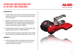
ASSEMBLY AND OPERATING
INSTRUCTIONS FOR
AL-KO AKS 2700 STABILISER
PLEASE ENSURE YOU READ THESE INSTRUCTIONS CAREFULLY,
BEFORE COMMENCING TO OPERATE THIS PRODUCT.
REGULATIONS:
1) The AKS 2700 must be used in conjunction with 50 mm dia. towballs which conform to
EC Directive 94/20 (DIN 74058 or local equivalent).
2) Suitable for attachment to drawbars or approved overrun braking equipment for single axle
(and tandem axle) trailers, with a minimum weight of 200 Kg and a maximum permissible weight
of 2700 Kg.
3) EC design approval has been given to the AL-KO AKS 2700 coupling under permit
No. e1*94/20*0030*00.
4) This design approval has been recognised by all EC member states and must be
implemented with effect from 01.12.95.
RESTRICTIONS OF USE:
Spare wheels fitted to rear door of vehicle, or vehicle with platforms etc:
1) the AKS 2700 Stabiliser is based on the latest regulations. This means the new DIN 74070
(dimensions of couplings) are also adhered to.
2) The trailer coupling may only be connected to towing vehicles where the clearance for the
stabiliser can be observed, in accordance with Directive 94/20 EC (DIN 74058). If these
clearances are infringed by special attachments, then the use must be checked separately.
3) Not suitable for use with overrun devices which revolve above 25o.
4) For Swan Neck towbars (fixed or detachable), refer to clearances on separate towball sheet.
WARNINGS:
1) In accordance with EC Directive 94/20, couplings type A 50-1 cannot be used (see Fig. 2).
2) A bolted-in type ball coupling (Fig. 1) is only permissible if the thread is locked.
3) The AKS 2700 cannot be used with a laterally attached reversing lever, on the left side, when
facing direction of traffic.
Fig. 1
Storing:
AL-KO Kober Ltd
South Warwickshire Business Park
Kineton Road
Southam
Warwickshire, CV47 0AL
01926 818500 01926 818562
www.al-ko.co.uk
To reduce the contamination of component
parts of the AKS 2700, the stabilising handle
should be closed if stored over a longer period.
Protect the towball of the vehicle from rusting.
8
Part No. 1385107 Iss. 2 - 11/03
Fig. 2
This type of coupling must be locked to ensure it cannot revolve.
1
1. PLEASE CHECK THE CONDITIONS FOR
ATTACHMENT BY FOLLOWING THE STEPS
LISTED BELOW.
Clearances for AKS 2700 (Fig. 4):
a)
The area above the towing ball of the
vehicle must be free from vehicle
components (eg. spare wheels).
b)
Clearing for stabiliser handle = 340 (B)
+ stroke (D) (85-100 mm) = 440 mm
with AL-KO overrun devices.
c)
Max. 50 mm (C) clearance for coupling
handle (at initial operation).
d)
Min. 45 mm clearance (E) to rear of
towing vehicle.
Towing vehicle with towball attachment:
The equipment may only be used for connecting to towballs to Directive 94/20 EC A50,
where the clearance below the ball, is at least
60 mm (Fig. 3). According to British Standards
the prescribed rotation of ±250 will thus be
achieved. Not suitable for use with revolving
shafts above 250.
Use a screwdriver to remove plastic protective caps (fig. 22/Item 1).
Fig. 22
Checking the towball coupling:
Have the towball re-checked with standardised
test ball at the AL-KO service station. The
towball coupling/trailer ball is not worn at
handle (Fig. 23/A) (Tightening only via spring
force, without pushing by hand).
Fig. 23
Fig. 4
Fig. 3
Press worn friction linings (Fig. 22/Item 2)
inwards and remove (use punch and hammer
- replace one at a time).
Insert the new friction linings from below with
the pin in the sleeve (Fig. 22/Item 3) and press
in as far as possible (pin engages, no tools
necessary). Also reinsert adjusting washers, if
present on original friction pads.
Check wear on ball:
Handbrake lever on right:
The AKS 2700 can be used only on overrun
devices where the handbrake is mounted on
the right, viewed by someone facing the
direction in which the vehicle is moving. For
handbrake levers on the left, please order the
special handles, Part No. 581158 & 581158.
Table 1
Min Total
Mass Permissble
Kg
Weight Kg
Nose
Weight
Kg
Weight
Kg
200
100
5
Distance
Length
D
(Fig. 5)
177
177
177
2700
Hole Shaft
Type Dia. (mm)
A (Fig. 5)
Horiz 50
35&40
Cross 46&51
2
Between Holes
B
50
54
40
C
12
12
18
If the wear indicator (Fig. 23/Zu) is no longer
visible, it is probable that the ball is worn and
has developed play within the coupling
housing. Proceed as follows:
Connect ball DIN 74058 (ISO 50)
Handle is automatically tightened
No pushing by hand
Check the position of the wear indicator
Fig. 24
Warning: The AKS 2700 can disengage and
the caravan could uncouple from the towing
vehicle. Check AKS and towball immediately!
Warning: Exchange the worn out part
immediately. The diameter of the towball
should be ascertained first of all, so that
conclusions may be drawn as to the wear of
the coupling mechanism (min dia. 49.61 mm).
7
Painted towballs or similar coatings: In the
event of the ball being coated, this must be
thoroughly removed (with 100-200 grain
sandpaper). Otherwise reduced stabilising
effect, increased wear and damage to AKS
2700 components may occur.
Lubrication:
Coupling Mechanism:
In order to maintain the easy action of the
coupling mechanism and to achieve a longer
life for the AKS 2700, the coupling mechanism
must be lubricated at regular intervals (at least
once a year). Type of lubricant: General
purpose grease to DIN 51825 KTA 3K (or local
equivalent). (Fig. 24).
Attention:
The shock absorber moves out independently
and for this reason, you will find a retaining
pin in the box, to facilitate coupling head
removal.
Fig. 5
Remove gaiter from coupling head.
Loosen and remove hexagon nuts
(Fig. 6/Item 1&2).
Pull or push out hexagon bolt
(Fig. 6/Item 1).
Knock through hexagon bolt
(Fig. 7/Item 2) with retaining pin (Fig. 7/Item 1)
and leave in retaining pin to secure shock
absorber (damper) in the drawbar.
The AKS 2700 is designed for drawshaft tubes
up to 50 mm dia. For small diameters, spacer
brackets are enclosed (Fig. 8).
Technical Information: The friction linings are
pressed against the towing ball and generate a
stabilising/damping force. The friction pads are
therefore subjected to wear. The linings have
Warning: When lubricating, no oil or grease
reserves of wear and thus have a long service should get on the friction area or the ball
life (Fig. 18).
holding area.
Fig. 18
If friction pads are contaminated with grease
they should not be cleaned as this will have a
reduced stabilising effect. Therefore friction
pads should be replaced.
Stabilising Unit:
Should lubrication of the stabiliser unit parts
become necessary then the following must be
observed:
a)
Clean all parts thoroughly.
b)
Areas may only be covered with a thin
film of grease (Fig. 21/Item 1).
c)
Type of lubricant: Multi-purpose grease
to DIN 51825 KTA 3K (or equivalent)
How to check the efficiency of the AKS 2700:
1)
2)
Couple the AKS 2700.
Pull stabilising handle into off position
(Fig. 19/Item 1).
3)
Close stabilising handle until resistance
is felt (friction linings are in contact with
the towball - but not under pressure).
4)
The mark on the pressure plate is
between the two marks (Fig. 19/Item 4)
on the housing (Fig. 19/Items 2&3),
5)
The friction linings are beyond
permissible wear range and require
adjustment, when the marking on the
pressure plate coincides or passes the
marking on the housing (Fig. 19/Item 3).
Fig. 19
Fig. 20
Warning: When lubricating, no oil or grease
should get onto the friction area or on the ball
holding area!.
Assembly of the AKS 2700 Stabiliser:
Place AKS (and spacers - if required) (Fig. 9/
Item 3) onto the drawshaft, aligning mounting
holes 1&2 and spacer sleeve
(Fig. 9/Item 4).
Insert hexagon bolt M12x80/75 (Fig. 9/Item 1)
and take up spacer sleeve (if used).
All EC Countries:
The installation is to be examined in conformity
to the stipulations in Appendix 1, No.5.10,
according to the demands of Appendix VII of
Directive EC 94/20. These installation and
operating instructions are to be included with
the caravan/trailer papers.
Fig. 6
GB - Installation only possible with special tow
ball attached to towing vehicle. Towball label
will appear as follows:
Fig. 7
Fig. 21
(see regulations and restrictions of use on
page 1).
Replacing Friction Linings:
The marking on the pressure plate (Fig. 19/
Item 4) has reached or passed the “replace”
marking on the housing (Fig. 19/Item 3).
Uncouple the AKS 2700.
6
Fig. 8
2. ASSEMBLY INSTRUCTIONS
50 mm = no spacer required
40 mm = Spacer (a) required
35 mm = Spacer (b) 5.5 mm
(1x5.0 mm & 1x2.5 mm)
45 mm = Spacer (c) 2.5 mm
Removal of existing coupling head:
Before you begin dismantling the coupling
head, please note the following:
The shock absorber (damper) on most overrun
equipment is suspended on the rear fixing bolt
(Fig. 6).
3
b)
Overrun device
- drawshaft telescoped out
- drawshaft telescoped in
- handbrake lever on
- handbrake lever released
The free room is required to guarantee correct
functioning and ease of operation.
Warnings:
Always insert horizontal bolts from stabiliser
lever side, as this allows correct clearances
and theft prevention if used with AL-KO barrel
lock (not included).
Always insert vertical bolt from top to bottom
and re-use original shim used on the overrun.
(Fig. 10/Item 1).
Fig. 9
Fig. 11
Fig. 11a
Fig. 10
Knock through retaining pin with hexagon bolt
M12x80/75 (Fig. 9/Item 2). Shock absorber
(damper) will remain in place.
3. OPERATING INSTRUCTIONS
For your own safety please check:
To ensure shock absorber (damper) is retained
in place, push drawshaft in and out.
If resistance is felt when pulling the drawshaft
out, then the shock absorber (damper) is in
place.
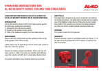
AKS 2700 Delivery Specifications:
Fig. 12/Item 1: Stabilising Lever
Fig. 12/Item 2: Coupling Handle
Place the lock-nut (use the new nuts enclosed)
onto the bolt and torque to 100 Nm.
Warning: Self-locking nuts may only be used
once.
Please Note: When coupling or uncoupling, the
stabiliser lever must be in the top position
(open).
Depending on design of gaiter may either be:
- put over coupling
- linked into space bracket
- fixed over retaining ring.
IMPORTANT:
In any operating condition, there must always
be free room of approx. 25 mm between the
AKS controls and the operating parts of the
overrun device, so that a hand can be inserted.
(Figs. 11/11a)
This should be checked as follows:
a)
AKS 2700
- stabiliser handle closed
- stabiliser handle open
Coupling/Uncoupling:
Pull stabiliser handle fully up right to stop
(open) (see Fig. 14/Item1).
Fig. 12
Fig. 13
4
Fig. 14
Coupling Up:
Fig. 15
Fig. 16
Coupling Head:
Open the ball coupling - to do this, pull coupling
handle fully upwards in direction of arrow (Fig.
14/Item 2).
Put the opened coupling on the towball of the
towing vehicle and release the coupling handle. Safety Tips:
It should now slide back into the initial position
on its own. However, press down with the
During coupling and uncoupling, the AKS 2700
hand as well. Closure and fastening are
must only be operated by one person.
automatic.
Safety Warning: If the stabiliser is correctly
coupled to the towball, then the green edge of
the safety indicator is visible. The coupling
mechanism is correctly positioned when the
hand lever can no longer be pressed down
even by hand (Fig. 15/Item 3).
If the AKS 2700 is not correctly coupled to
the towball, then the trailer/caravan can
become disconnected from the towing
vehicle!
Press the stabilising handle down until it is over
centre and against the end stop.
Warning; Never operate with foot or extension
bar! The components will be overloaded and
damaged. (Fig. 16).
Only press stabilising handle down or pull it up
with one-hand only.
Warning: The stabilising lever must not be
used as an aid for manoeuvring.
Caution: When opening or closing stabilising
handle, do not leave hands on the coupling
handle (Fig. 17).
Fig. 17
Uncoupling:
Lower the jockey wheel.
Detach breakaway cable and electrical plugs.
Pull stabilising lever up, right to stop (Fig. 13/
Item 1).
Pull coupling handle hard up in direction of
arrow (Fig. 14/Item 2).
Lift coupling head from towball of towing
vehicle. This process can be carried more
easily if the towbar is set high with the jockey
wheel, when the coupling handle is opened.
Important Operating Factors:
The towball should be completely free of
grease and other residue. Clean thoroughly
with Thinners, White Spirit or Brake Cleaning
fluid.
Hints: The surface of the towball must be free
of grooving, rust and scratch marks, otherwise
increased wear and tear will occur. If pads are
contaminated by paint or if they are glazed,
they can be cleaned with 100-200 grain
sandpaper.
5