1
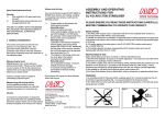
Installation and operating instructions Domestic hot water heat pump » wwk 300 » WWK 300 SOL ECO ON °C OFF 1x >60°C Index Page Specification Special accessories Operating instructions - for users 1 Operation and control 1.1 Equipment description 1.2 Correct operation 1.3 Incorrect operation 1.4 Description of functions 1.5 Operation outside the scope of applications 1.6 Maintenance and cleaning 1.7 Operation and control 1.8 Troubleshooting by users Installation instructions - for contractors 2 Safety equipment and maintenance 2.1 On the equipment 2.2 On the system 3 Installation 3.1 Transport 3.2 Positioning 3.3 Water connection 3.4 Boiler connection 3.5 Electrical connection 4 Commissioning 5 Shutting the equipment down Environment/recycling Customer service/warranty Specification 2 2 3 3 3 3 3 3 3 4 4 Type WWK 300 WWK 300 SOL Part no. 074361 074362 Operational limits of the heat pump °C +6 to +35 +6 to +35 DHW temperature °C +25 to +55 (adjustable) +65 (fixed) +25 to +55 (adjustable) +65 (fixed) Heat pump Electric heating element Air volume / throughput m3/h 550 550 l 303 284 Cylinder capacity Refrigerant / filling volume -- / g R 134a / 850 mm 1792 / 660 / 690 Dimensions H / W / D kg 150 / 453 Weight dry / filled 5 5 5 6 6 6 6 7 8 9 9 9 9 Voltage / frequency V/Hz L/N/PE ~ 230 / 50 PN max. (ttl. power cons.) / fuse kW / A 2.0 / 16 gL R 134a / 850 1792 / 660 / 690 180 / 464 L/N/PE ~ 230 / 50 2.0 / 16 gL Water connections (male thread) mm Ø 22 (outside) Ø 22 (outside) Circulation connections (male thread) inch G ½ G ½4) Condensate connection mm Ø 20 Ø 20 bar 6 6 Maximum power consumption Heat pump kW 0.53 0.53 Heating capacity HP kW approx 1.6 approx 1.6 4) Permitted pressure, water side 1) COP (t) 2) 4.2 4.2 kW 1.5 1.5 2) Power consumption Electric heating element Condenser Safety heat exchanger Heat exchanger for external DHW heating (type SOL) Information for owners Keep these operating instructions safely and pass them on to any new user, should the equipment change hands. Let your contractor check their content in conjunction with any maintenance or repair work. Positioning, installation and commissioning must be carried out by trained contractors, in accordance with these operating and installation instructions. The manufacturer’s warranty only applies, if the WWK 300 is installed, connected and operated in accordance with these operating and installation instructions. In conjunction with the positioning/ installation, observe all local/national standards and requirements, as well as the stipulations by your local water board and energy supply company. Pressure drop - heat exchanger (1000 l/h) hPa - Pressure drop - heat exchanger (1500 l/h) hPa - Heating capacity - heat exchanger3) at flow temp. 55 °C (flow rate: 1000 l/h) kW - Material Content l Permitted pressure bar Permitted flow temperature °C mm Water con. heat ex. (male thread) 3) 1) 2) 4) - 1.3 8 St-em 11 10 95 4.5 13.7 Ø 22 (outside) Test point at 35 °C air temperature, 70 % rel. humidity and 55 °C water temperature. Average value at 15 °C air temperature, 70 % rel. humidity, and heating water from 15 °C to 55 °C. At an average temperature difference ∆T = 30 K (difference between the average heat exchanger temperature and the average cylinder temperature). ISO 7-1. Additionally PK 9 Air channel adaptor m2 Heat exchanger surface Order.-No. 18 21 38 07 14 48 Description Condensate pump For connection to air hoses / channels160 and 200 mm dia. (circular) Operating instructions for users and contractors 1 Operation and control The WWK 300 domestic hot water (DHW) heat pump from STIEBEL ELTRON is an automatic DHW heater offering a capacity of approx. 300 l. The required DHW temperature can be preselected. Your local contractor will install, connect and commission your WWK. Nevertheless, you should familiarise yourself with the most important aspects of this equipment. 1.1 Equipment description The WWK 300 contains two heat sources within the cylinder; both heat the water to the required temperature: – Heat pump – Electrical supplementary heater The WWK 300, with suffix SOL, not only contains a heat pump and an electrical supplementary heater, but also a heat exchanger permanently fitted inside the cylinder, which can be supplied with energy from a boiler or solar heating system. The WWK 300 extracts energy from the air which can be utilised to heat the water contained inside the cylinder. This energy extraction leads to a cooling of the installation room by approx. 1-3 °C. The WWK can also be operated with a connection to an air duct (for part no., see page 2). However, such air channels must not be smaller than Ø 160 mm; their length should not exceed a maximum of approx. 5 m. The WWK 300 also extracts moisture from the air, which turns into condensate and must be drained off. A hose connection is provided for that purpose. 1.2 Correct operation This DHW heat pump is designed to extract energy from the air inside the equipment installation room or from a room, to the ambient air of which it is connected, via air ducts. With that energy it heats domestic hot water (DHW). 1.3 Incorrect operation Never – use greasy exhaust air – heat liquids other than potable water – install the equipment a) outside b) in rooms at risk from frost c) in rooms at risk from dust, gases or vapours liable to explode – operate the equipment with an empty cylinder – operate the integral heat exchanger inside the equipment cylinder with liquids other than heating water. 1.4 Description of functions 1.4.1 Heat pump operation This is the standard operating mode, to which the limits of scope of the heat pump apply (see: specification). To heat the cylinder content of approx. 300 litres of water to 55 °C, the WWK 300 (to EN 255 part 3) requires: ϑ Space H rel ϑ Cold water τ Heat-up COP(t) 6 °C 15 °C 35 °C 70 % 70 % 47 % 15 °C 15 °C 15 °C 11.5 h 9.0 h 6.4 h 3.3 4.2 5.2 The water inside the cylinder will be heated to 55 °C by the electrical supplementary heater, which is controlled by the programmable time switch, subject to the heating period being long enough. This enables the option of making greater mixing water volumes available at certain times. At all other times, the water will be heated to the temperature selected on the controller (see page 4, Fig. 1, item 3). If the heat pump was manually switched OFF and ON again after a power failure, the compressor will only re-start (after approx. 15 minutes) when the pressure inside the refrigerant circuit has normalised again. 1.4.2 Electrical supplementary heater You can accelerate the heating-up process with the electrical supplementary heater, if the DHW demand increases or if the WWK 300 has previously been switched OFF and you require hot water as quickly as possible. For reasons of saving energy, the electrical supplementary heater only heats the top third of the cylinder capacity (approx. 100 litres). This takes approx. 2 hours. In SOL versions, approx. 50 litres are heated up due to the flange being positioned higher up on the cylinder. The electrical supplementary heater is switched ON when the actual temperature falls below 58 °C and is switched OFF when 65 °C are exceeded. Press the push button only once if you want to activate the electrical supplementary heater only to cover a peak demand. 1.5 Operation outside the limits of use below 6 °C to 4 °C Subject to the relative humidity and the DHW temperature inside the cylinder, the evaporator begins to ice up below a room temperature of 6 °C. When the evaporator is covered in hoarfrost, the frost stat N2 (see wiring diagram) shuts down the compressor, whilst the fan continues to operate, thereby defrosting the compressor. The compressor starts again automatically after the defrosting process has been completed, and the heat pump operation continues. The minimum temperature required for the heat pump operation is +4 °C. The evaporator is defrosted upon demand at operating temperatures between +4 and +6 °C. This increases the heat-up time. Room temperature higher than 35 °C The heat pump will be switched OFF by safety equipment at room temperatures above approx. 35 °C. The heat pump will be restarted automatically after a brief cooling down period. The heat pump will be switched OFF again if the room temperature is still higher than 35 °C. Take appropriate steps to prevent the ambient temperature rising above 35 °C. 1.6 Maintenance and cleaning The WWK 300 is largely maintenance free. Maintenance must only be carried out by qualified contractors. Have the protective anode checked regularly. Your contractor, who will be familiar with your local water quality, will advise you of the optimum timing for such maintenance. The first inspection of the protective anode is due after two years. 1.4.3 Boiler operation via heat exchanger (only for SOL version) A heat exchanger, which is generally connected to a central heating system, is integrated into the cylinder. Subject to the heating water flow temperature, the entire cylinder capacity should be heated up by the heat exchanger in between 3 and 4 hours. Never exceed the maximum inlet temperature of 65 °C into the heat pump heat exchanger. 1.7 Operation 1.7.1 Overview of the user interface 3 (N1) 1 (S1) ECO ON °C OFF >60°C C26_03_01_0312 1x Description in brackets, see wiring diagram Fig. 8, page 8 4 (S5) 2 (S2 / H1) Fig. 1 Function WWK 300 / WWK 300 SOL Only heat pump operation 25 °C to 55 °C. Single reheating via the electrical heater rod to 65 °C. Programmed start of the electrical heater rod via the time switch. 1.7.2 Description of functions – Switch (1) switches the entire heat pump ON (I) or OFF (0). – Using push button (2), you can activate a single quick heat-up of the cylinder via the electrical supplementary heater. After the top third of the cylinder capacity has reached a DHW temperature of 65 °C, the electrical supplementary heater is switched OFF, but is not automatically switched ON again. – An indicator lamp is integrated into push button (2), which lights up when the electrical supplementary heater is switched ON. – Select the DHW temperature with the rotary selector (3) of the thermostat, Fully clockwise approx. 55 °C ECO approx. 40 °C (frost protect. stage) approx. 25 °C In position ECO, the heat pump operates more efficiently than at the r.h. end stop. You will need to establish the DHW temperature you require, because a higher temperature would result in a larger volume of DHW at approx. 40 °C (temperatures for baths and showers are generally around 40 °C). – The time switch (4) is equipped with a week disk comprising 84 switching Main ON/OFF switch (1) ON ON ON Push button (2) Clock (4) programmed – 1x – – – Yes segments. The shortest switching period is 2 hours long. Segments pressed inwards towards the disk centre (approx. 2 mm lift) are switched ON. – The DHW display sensor captures the DHW temperature inside the upper third of the cylinder (approx. 100 litres). 1.8 Troubleshooting by the user 1.8.1 No hot water Should you fail to obtain hot water at any time, you can take the following steps to remedy that situation. No electrical power Check the fuse/circuit breaker in your fuse box. If it has blown/tripped, replace/reset the fuse/MCB. Notify your local contractor, if the MCB trips/fuse blows again when you insert the mains plug into the socket again. Still no hot water, even though power is available Check, whether the air inlet/outlet is unobstructed. The thermoswitch trips out or the high limit safety pressure limiter switches the compressor OFF if the compressor is overloaded due to excessive ambient temperature or excessive extract temperature (>35 °C), or because of a fault in the refrigerant circuit. Ask your local contractor to remove the relevant fault. The thermoswitch automatically switches itself ON again. The high limit safety pressure limiter must only be reset by your contractor after he has removed the cause of the relevant fault. 1.8.2 Other faults Safety valve of the cold water supply line drips This may occur during the heat-up phase and is completely normal. Condensate drain drips This always happens when the surface temperature of the evaporator is lower than the ambient dew point temperature. For all other faults, consult your contractor. DHW heating can be maintained in most fault conditions by switching the electrical supplementary heater ON. Installationinstructionsforcontractors 2.1Ontheequipment Incaseofafault,thesafetyequipmentofthe WWK300interruptstherelevantpowercircuit. Such faults can, for example, be caused by a faulty DHW priority setting on a connected boiler. Pull the mains plug out its socket before commencing any work on the equipment. High limit safety cut-out (STB) Thiswillshuttheequipmentdownifthe DHWtemperatureexceeds95°C.Resetthe highlimitsafetycut-outbypressingthereset button(item,Fig.3),afterthecauseofthe faulthasbeenremoved.Forthis,openthe equipmentasshowninFig.a. Safety high pressure limiter (SDBK) Thesafetyhighpressurelimitershutsdown thecompressor,ifthepressureinsidethe refrigerantcircuitexceedsthepermissble maximumvalue.Thesafetyhighpressure limitermayalsorespond,iftheWWK300is operatedaboveitspermissiblelimit(>35°C exhausttemperature).Resetthesafetyhigh pressurelimiterbypressingtheresetbutton (item1,Fig.3),afterthecauseofthefaulthas beenremoved.Forthis,opentheequipment asshowninFig.a. When replacing the front facia ensure that the earth cable is correctly connected. Cleaning the evaporator MaintainingthefulloutputoftheWWK300 requiresanoccasionalprofessionalcleaningof theevaporator.Yourcontractorwilldetermine thetimingforthisoperation. 2.2 Onthesystem Safety valve (on-site provision) Thisvalveopenswhenthewaterpressure exceedsthepresetvalueof6bar,thereby relievingthepressure.Itisadjustedsothat nowaterwillbeexpelledwhenheatingis switchedOFF.Shoulditcontinuetodrip ECO excessively,eitherthevalveseathasbecome contaminated,thewaterpressureistoohigh orthepressurereducingvalvehasbecome faulty. Pressure reducing valve (on-site provision) Checkthevalveforperfectfunction.Replace it,ifnecessary. Regular valve maintenance Safetyrequiresthatvalvesareregularly checkedforperfectfunction.Howquickly limescalebuildsupdependsonthelocal waterquality. Asyourlocalcontractorisfamiliarwithyour localwaterquality,lethimdeterminethe timingofthischeck. ON °C OFF 1x >60°C 6_03_01_0313 2Safetyequipmentand maintenance Fig.a Fig.b Theprotectiveanodeislocatedbehindthe frontfascia.Whenremovingthefascia,please notethattheearthstraptothefasciaisnot pulledoff(Fig.b).Ifrequired,removethe strapfromthepush-onconnector. 1 C6_03_01_0009 Protective anode AprotectiveanodeisintegratedintotheDHW cylindertoprotectitagainstcorrosion. Theprotectiveanodeispushedthroughthe flangefrominsideoutandsecured.For inspections,theflangewillberemovedto enablethesimultaneousinspectionofthe electrode,theheaterrodandtheinternal enamelcoating.Whenreplacingtheanode, ensureaperfectcontactwithametallic, conductivesurfaceduringassembly.The timingoftheinspectionissubjecttothelocal waterqualityandisdeterminedbyyourlocal contractor(StiebelEltronrecommendsthatthe firstinspectiontakesplacenolaterthanafter twoyears). 6_03_01_0315 Protective motor switch Theprotectivemotorswitchwillshutdown thecompressorifitisoverloadedbecauseof excessivethermalload.Removetherelevant fault.Afterashortwhile,theprotective motorswitchwillrestartthecompressor automatically. Fig.3 5 3 Installation Positioning ECO ON °C OFF 688 100 C26_03_01_0314 Min. 2150 >60°C 1800 1x Air Air Min. 400 660 The available floor area in the installation room must be at least 6 m². Never install this equipment in rooms with a volume of less than 13 m³. Never restrict the ambience around the WWK 300 through walls or ceilings closer than shown in Fig. 4. The room temperature must never fall below +6 °C, as the ambient temperature will be reduced by approx. 1-3 °C through the heat pump operation. The initial temperature level will be re-established approx. ½ hour after the heat pump has been switched OFF. 3.1 Transport To protect the equipment against damage, it must be transported vertically inside its dedicated packaging. Where space is restricted, you may also move the equipment tipped backwards at an angle. Min. 400 3.2 Positioning 1. Unscrew the four screws from the nonreturnable pallet. 2. Remove the washers. 3. Before removing the equipment from the pallet, remove the anti-vibration mounts from the pack supplied with the equipment, and insert fully into the equipment. 4. Remove the equipment from its pallet and position it where required. 5. Level the equipment by manipulating the anti-vibration mounts. When installing the heat pump in a boiler room, ensure that the boiler will not be impaired. 3.3 DHW connection Observe the regulations imposed by your local water board. Install the cold water supply line in accordance with Fig. 5. Checking installation conditions The room where the WWK 300 is be installed must meet the following conditions: To facilitate an easy connection to the water system, the equipment will be supplied (in a separate pack) with angled plug-in fittings, pipe connectors with union nuts and flat gaskets. Fitting the plug-in connector (see page 9.) Stable floor (WWK 300 wet weight approx. 455 kg). Never operate the WWK 300 in rooms, at risk from explosion due to dust, gases or vapours. Include in your considerations the utilisation of waste heat, for example from a boiler, tumble drier or refrigerator/ freezer. Dimensions in mm Fig. 4 Connection dimensions To protect against the risk of corrosion, make the connection as flat packing seal. The use of hemp on connections is not acceptable. 159 1 2 3 4 5 3 15 9 2 TWW 6 7 8 9 10 11 12 13 14 16 6 22-40 adjustable 56 194 376 558 1055 12 1264 1438 4 7 TW 1 5 8 10 11 12 13 14 15 16 Cold water supply Ø 22 mm DHW connection Ø 22 mm Condensate drain ½” - hose connection Circulation connection G ½” ½” nipple for collector or boiler sensor Heating water flow Ø 22 mm Heating water return Ø 22 mm Drain valve Safety valve Straight-through shut-off valve Test port for pressure gauge Non-return valve Test valve Pressure reducing valve (only in case of > 4.8 bar pressure) Electrical cable grommet DHW circulation pump 10 Fig. 5 C26_03_01_0315 32 Dimensions in mm 3.4 Connection examples We recommend the following combinations when using metal pipework for the installation: Cold water line DHW line Copper pipe Steel pipe Copper pipe Steel or copper pipe Reheat with solar collector Insulate the DHW line in accordance with local regulations. Please adhere to the order of fittings on the cold water side precisely (see Fig. 5). Prior to installation: Flush out the line. Install the safety valve into the cold water line. The expansion water must be able to be seen to drip into a basin or funnel. The diameter of the connecting pipe must not be larger than the safety valve diameter. Size the drain so that water can drain off, even if the safety valve has been fully opened. The outlet must not be able to be blocked/closed off. The safety valve must open at 6+1 bar. Install a drain valve at the lowest point of the cold water supply line. Install a pressure reduction valve when the water pressure is higher than 5 bar. Special measures are required at water pressure above 10 bar (see Fig. 5). Condensate drain The condensate from the WWK 300 is channelled to a drain via a hose (½” dia.). Where necessary, install a condensate pump (for part no., see page 2). C26_03_01_0016 DHW Cold water safety assembly Reheat with boiler Connecting a circulation line to the cylinder The heat losses incurred in the circulation line and the electrical power consumption of the circulation pump, reduce the efficiency of the system. The cooled down water in the circulation line mixes with the cylinder content. Where possible, avoid installing a circulation line. Where that is not possible, control the circulation pump thermally or by a time switch. C26_03_01_0010 DHW 3.4 Boiler connection (WWK 300 SOL) Pipe bends with union nuts are supplied with equipment which has heat exchangers installed, to enable easy connection to a boiler. Such connection is only permitted with boilers providing DHW priority and in conjunction with an electronic temperature sensor operating with low voltage (capturing the cylinder temperature of the heat pump). The sensor well is located on the front of the heat pump behind the lower door. The DHW Cold water safety assembly 1 2 3 4 5 6 7 8 9 10 DHW heat pump DHW cylinder probe Solar circulation pump Safety valve Non-return valve Central heating circulation pump Mixer circuit circulation pump Expansion vessel Shut-off valve Fill & drain valve 11 12 13 14 15 16 17 18 19 Solar collector Boiler Air vent valve Collector sensor Outside temperature sensor Mixer valve probe Mixing valve Solar control unit Boiler control unit Fig. 6 temperature is adjusted at the boiler control unit. Control panel WWK 300 / WWK 300 SOL 3.5 Electrical connection The WWK 300 is supplied fully wired. A 230 V / 50 Hz socket is required. Line fuse rating: 16 A gL. C26_03_01_0017 A cable grommet is provided at the back of the heat pump to enable control equipment to be connected (temperature sensor). Before plugging in the mains plug, set switch (1) (Fig. 1) OFF (0). Fill the cylinder with water. X1 Z1 K1 N3 N2 Fig. 7 Wiring diagram WWK 300 / WWK 300 SOL Electric heater rod High limit safety cut-out Pressure limiter Protective motor switch (Klixon) Indicator lamp -- electric heater (S2) Relay Compressor Fan Heat pump controller Hoarfrost temperature monitor 65 °C limiter Main ON/OFF switch Push button “E heater rod 1x” Week time switch Mains supply Capacitor C26_03_01_0011 1/N/PE AC 50Hz 230V E1 F1 F3 F4 H1 K1 M1 M2 N1 N2 N3 S1 S2 S5 X1 Z1 Fig. 8 4 Commissioning 3. Environment and Recycling Your local contractor must implement the commissioning: Fill the cylinder to prevent damage to the compressor and radiators. For filling, open the water valve, until water flows out. Recycling of obselete appliances Appliances with this label must not be disposed off with the general waste. They must be collected separately and disposed off according to local regulations. Open the safety valve, until water flows out free of bubbles. Then close the safety valve. – Starting the WWK 300: Set switch 1 to ON. 4. Guarantee – Supplementary heater: Press push button 2; the indicator lamp inside the push button lights up For guarantees please refer to the respective terms and conditions of supply for your country. – Set the temperature selector 3 Fully clockwise. The installation, electrical connection and first operation of this appliance should be carried out by a qualified installer. – Set the time at clock 4. The company does not accept liability for failure of any goods supplied which are not installed in accordance with the manufacturer‘s instructions. Inform the user that water may drip from the safety valve whilst the water is being heated up. 5 Shutting the equipment down Puul the mains plug for reasons of frost protection and good hygiene, drain the cylinder if it is taken out of use for longer periods Fitting the plug-in connector The plug-in connectors are equipped with a retainer with stainless steel serrations and an O-ring for sealing. In addition, they are designed with the "Twist and secure" function. By simply turning the screw cap manually, the pipe is secured in the connector, and the Oring is pushed against the pipe to seal it. Making the connection The fitting must be in its released state before inserting the pipe. In this position, there is a small gap between the screw cap and fitting body. Push the pipe past the O-ring until it bottoms out inside the connector. Tighten the screw cap unit it meets the casing. This presses the O-ring against the pipe and secures the connector. Gap between the screw cap and the casing (released position) ca. 33 mm Releasing the connection Turn the screw cap back until a small gap appears. Turn the retainer back by hand and hold it in position. The pipe can now be pulled out again. Notes 10 Notes 11 Deutschland STIEBEL ELTRON GmbH & Co. KG Dr.-Stiebel-Straße | D-37603 Holzminden Tel. 0 55 31 702 0 | Fax 0 55 31 702 480 Email [email protected] www.stiebel-eltron.de Verkauf Tel. 0180 3 700705 | Fax 0180 3 702015 | [email protected] Kundendienst Tel. 0180 3 702020 | Fax 0180 3 702025 | [email protected] Ersatzteilverkauf Tel. 0180 3 702030 | Fax 0180 3 702035 | [email protected] Vertriebszentren Tel. 0180 3 702010 | Fax 0180 3 702004 Austria STIEBEL ELTRON Ges.m.b.H. Eferdinger Str. 73 | A-4600 Wels Tel. 072 42-47367-0 | Fax 07242-47367-42 Email [email protected] www.stiebel-eltron.at Great Britain Exclusive Distributor. Applied Energy Products Ltd. Morley Way | GB-Peterborough PE2 9JJ Tel. 087 09-00 04 20 | Fax 017 33-31 96 10 Email [email protected] www.applied-energy.com Czech Republik STIEBEL ELTRON spol. s r.o. K Hájům 946 | CZ-15500 Praha 5-Stodůlky Tel. 2-511 16111 | Fax 2-355 12122 Email [email protected] www.stiebel-eltron.cz Denmark Exclusive Distributor. PETTINAROLI A/S Madal Allé 21 | DK-5500 Middelfart Tel. 63 41 66 66 | Fax 63 41 66 60 Email [email protected] www.pettinaroli.dk France STIEBEL ELTRON S.A.S. 7-9, rue des Selliers B.P. 85107 | F-57073 Metz-Cédex 3 Tel. 03 87 74 38 88 | Fax 03 87 74 68 26 Email [email protected] www.stiebel-eltron.fr Hungary STIEBEL ELTRON Kft. Pacsirtamezo´´ u. 41 | H-1036 Budapest Tel. 012 50-6055 | Fax 013 68-8097 Email [email protected] www.stiebel-eltron.hu Netherlands STIEBEL ELTRON Nederland B.V. Daviottenweg 36 | Postbus 2020 NL-5202 CA‘s-Hertogenbosch Tel. 073-6 23 00 00 | Fax 073-6 23 11 41 Email [email protected] www.stiebel-eltron.nl Poland STIEBEL ELTRON sp.z. o.o ul. Instalatorów 9 | PL-02-237 Warszawa Tel. 022-8 46 48 20 | Fax 022-8 46 67 03 Email [email protected] www.stiebel-eltron.com.pl Russia STIEBEL ELTRON RUSSIA Urzhumskaya street, 4. | 129343 Moscow Tel. (495) 775 3889 | Fax (495) 775-3887 Email [email protected] www.stiebel-eltron.ru Irrtum und technische Änderungen vorbehalten | Subject to errors and technical changes! | Sous réserve d‘erreurs et de modifications techniques! · Onder voorbehoud van vergissingen en technische wijzigingen! | Salvo error o modificación técnica! | Rätt till misstag och tekniska ändringar förbehålls! | Excepto erro ou alteração técnica | Zastrzeżone zmiany techniczne i ewentualne błędy | Omyly a technické změny jsou vyhrazeny! | A muszaki változtatások és tévedések jogát fenntartjuk! | Âîçìîæíîñòü íåòî÷íîñòåé è òåõíè÷åñêèõ èçìåíåíèé íå èñêëþ÷àåòñÿ 8250 Switzerland STIEBEL ELTRON AG Netzibodenstr. 23 c | CH-4133 Pratteln Tel. 061-8 16 93 33 | Fax 061-8 16 93 44 Email [email protected] www.stiebel-eltron.com Thailand STIEBEL ELTRON Asia Ltd. 469 Moo 2, Tambol Klong-Jik Ampur Bangpa-In | Ayutthaya 13160 Tel. 035-22 00 88 | Fax 035-22 11 88 Email [email protected] www.stiebeleltronasia.com United States of America STIEBEL ELTRON Inc. 17 West Street | West Hatfield MA 01088 Tel. 4 13-247-3380 | Fax 413-247-3369 Email [email protected] www.stiebel-eltron-usa.com 264905/34546/4/8250 · HD Belgium STIEBEL ELTRON Sprl / Pvba P/A Avenue du Port 104, 5 Etage B-1000 Bruxelles Tel. 02-4232222 | Fax 02-4232212 Email [email protected] www.stiebel-eltron.be Sweden STIEBEL ELTRON AB Friggagatan 5 | SE-641 37 Katrineholm Tel. 0150-48 7900 | Fax 0150-48 7901 Email [email protected] www.stiebel-eltron.se