1
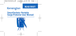
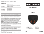
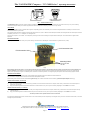
The ‘NAVIGATOR’ Compass - ‘NV-2400 Series’-
Operating Instructions
Ref: – OP/NV-2400/01 Iss:2
The NAVIGATOR - 2400 is a precision compass suitable for installation into Light Aircraft. To obtain the optimum performance you should ensure that you carry out the following
instructions carefully. We advise you to read through these instructions and notes before attempting to mount the unit in your aircraft.
THE COMPASS
The NAVIGATOR - 2400 compass is provided with a magnetic compensating system, which will enable you to minimise the magnetic disturbances created by the mechanical and
electrical characteristics of your aircraft.
The Compass Card is graduated in 5-degree increments with cardinal points at N, S, E & W. Because of the limited space available, the markings between the cardinal points should be
multiplied by a factor of 10. i.e. 3 = 30 degrees, 24 = 240 degrees etc.
The level of the compass – Front to Back – can be adjusted by loosening the rear screw and rotating the compass about the swivel point. The screw should be re-tightened after
adjustment.
POSITION OF MOUNTING
The compass should be mounted centrally on top of the ‘Coaming’ and attached with 3 ‘Non-Magnetic’ screws of diameter no greater than 4mm (0.156”).
N-S Correction Hole
E-W Correction Hole
Mounting Holes
2 off at front and
1 at rear
Fig 1
Before finalising the mounting point, it is a good idea to temporarily mount the compass in its intended position and “Swing“ the aircraft to see if the initial deviations are
less than 30 degrees. If the deviation for each cardinal point is less than 30 degrees then proceed with the mounting procedure described below. If the errors are greater than 30
degrees, then try mounting the compass in a different position. If this does not resolve the problem, local de-gaussing may be required to reduce the disturbing magnetic influence.
ADJUSTING YOUR COMPASS
Before your compass can be adjusted the aircraft must be capable of being aligned to both the East /West axis and North/South axis.
The use of another compass outside the aircraft, to determine the cardinal points is advised.
These following notes should be used for initial installation guidance only, the corrections should be checked or made by a qualified Compass Adjuster before flying.
CORRECTION EAST/WEST (‘B’ Coefficient)
1)
2)
Align your aircraft facing East, insert the Corrector Key provided, into the Left hand hole at the front of the compass, rotate the key in either direction so that the East point is
directly under the Index line.
Align your aircraft facing west and check that the West Point is under the Index line, Any error may be corrected by readjusting to remove HALF the error shown.
CORRECTION NORTH/SOUTH (‘C’ Coefficient)
1)
2)
.
Align your aircraft facing North, insert the Corrector Key into the Right hand hole at the front of the compass, rotate the key in either direction so that the North point is directly
under the Index line.
Align your aircraft facing South and check that the South point is under the Index Line. Any error may be corrected by readjusting to remove HALF the error shown
The above procedures can be repeated until the errors are minimised.
If the adjustments detailed above result in consistent errors on each of the Cardinal points the compass may not be aligned correctly on the Fore and Aft line of the aircraft, to correct this
mis-alignment proceed as follows: -
Compass House • Bowes Estate • Wrotham Road • Meopham • Kent • DA13 0QB • England
Tel: 44(0)1474-816320 Fax: 44(0)1474-816321 email: [email protected] website: www.sirs.co.uk:
Page 1
Fig 2
Fig 3
CORRECTION FOR MIS-ALIGNMENT (‘a’ Coefficient)
Note:
Only follow this procedure if the results obtained so far do not reach or requirements.
Errors to the Left of the true heading should be prefixed with a plus sign (+). [Fig 2]
Errors to the right of the true reading should be prefixed with a minus sign (-). [Fig 3}
1)
2)
3)
4)
Align the aircraft facing North; record the compass error in Box A.
Align the aircraft facing South; record the compass error in Box B.
Align the aircraft facing East, record the compass error in Box C.
Align the aircraft facing West; record the compass error in Box D.
5)
Add the readings in Boxes A to D, enter the result in Box E. Divide the figure in Box E by 4,
record the result in Box F, this figure is the error due to mis-alignment and may be corrected as
follows.
Note the current magnetic heading, carefully loosen the two cross headed screws which secure the
compass to the bracket, rotate the compass body in the opposite direction to the error shown in Box F.
i.e. If the error in.Box F is +5 degrees, rotate the compass body by -5 degrees and vice versa. Carefully
tighten the two cross-headed screws without moving the compass body
CORRECTION TABLE
In this example the compass body would need to be rotated by -5 degrees
If having carried out these procedures the results are not satisfactory a new
location must be found. Before this can be done the NAVIGATOR must be
returned to it’s ZERO status by carrying out the following procedure.
1)
BOX
A (NORTH)
B (SOUTH)
C (EAST)
D (WEST)
E (TOTAL)
F (“E” / 4)
Sample Error
+15
+5
-10
+10
+20
+5
BOX
A
B
C
D
E
F
Remove the NAVIGATOR from the bracket by removing the two cross-headed screws, this will reveal the top plate with its four spindles with white lines across.
Using the key provided rotate the spindles until all the white lines are parallel across the top plate, this is the ZERO CORRECTION status
3)
ACTUAL ERROR
Choose another location for the NAVIGATOR and repeat the installation procedure.
Page 2