1
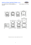
R6
Wood Burning Inset Stove
Installation and Operating Instructions
JINDLU06 Rev D 12/11/14
12
R6
Di Lusso, Emperor Way, Exeter Business Park, Exeter, United
Kingdom, EX1 3QS
DSEN13229 – Inset Wood Burning Stove
Appliance Mass
Efficiency
Nominal Heat Output
Mean Co Emission (@13% O2)
Mean OGC Emission (@13% O2)
Mean NOx (as NO2)
Mean Flue Gas Temperature
Flue Gas Mass Flow
Particulates (@13% O2)
116kg
76%
4.9 kW
0.20%
177 mg/m3n
79 mg/m3n
269 °C
5.8 g/sec
5.3 mg/m3n
NS3058/59
Average Particulate Emission
Maximum Particulate Emission
3.16 g/kg
3.27 g/kg
Minimum Clearance to Combustible Material
At the sides of the stove
400mm (from outside of frame)
In front of the stove (to furniture etc.)
1200mm
This appliance is not suitable for use in a shared flue
This appliance is suitable for intermittent burning
Smoke Control Areas
This appliance is only exempt for use in a smoke control area when fitted
with a smoke control area kit (JDLU0501)
Find out if you are in a Smoke Control Area by contacting your Local
Authority
Contents
General Guidance
Appliance Dimensions
Flue Requirements
Preparing the stove for installation
Direct Air Adaptor and Convection Duct kits
Installation into a solid non-combustible wall
• Hearth requirements
• Clearances to combustibles
• Fitting the stove
• Flue Connection
Installation into a non-combustible enclosure
• Enclosure Dimensions
Re-assembling the stove
Fitting the Frame Pack
Commissioning
Operating Instructions
• Recommended Fuel
• Air Controls
• Lighting
• Recommended Settings
• Refueling
• De-ashing
Maintenance
Troubleshooting
Spares
Page 1
Page 3
Page 3
Page 4
Pages 6 &10
Page 6
Page 7
Page 7
Page 8
Page 8
Page 9
Page 11
Page 12
Page 13
Page 14
Page 14
Page 15
Page 15
Page 16
Page 16
Page 16
Page 16
Page 17
Page 18
Pages 19-21
Guarantee
The body of the stove is covered under a five
year guarantee (from date of purchase) to be
free from defects in materials and
workmanship. Internal components other
than consumable items such as glass and
firebricks are covered for a period of one year
from date of purchase.
General Guidance
It is important that your stove is correctly
installed as Di Lusso cannot accept
responsibility for any fault arising through
incorrect use or installation.
These instructions cover the basic principles
to ensure satisfactory installation of the stove,
although detail may need slight modification
to suit particular local site conditions.
The installation must comply with current
Building Regulations, national and European
standards, Local Authority byelaws and other
specifications or regulations as they affect the
installation of the stove.
The Building Regulations requirements may
also be met by adopting the relevant
recommendations in the current issues of
British Standards BS 8303 and BS EN 15287-1.
COMPETENT PERSONS SCHEME
Di Lusso recommend that this stove is
installed by a member of an accredited
competent persons scheme e.g. HETAS.
If the installer is not a member of a
competent persons scheme, it is a legal
requirement in the UK to notify your local
building control body in advance of any work
starting.
HEALTH AND SAFETY P RECAUTIONS
Special care must be taken when installing the
stove such that the requirements of the
Health and Safety at Work Act are met.
1
PACKAGING
All packaging supplied with this stove can
be re-used or recycled. Please contact your
local authority for information on recycling
schemes in your area.
HANDLING
Adequate facilities must be available for
loading, unloading and site handling.
FIRE CEMENT
Some types of fire cement are caustic and
should not be allowed to come into contact
with the skin. In case of contact, wash
immediately with plenty of water.
ASBESTOS
This stove contains no asbestos. If there is a
possibility of disturbing any asbestos in the
course of installation then please seek
specialist guidance and use appropriate
protective equipment.
METAL PARTS
When installing or servicing this stove, care
should be taken to avoid the possibility of
personal injury.
AIR SUPPLY
The room or space containing this appliance
should have purpose provided ventilation
(where necessary) in accordance with Building
Regulations.
Due consideration should be given to air
requirements for any other appliance in the
same room or space.
Any air opening must be kept clear from
blockage or obstruction.
MODIFICATION
No unauthorized modification of this
appliance should be carried out.
SAFETY
•
WARNING – This appliance will be hot when
in operation and due care should be taken.
The supplied operating tool or gloves may be
used to open the door and operate the air
controls.
•
AEROSOLS – Do not use an aerosol spray on
or near the stove when it is alight.
FIRES CAN BE DANGEROUS – Always use a
fireguard in the presence of children, the
elderly or the infirm. The fireguard should be
manufactured in accordance with BS8423 –
Fireguards for use with solid fuel appliances.
DO NOT OVER-FIRE – it is possible to fire the
stove beyond its design capacity. This could
damage the stove so watch for signs of overfiring. If any part of the stove starts to glow
red, the stove is in an over-fire situation and
the controls should be adjusted accordingly.
Never leave the stove unattended for long
periods without first adjusting the controls to
a safe setting. Careful air supply control
should be exercised at all times.
FUME EMISSION – properly installed and
operated, this appliance will not emit fumes.
Occasional fumes from de-ashing and
refueling may occur. Persistent fume emission
must not be tolerated.
This appliance should not be operated with
the door open
If fume emission does persist then the
following action should be taken immediately
–
•
•
•
2
Open doors and windows to ventilate
room.
Let the fire out, or eject and safely
dispose of fuel from the appliance.
Check for flue/chimney blockage and
clean if required.
Do not attempt to relight the fire until
the cause has been identified and
corrected.
If necessary seek professional advice.
ADVERSE WEATHER – In a small number of
installations, occasional local weather
conditions (e.g. wind from a particular
direction) may cause downdraught in the flue
and the stove to emit fumes. In these
circumstances the stove should not be used. A
professional flue installer will be able to
advise on solutions to this problem (e.g. antidowndraught cowl).
EXTRACTOR FANS – DO NOT FIT AN
EXTRACTOR FAN IN THE SAME ROOM AS
THIS APPLIANCE.
IN THE EVENT OF A CHIMNEY FIRE •
•
•
•
•
•
Raise the alarm
Call the Fire Brigade
Close appliance air controls
Move furniture, ornaments etc. away
Place a fireguard in front of stove
Check the chimney breast for signs of
excessive heat.
If the wall is becoming excessively hot, move
furniture away. Ensure the Fire Brigade can
gain access to your roof space in order to
check for fire spread.
APPLIANCE DIMENSIONS
If there is no existing chimney then either a
prefabricated block chimney in accordance
with Building Regulations Approved
Document J or a twin-walled insulated
stainless steel flue to BS EN 1856 can be used.
These chimneys must be fitted in accordance
with the manufacturer’s instructions and
Building Regulations.
Flue Type
Masonry or flue block
flue with liner
Clay Flue Blocks
Clay/Ceramic Liners
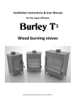
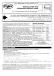
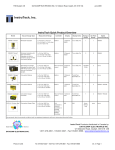
FLUE OUTLET POSITION
The flue outlet angle and position is
determined by the orientation of the flue
collar. The outlet can be either vertical or
leant backwards by 30°. To change the angle,
rotate the flue collar by 180°. The effective
centre dimensions in millimeters are shown
below.
Concrete Liners
Factory Made Metal
Chimney
Minimum Designation
T400 N2 D3 G
(BS EN 1443:2003)
FB1 N2
(BS EN 1806:2006)
B1 N2
(BS EN 1457:2009)
B2
(BS EN 1857:2003)
T400 N2 D3 G
(BS EN 1856-1:2003)
Table 1 – Minimum Flue Designations
The chimney/flue should have a vertical
height of at least 4.5 metres and should
terminate in accordance with Table 2.
If the chimney is believed to have previously
served an open fire installation, it is possible
that the higher flue gas temperature from the
stove may loosen deposits that were
previously firmly adhered, with the
consequent risk of flue blockage. It is
therefore recommended that the chimney is
swept a second time within a month of
regular use after installation.
FLUE REQUIREMENTS
The flue serving this appliance must be dry,
free from cracks and obstructions and be in
accordance with the designations shown in
Table 1.
The diameter of the flue should not be less
than 150mm and not more than 200mm. If
these requirements are not met the chimney
should be lined by a suitable method.
3
If you have any doubts about the suitability
of your chimney, consult your local
dealer/stockist.
Both the chimney and flue pipe must be
accessible for cleaning and if ANY part of the
chimney cannot be reached through the
stove (with baffle removed), a soot door
must be fitted in a suitable position.
FLUE DRAUGHT
If the draught exceeds the recommended
maximum a draught stabilizer must be fitted
so that the rate of burning can be controlled
and to prevent over firing.
If the reading is less than the recommended
minimum then the performance of the
appliance will be compromised.
The flue draught should be checked under fire
at high output.
Minimum Draught – 1.2mm Water Gauge
Maximum Draught – 2.5mm Water Gauge
Terminal
Position
Clearances to Flue
Outlet
a
At or within
600mm of
the ridge
Elsewhere
on a roof
(whether
pitched or
flat)
At least 600mm above the ridge
b
C
D
Below (on a
pitched
roof) or
within
2300mm
horizontally
to an
openable
rooflight,
dormer
window or
other
opening.
Within
2300mm of
an adjoining
or adjacent
building,
whether or
not beyond
the
boundary.
At least 2300mm horizontally
from the nearest point on the
weather surface and:
a)
At least 1000mm above
the highest point of
intersection of the
chimney and the weather
surface or
b) At least as high as the ridge
At least 1000mm above the top
of the opening.
PREPARING THE STOVE FOR INSTALLATION
The firebox must be separated from the
outer convection chamber prior to fitting the
stove. This allows easier handling of the
stove and protects the internal firebox from
damage during the installation process. It is
also recommended that the loose internal
components (fire bricks and log retainer)
within the firebox are removed.
1. To open the stove door, press on the
door handle to release it from the
latch. Swing the door handle out to
the right until the mechanism engages
and the door catch is released.
At least 600mm above any part
of the adjacent building within
2300mm
Table 2 - Flue terminal positions
N.B. When closing the door keep the
door handle out to the right until the
door is closed
4
2. Remove the nuts, washers and M8 x 25mm
studs located either side of the flue outlet.
3. Remove the Air Valve Cassette by removing
the two fixing screws holding it in place,
turning both air controls fully clockwise and
gently pulling on the fascia to slide the
cassette out from under the firebox.
N.B. DO NOT remove the Air Valve Cassette
with the controls in the closed position as this
will damage the valve gaskets.
4. Remove the two fixing screws located on
the firebox legs.
5
5. Carefully slide the firebox out from the
convection chamber, remove any
packaging and put the firebox and Air
Valve Cassette in a safe place. These
parts will not be needed again until the
final stages of the installation.
IMPORTANT!
This appliance may be installed either into a
solid non-combustible opening or into an
enclosure fabricated from non-combustible
sheet material as per the specifications in
these instructions. For installation
instructions covering the approved enclosure
design please proceed to page 9.
DIRECT AIR ADAPTOR AND C ONVECTION DUCT
KITS
If fitting either the Direct Air Adaptor Kit or
Convection Duct Kit the dimensions of the
opening may need to be altered. Read the
instructions supplied with the kit before
proceeding.
INSTALLATION INTO A SOLID NON-COMBUSTIBLE
WALL
This stove must be fitted on a hearth or base
with adequate load bearing capacity. The
opening into which this stove is fitted should
be constructed wholly from non-combustible
6
materials. The dimensions of the opening
should be at least those shown in the
diagram. Ensure there is a sufficient overlap
where the convection chamber flange meets
the face of the opening. If not, either the
opening should be made smaller, or a suitable
fire surround should be fitted to reduce the
opening dimensions.
Any non-combustible walls within 50mm of
this appliance should be at least 200mm
thick and should extend at least 300mm
above the top of the appliance and at least
1.2 metres above the hearth. Any walls more
than 50mm from the appliance may be
reduced to a thickness of 75mm. Ensure the
inter-connecting flue pipe also has adequate
clearances to combustible materials.
The wall above the stove will become hot and
should therefore be finished in a heat
resistant plaster. IMPORTANT Do not hang
pictures, electrical equipment or ornaments
above the stove, as these could be damaged
and could potentially create a fire hazard.
HEARTH REQUIREMENTS
A constructional hearth with a minimum
thickness of 125mm should be provided.
The constructional hearth should be made
of solid non-combustible material and can
include any solid non-combustible floor.
The boundary of the hearth must be
clearly marked. This can be done by
adding a super-imposed hearth on top of
the constructional hearth – e.g. a slate
slab on top of a solid concrete floor.
Appliances installed with the base plate
lower than 560mm above the hearth
should have a constructional hearth
extending to at least 650mm in front of
the stove and 150mm at the sides.
CLEARANCES TO COMBUSTIBLE MATERIALS
There should be no combustible materials for
a distance of 400mm either side of the stove
or 680mm above. No combustible furniture
should be placed any closer than 1200mm
from the front of the stove.
Allow sufficient clearance between the stove
and pictures, electrical equipment or
ornaments etc., as these could be damaged
and could potentially create a fire hazard.
Appliances installed with their base plate
560mm or more above the hearth require a
constructional hearth with a depth of 225mm
in front of the stove. The base on which the
stove is mounted should be an extension of
the constructional hearth – i.e. all material
between the stove base and the
constructional hearth must be solid noncombustible material.
7
FITTING THE STOVE
IMPORTANT – Read this section carefully and
ensure that any required access holes,
register plates or flue connections are in
place before carrying out the installation.
If the installation is to be back filled with
vermiculite concrete the convection chamber
flange should be sealed to the fireplace using
fire cement, heat proof silicone or similar
material. All seams in the convection
chamber should also be sealed.
It is recommended that the convection
chamber flange is sealed to the fireplace in
all cases as this will reduce the chance of
airflow into any voids reducing the stoves
efficiency or the ingress of unpleasant smells
into the room.
If fitting the Direct Air Adaptor Kit the
instructions supplied with the kit should be
read in conjunction with these instructions.
1. Offer the convection chamber into
position in the recess pushing it back
far enough so that the flanges on the
edges are pushed up tightly against
the front face of the chimney
breast/fireplace.
2. Drill a 6mm hole into the hearth in the
centre of the base plate fixing hole.
Use the screw supplied to fix the
stove in place.
Any voids around the stove must be in-filled
with vermiculite concrete with a
recommended mix of six parts vermiculite to
one part Ordinary Portland Cement. This may
be carried out once the flue has been fitted
provided a suitable access hole for backfilling
is made in the chimney breast (see section on
connection to a masonry chimney). Sufficient
water should be added so that when a
handful of the mixture is squeezed no more
than one or two drops of water are released.
8
FLUE CONNECTION
The flue connection is made to the convection
chamber and not to the firebox. The
connection between the flue and firebox is
completed when the firebox is re-fitted to the
convection chamber.
Dependent on the type of installation the flue
collar may need to be connected to the
convection chamber before or after
installation of the flue/liner.
1. Determine the required orientation of
the flue collar (vertical or leant
backwards by 30°).
2. Offer the flue collar into position from
inside the convection chamber and fix
in place using the four M8
countersunk screws. Ensure that the
screw heads are not proud of the flue
collar flange.
If connecting to a stainless steel liner, the flue
liner and single skin adaptor can be lowered
down the chimney and the spigot end of the
adaptor lowered into the convection
chamber. The flue collar can then be
connected to the adaptor.
The completed flue collar assembly can then
be pushed up to the top of the convection
chamber and secured in position using the
four M8 countersunk screws. Check the
clearance of the flue liner adaptor through the
top of the convection chamber before
deciding on this method.
If connecting to an existing masonry chimney
it is recommended that a flue forming pipe
(short length of flue pipe) is used and the void
between the flue forming pipe and the
chimney is filled with vermiculite concrete.
A suitable access hole will need to be made in
the chimney breast to allow the back filling to
be carried out and then filled and sealed once
the installation is complete.
Alternatively a connection can be made using
a register plate although it will be necessary
to allow access for fitting the flue pipe to the
register plate and sealing all joints.
INSTALLING THE FIREBOX
For information on installing the firebox and
completing the installation go to page 12
INSTALLATION INTO A NON-COMBUSTIBLE
ENCLOSURE
The Di Lusso R6 has been designed, tested
and approved to be installed either into solid
non-combustible material or into an
enclosure according to the following
specification. It is the duty of the installer to
ensure that the requirements of this
specification and all relevant standards are
met.
•
•
•
•
9
There must be no combustible
material within the construction of
the enclosure.
The stove should be supported on
the Di Lusso Enclosure Stand (Part
Number HMR05ARRT013).
The enclosure must be produced
from 30mm Skamol Super Isol board
held together with a noncombustible framework and finished
in heat resistant plaster.
Particular attention must be paid to
the size and position of ventilation
openings. These openings must be
kept clear at all times.
•
•
•
•
•
10
All flue pipe within the enclosure
must be insulated twin wall flue pipe
suitable for solid fuel as specified in
Table 1 (factory made metal
chimney)
If fitting the Direct Air Adaptor Kit
the adaptor box and ducting must be
insulated with 30mm thick Rockwool
Rocklap H&V Pipe Sections, having a
nominal density not less than
120kg/m³.
If fitting the Convection Duct Kit the
ducting within the enclosure must
also be insulated with 30mm thick
Rockwool H&V Pipe Sections, having
a nominal density not less than
120kg/m³ as per the instructions
supplied with the kit.
The clearances to combustible
material shown on page 7 must be
met (N.B the side distance is for
material proud of the front face of
the wall).
The enclosure should be stood
wholly above a non-combustible
hearth with a minimum thickness of
12mm. The hearth should extend at
least 225mm in front of the stove
and 150mm either side. The hearth
may be super-imposed
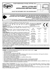
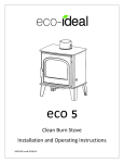
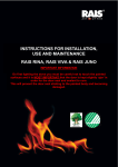
The diagrams on page 11 show the
dimensions of the approved enclosure
arrangement.
Enclosure Details (all dimensions in millimetres)
Internal heat shield
All panels including heat shield to
be produced from 30mm Skamol
Super Isol board
Internal heat shield
N.B. Ventilation openings are identical
on both sides of the enclosure.
11
RE-ASSEMBLING THE STOVE
1. Smear a bead of fire cement around
the flue hole on the outside of the
firebox.
Fire Cement
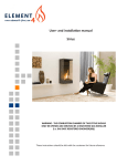
10. Unpack the Flue Baffle and identify
the two halves –
Left Hand Baffle
Right Hand Baffle
2. Offer the firebox into position and
slide it back as far as possible.
3. Refit the fixing screws through the
firebox legs. Tighten the screws
equally to draw the firebox into place.
Do not over-tighten!
4. Refit the two M8 x 25mm studs into
the two fixing holes around the flue
outlet. Fix in place with the washers
and nuts.
5. Wipe off any excess fire cement
around the inside of the flue which
may have been squeezed out when
fitting the firebox.
Wipe off excess
fire cement
6. Refit the fire bricks and log retainer.
7. Check that the valves are in the fully
open position (fully clockwise) and
refit the Air Valve Cassette.
8. Close the stove door and check that
the touch latch pin is in line with the
touch latch in the control fascia.
9. Refit the two fixing screws through
the holes in the Air valve cassette
fascia.
12
11. Stack the two baffle halves with the
right hand baffle sat on top of the left
hand baffle as shown –
12. Lift the two baffles up together inside
the firebox to the right hand side of
the baffle support bracket, slide the
baffles to the left and rest them on
the support bracket at the front of the
stove and the Tertiary Air Bar.
Support Bracket
Tertiary Air Bar
2. Slide the frame into position, making
sure that the lower inner edge of the
frame is in line with the base of the
stove, and tighten the nuts with a
10mm spanner.
13. Slide the Left hand baffle to the left and the
right hand baffle to the right, push them
towards the rear of the firebox so that the
baffles drop down and sit tightly together as
shown 3. Place a round spacer (supplied with
the frame pack) over each of the
fascia studs.
FITTING THE FRAME PACK
1. Loosen the four M6 Nuts to the ends of the
studs on the convection chamber sides.
13
4. Offer the door fascia into position,
passing the five M6 studs through the
holes. Ensure that the fascia is resting
on the two clips at the top of the door
and fix in position using the nuts and
washers provided.
Fascia resting
on clips
5. Close the door and check that there is an even
gap between the frame and door fascia on the
left and right-hand sides (approximately
16mm). Adjust as Necessary.
COMMISSIONING
Upon completion of the installation allow a
suitable period of time for any fire cement
and mortar to dry out. A small fire may then
be lit and the installation checked to ensure
the smoke and fumes are drawn up the flue
and emitted safely to atmosphere. The stove
should not be run at full output for at least 24
hours. Read the Operating Instructions
before lighting the stove for the first time.
Operating Instructions
Read the ‘General Guidance’ Section at the
start of these instructions before operating
your stove for the first time.
IMPORTANT! - Do not hang pictures,
televisions or combustible ornaments above
the stove, as these could be damaged and
could potentially create a fire hazard (For
more information read the ‘Clearance to
Combustible Materials’ section of the
installation instructions on page 7).
WARNING! – This appliance will be hot when
in operation and due care should be taken.
The supplied operating tool or gloves may be
used to open the door and operate the air
controls.
THE CLEAN AIR ACT 1993 AND SMOKE CONTROL
AREAS
Under the Clean Air Act 1993 local authorities
may declare the whole or part of the district
of the authority to be a smoke control area. It
is an offence to emit smoke from a chimney of
a building, from a furnace or from any fixed
boiler if located in a designated smoke control
area. It is also an offence to acquire an
"unauthorized fuel" for use within a smoke
control area unless it is used in an "exempt"
appliance ("exempted" from the controls
which generally apply in the smoke control
area).
The Secretary of State for Environment, Food
and Rural Affairs has powers under the Act to
authorize smokeless fuels or exempt
appliances for use in smoke control areas in
England. In Scotland and Wales this power
rests with Ministers in the devolved
administrations for those countries. Separate
legislation, the Clean Air (Northern Ireland)
Order 1981, applies in Northern Ireland.
Therefore it is a requirement that fuels burnt
14
or obtained for use in smoke control areas
have been "authorized" in Regulations and
that appliances used to burn solid fuel in
those areas (other than "authorized" fuels)
have been exempted by an Order made and
signed by the Secretary of State or Minister in
the devolved administrations.
To prevent excess smoke emissions, the air
controls of this appliance must only be
operated as directed in the instructions.
Further information on the requirements of
the Clean Air Act can be found here:
http://smokecontrol.defra.gov.uk/
Your local authority is responsible for
implementing the Clean Air Act 1993 including
designation and supervision of smoke control
areas and you can contact them for details of
Clean Air Act requirements.
The Di Lusso R6 has been recommended as
suitable for use in Smoke Control Areas when
burning wood logs.
RECOMMENDED FUEL
This appliance is designed and approved to
burn wood logs with a moisture content not
exceeding 20%. The maximum recommended
log length is 250mm (10”).
Burn only dry, well-seasoned wood, which
should have been cut, split and stacked for at
least 12 months, with free air movement
around the sides of the stack to enable it to
dry out. Burning wet or unseasoned wood will
create tar deposits in the stove and chimney,
increase harmful emissions and will not
produce a satisfactory heat output.
Do not burn waste, mineral fuel, or treated
or painted wood in this appliance.
AIR CONTROLS
Installed and used correctly this stove will
burn cleanly and efficiently. Therefore, to
avoid the disappointment of poor
performance or dirty glass, please familiarize
yourself with the controls and their
recommended settings before use.
15
To access the air controls press on the door
handle to release it from the latch and swing
it to the right.
If the door handle is swung past the point
where resistance is felt the door will be
unlatched and may swing open.
When the stove is hot the door handle can be
released by pressing the end of the operating
tool against the arm below the handle. This
will prevent damage to the paint.
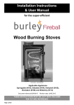
Alternatively a glove can be used.
Ignition Air Control
Combustion Air Control
Ignition Air control – regulates air flow
directly into the firebed. This is used when
lighting from cold or when reviving a fire that
has nearly burnt out. Turn clockwise to open
and anti- clockwise to close. The Ignition Air
Control must be closed once the fire is
established.
Combustion Air Control – regulates the flow
of air downwards into the combustion
chamber via the airwash (airflow over the
inside of the glass) and the air inlet at the
back of the firebox (below the tertiary air inlet
– see below). Turn clockwise to open and anticlockwise to close. This control is used to
regulate the burn rate and therefore heat
output of the stove.
Tertiary Air – Tertiary Air enters the firebox
through the series of holes in the rear wall.
This air supply helps to reduce emissions into
the atmosphere. The tertiary air supply is
fixed and cannot be adjusted.
LIGHTING
We recommend that you have two or three
small fires before you operate your stove to
its maximum heat output. This is to allow the
paint to cure in steadily and to give a long
service life to the paint finish. During this
curing in process you may notice an
unpleasant smell. It is non-toxic, but for your
comfort we would suggest that during this
period you leave all doors and windows
open.
To light the fire, load the firebox with starting
fuel, i.e. paper, dry sticks and/or firelighters.
Fully open both air controls (clockwise) and
light the fire at the base.
Once the fire is established close the Ignition
Air Control (anti-clockwise) and add more fuel
as necessary. The Combustion Air control can
now be used to regulate the burn rate of the
stove.
When the stove is up to operating
temperature the operating tool or gloves
should be used to operate the air controls.
16
RECOMMENDED SETTINGS
Once the fire is established the Ignition Air
Control should be fully closed and the
Combustion Air Control turned to a setting of
approximately 40 -50% open. This setting
should allow the nominal output and
efficiency to be achieved.
Avoid running the stove on very low air
settings as this could result in a reduction in
efficiency and increase emissions into the
atmosphere.
REFUELLING
Avoid refueling on to a low firebed as this may
cause excessive smoke emission. Ensure there
are sufficient embers to ignite the new fuel
load rapidly. Alternatively add some more
kindling before adding larger pieces of
firewood.
Do not add firewood above the level of the
tertiary air inlet at the back of the stove.
Exceeding this amount can result in the
production of excessive smoke.
DE-ASHING
From time to time it will be necessary to
remove excess ash from the firebox. This can
be done by lifting up the right hand side of the
log retainer and swinging it to the left. Ash
can then be removed with a small shovel.
Maintenance
Important! –In order to ensure continued
compliance with current Building
Regulations, Local Authority Byelaws and the
Clean Air Act (if applicable), this appliance
requires regular maintenance of the
following –
Glass Panel- clean the glass panel when cool
with a proprietary stove glass cleaner. Highly
abrasive substances should be avoided as
these can scratch the glass and make
subsequent cleaning more difficult.
Rope – If the rope is in poor condition a
replacement rope kit may be ordered from
the Di Lusso spares range.
COMPONENT REMOVAL
ANNUAL MAINTENANCE
Baffle – the removal procedure is a reversal of
the fitting procedure outlined on page 12.
Annual maintenance of the following should
be carried out by a competent person –
Air Valve Cassette – the removal procedure is
shown on page 5.
Chimney and flueways – it is important that
the chimney, flueways and any connecting
pipe are swept regularly. This means at least
twice a year for Woodburning appliances.
Only wire-centered sweeps’ brushes fitted
with a guide wheel should be used. If it is not
possible to sweep all parts of the chimney
through the appliance, ensure there is
adequate access to cleaning doors.
Side firebricks – remove the baffle and lift the
side bricks away from the base and remove.
Rear Firebricks – After removing the side
firebricks, swing the base of the upper rear
brick towards the front of the stove. Repeat
with the lower rear brick to remove it from
under the ignition air bar.
MONTHLY MAINTENANCE
Baffle – this should be removed and cleaned
at least once a month to prevent any buildup
of soot or ash that could lead to blocked
flueways.
Firebricks – in normal use these can last for
many years. It is possible, however, to
damage them if care is not taken when
refueling the stove. Check periodically for
seriously cracked bricks, which can be
replaced with new, available from your
dealer.
Air Valve Cassette – this should be removed
and cleaned monthly to remove any ash that
may be in the controls. N.B. Make sure that
the controls are in the maximum position
(turned fully clockwise) before removing the
air valve cassette.
17
If the stove is fitted in place of an open fire
the chimney should be swept one month after
installation to clear any soot falls which may
have occurred due to the difference in
combustion between the stove and the open
fire.
PERIODS OF PROLONGED NON-USE
If the stove is to be left unused for a
prolonged period, then it should be given a
thorough clean to remove ash and unburned
fuel residues. To enable a good flow of air
through the appliance to reduce condensation
and subsequent damage, leave the air
controls fully open.
If the appliance has been unused for a long
period such as during the spring and summer
months, a competent person should check the
chimney for potential obstructions before
lighting the stove i.e. get the chimney swept
before the start of the heating season.
AS NECESSARY
Stove Body – the stove is finished with a heat
resistant paint and this can be cleaned with a
soft brush. Do not clean the stove whilst it is
hot; wait until it has cooled down. The finish
can be renovated with proprietary stove
paint.
Door Catch – Over time the rope seal in the
door will become compressed. It may
therefore be necessary to adjust the door
catch to maintain the door seal. To adjust the
catch slacken the two set screws (circled
below) on the catch bar and adjust the
position of the catch bar as necessary.
Air Valves – Over time the sealing face of the
air valves may wear. This will reduce the
effectiveness of the controls. To replace a
worn valve remove the air valve cassette, lift
off the worn valve and replace with new.
Trouble shooting
Fire will not burn
Check that –
•
•
•
•
•
•
Fire blazing out of control
Check that –
•
•
•
•
•
•
•
18
The air inlet slots in the front of the
stove are not obstructed in any way.
Chimneys and flueways are clear.
A suitable fuel is being used.
There is an adequate air supply into
the room.
An extractor fan is not fitted in the
same room as the stove.
Flue draught is above minimum level
(see installation instructions).
The door is tightly closed
The air controls are in the closed
position.
A suitable fuel is being used.
The glass is not loose.
The door rope seal is in good
condition.
The air valve sealing faces are not
worn.
Flue draught is below maximum level
(see installation instructions).
19
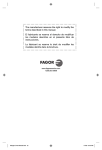
Body Spares
20
Door Spares
21
Valve Spares