1
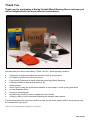
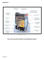
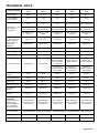
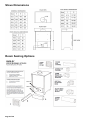
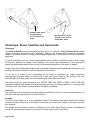
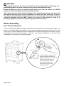
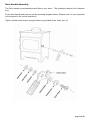
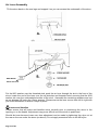
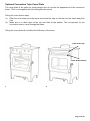
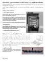
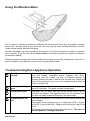
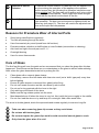
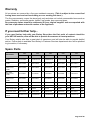
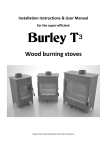
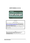
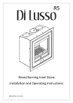
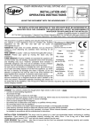
Installation Instructions
& User Manual
for the super-efficient
Wood Burning Stoves
Cross Section – Artist Impression
Applicable Appliances
Springdale (9103), Debdale (9104), Hollywell (9105),
Brampton (9108) and Wakerley (9112)
Document reference BUR/06/15
Revision date: JUNE 2015
THESE INSTRUCTIONS MUST BE LEFT WITH THE USER
FOR FUTURE REFERENCE
Page 1 of 20
Table of Contents
TECHNICAL DATA ......................................................................................................................... 5
Stove Dimensions ............................................................................................................................ 6
Room Sealing Options ..................................................................................................................... 6
Installation Instructions .................................................................................................................... 7
Approvals ......................................................................................................................................... 7
Chimneys, Flues, Hearths and Surrounds ....................................................................................... 8
Air Supply and Room Sealing Kit ..................................................................................................... 9
STOVE ASSEMBLY ...................................................................................................................... 10
Door Handle Adjustment ................................................................................................................ 10
Door Handle Assembly .................................................................................................................. 11
Air Lever Assembly ........................................................................................................................ 12
Optional Convection Tube Cover Plate .......................................................................................... 13
Assembly and Installation of the Stove Fire Bricks and Baffle ....................................................... 14
Fitting of Stove Bricks .................................................................................................................... 14
Log Retaining Bar .......................................................................................................................... 14
Commissioning the Appliance ........................................................................................................ 15
USER INSTRUCTIONS ................................................................................................................. 15
To Light the Stove .......................................................................................................................... 15
Using the Moisture Meter ............................................................................................................... 16
Troubleshooting/Poor Appliance Operation ................................................................................... 16
Reasons for Premature Wear of Internal Parts .............................................................................. 17
Care of Glass ................................................................................................................................. 17
Chimney Sweeping and Maintenance............................................................................................ 18
Safety............................................................................................................................................. 18
Warranty ........................................................................................................................................ 19
If you need further help .................................................................................................................. 19
Spare Parts .................................................................................................................................... 19
Customer & Installation Notes........................................................................................................ 20
Page 2 of 20
Thank You
Thank you for purchasing a Burley Fireball Wood Burning Stove; we hope you
will be delighted with the super-efficient performance.
Included with your stove is the Burley ‘Thank You Kit’*, which typically contains:-
·
·
·
·
·
·
·
·
·
·
A Spanner to attach and adjust the tension of the air control lever
A Coaster to protect the top of your stove
Four Hearth Protectors to place under the stove legs (Black Squares)
A Moisture Meter to ensure your wood is dry
Glass Cleaner
Stove Paint in case you prefer black handles or ever need to touch up any paint work
A Heat Resistant Glove
Scoop for removing ash
An Allen Key should you wish to adjust the door handle
A Mug to enjoy a cup of tea whilst admiring the fantastic flame picture
The contents of the kits vary from model to model, so not all the items listed or shown above may
be included with your stove.
*Thank You Kit introduced with stoves supplied from October 2013
Page 3 of 20
Features…
Cross Section – Artist Impression
You now own the world’s most efficient stove!
Page 4 of 20
TECHNICAL DATA
Springdale
9103
Debdale
9104
Hollywell
9105
Brampton
9108
Wakerley
9112
Efficiency (Net)
88.9%
89.8%
89.1%
85.5%
84.1%
CO concentration
@ 13% Oxygen
0.1%
0.1%
0.1%
0.1%
0.1%
Dry logs <20%
H₂O
Dry logs <20%
H₂O
Dry logs <20%
H₂O
Dry logs<20% H₂O
Dry logs<20% H₂O
Maximum length
170 -220mm long
Maximum length
200 -250mm long
Maximum length
250 -300mm long
Maximum length
250 -350mm lonG
Maximum length
300 -450mm long
Maximum width
150mm
Maximum width
150mm
Maximum width
150mm
Maximum width
150mm
Maximum width
150mm
Dry Logs
< 25% H₂O
Dry Logs
< 25% H₂O
Dry Logs
< 25% H₂O
Dry Logs
< 25% H₂O
Dry Logs
< 25% H₂O
220mm long
250mm long
310mm long
430mm long
580mm long
Weight in kg
45 kg
57 kg
95 kg
105 kg
130 kg
Nominal kW output
3 kW
4 kW
5 kW
8 kW
12 kW
4.1 kW
5.3 kW
6.4 kW
11.7 kW
18.3 kW
550mm sq min in
houses built after
2010, otherwise
not required
1,962mm sq min
50mm diameter
7,850mm sq min
100mm diameter
Air vent not
required if stove is
room sealed
Air vent not
required if stove is
room sealed
Air vent not
required if stove is
room sealed
All built to EN13240
Requirement of fuels
used in smoke
control areas
Lower quality fuel
can be used in nonsmoke controlled
areas, but will not
give the best
efficiencies
Max kW output
Air vent requirement.
Not Required
Not Required
Minimum flue draught
mm H²O
0.5mm
0.5mm
0.5mm
0.5mm
0.5mm
Flue gas temperature
162 °C
156 °C
122 °C
183 ˚C
237 °C
Spigot Temp.
258 °C
253 °C
241 °C
274 °C
316 °C
Flue size (Top Exit)
127mm (5”)
127mm (5”)
150mm (6”)
150mm (6”)
150mm (6”)
Min. chimney
diameter
127mm (5”)
127mm (5”)
150mm (6”)
150mm (6”)
150mm (6”)
Best chimney
diameter
127mm (5”)
127mm (5”)
150mm (6”)
150mm (6”)
175mm (7”)
20cm behind (8”)
35cm at side (14”)
35cm to Top
20cm behind (8”)
40cm at side (16”)
40cm to Top
20cm behind (8”)
35cm at side (14”)
35cm to Top
20cm behind (8”)
40cm at side (16”)
40cm to Top
20cm behind (8”)
45cm at side (18”)
45cm to Top
Minimum distance to
combustible
materials. All other
distance as per
Building regulations
Part J or HETAS
recommendations
Non combustibles
Max Hearth temp.
Min Hearth thickness
When fitted inside a masonry or similar non-flammable material recess, e.g., fireplace opening, there is no
minimum distance; although we would advise a minimum of 50mm from any surface to allow for convection.
<100 °C
<100 °C
<100 °C
<100 °C
<100 °C
12mm
12mm
12mm
12mm
12mm
Page 5 of 20
Stove Dimensions
Room Sealing Options
40mm D
50mm D
Page 6 of 20
Installation Instructions
When installing these appliances, all local regulations, including those referring to national and
European Standards need to be complied with.
This manual covers the appliances: Burley Models: 9103, 9104, 9105, 9108 and 9112
The nominal space heating output is:
‘Springdale’ 9103: 3Kw
‘Debdale’ 9104: 4Kw
‘Hollywell’ 9105: 5Kw
‘Brampton’ 9108: 8Kw
‘Wakerley’ 9112: 12Kw
Any of the above appliances should be installed by an installer registered with a competency
scheme (i.e. HETAS/ELECSA England & Wales), conforming to Building Regulations Part J and
the installation must be registered with the local council building control department.
Failure to comply with the above renders all guarantees and liabilities of the
manufacturer null and void.
By carefully following the instructions below we are certain that you will enjoy many years of
warmth and enjoyment from your new Burley Fireball Stove.
The manufacturer will not guarantee or accept liability for any problem that arises unless a local
authority building control certificate has been completed and a valid receipt or proof of purchase is
presented from the approved supplier.
The appliances should not be fitted closer to combustible materials, e.g. wooden fire surround or
stud wall, than is shown in the table on page 5.
When fitted against a wall made of combustible material e.g. a wooden stud wall with
plasterboard, unless a 75mm thick non-combustible material is used as a barrier, extra noncombustible material should be fitted behind the stove if the distance from the wall is less than
shown. When fitted inside a masonry or similar non-flammable material recess, e.g., fireplace
opening, there is no minimum distance; although we would advise a minimum of 50mm from any
surface to allow for convection.
Approvals
All our wood stoves are approved to EN13240:2001 and EN13240 A2:2004.
DEFRA Approval
The 9103, 9104, 9105 and 9108 models have been approved by DEFRA for use in smokeless
areas. They have been designed and tested with a special air plate (see below).
The plate restricts the air at high rate, but allows air into the stove when shut down to reduce the
potential for producing smoke.
Due to its huge heat output, the 9112 has not been submitted for DEFRA approval.
Web site: http://smokecontrol.defra.gov.uk/appliances.php?country=e
Page 7 of 20
Aeration hole must
be left open for
use in smokeless
areas.
Aeration hole can be
closed, if not used in
smokeless areas.
Chimneys, Flues, Hearths and Surrounds
Chimneys
The 9103 and 9104 require a minimum chimney flue of 5” (125mm), 9105, 9108 and 9112 models
require a minimum chimney flue of 6” diameter (150mm). All chimneys/flues must be a minimum
length of 4 metres and must comply with Building Regulations J. Never share the flue with another
appliance.
If flue and chimney are not to these specifications there could be insufficient draw to pull oxygen
through the appliance to make it burn properly. Due to the low temperature of the exiting flue
gases we recommend that the flue is lined to the diameter specified in the table on page 5.
Larger flues over 200mm particularly ones containing voids may affect appliance performance. We
specify particular size flues for efficient operation of our stoves.
If you live in a valley or are surrounded by tall trees or buildings you might experience
downdraught problems where the wind tries to stop the fumes rising up the chimney. An antidowndraught cowl might help, but anti-downdraught cowls reduce the draw.
We recommend you seek the advice of a HETAS (0845 634 5626) or NACE (01526 322 555)
registered supplier and installer before purchasing any stove or heating appliance. It may be wise
to contact your local chimney sweep before the stove is installed.
Flue Pipe
We recommend 1mm stainless steel pipe sprayed matt black. Only use vitreous enamel pipe if it is
stainless steel as mild steel can corrode over time.
Hearths
The stove must stand on a non-combustible surface. Installation standards dictate that hearths
must be at least 12mm thick, but installers must take into account the weight of the stove on such
thin material.
The hearth should extend a minimum of 225mm in front of the stove. When a stove is freestanding
the hearth should always extend a minimum of 150mm either side of the stove.
Page 8 of 20
Strength and heat resistance of the hearth.
Stoves are very heavy and most materials used for hearths crack very easily. It is impossible for
Burley to inspect each hearth or comment on every installation, so the onus is on the installer to
ensure the construction of the hearth is suitable for the application. Slate hearths can be
particularly fragile. If in any doubt we recommend sliding a piece of vermiculite or calcium silicate
insulation beneath the stove to protect it from the heat.
As guidance however:
· Do not use boxed and lipped hearths.
· Avoid marble, conglomerate or micro marble hearths.
· Rather than using one large piece of material, use sectional hearths or slabs which will move
independently and allow for expansion due to heat. Should a slab section crack it is then easier
and cheaper to replace.
· Bed hearths down on a level base, not directly on a hard surface which could be uneven.
· If necessary stand the stove on a steel or stone bed to ensure the weight is distributed.
· Do not subject the hearth to sudden impacts by dropping the stove. The stove is heavy and it is
strongly recommended that lifting is undertaken by two people.
· Use the hearth protection squares provided in your Thank You Kit.
Surrounds
Must be capable of withstanding the temperature produced by the stove and comply
with the minimum distances to combustibles.
Air Supply and Room Sealing Kit
All hydrocarbon burning appliances require an oxygen/air supply.
If the stove is to be fitted on an external wall the air supply can be taken straight from the outside
by using the room sealing kit. A 100mm diameter hole needs to be drilled in the correct place
(138mm above the hearth) to take the 86mm external (80mm internal) duct as supplied. This will
allow for easy connection. Any gap can be filled in with cement or mastic.
· A proprietary grille is supplied with the kit.
· A room sealing kit which exits horizontally is available.
The room sealing method of supplying air is always to be preferred as heat loss from the room will
be greatly reduced.
If the stove is not on an outside wall or the room sealing kit cannot be used, an air vent must be
supplied in the room in which the stove is fitted. The sizes of the vents required are:
· 3Kw – No vent required
· 4Kw - No vent required
· 5Kw – For homes built before 2010 – no vent required. For homes built after 2010 - 550mm sq
· 8Kw - 1650mm sq (50mm diameter)
· 12Kw 4950mm Sq (100mm diameter)
Only permanently open vents can be used and consideration should be given to draught when the
stove is not in use, therefore site this vent carefully. The vent covers should comply with Building
Regulations Part J and should be sited where they cannot be blocked.
Page 9 of 20
WARNING
The Burley Fireball series of stoves are primarily for burning wood (this includes logs and
sawdust briquettes). In smoke control areas only wood fuels should be used.
Before purchasing a stove we would strongly advise you seek the advice of a HETAS
installer to ensure suitability of the product to your home.
Other fuels, such as coal (any type), smokeless fuels or petroleum coke can only be used if
the optional multi-fuel grate is fitted (available on models 9104 and 9105 only). Under no
circumstances should liquid fuels be added. It is not an incinerator and rubbish, including
painted or tanalised wood and MDF, should not be burnt in this appliance, doing so is
potentially dangerous and will invalidate any guarantees immediately.
Stove Assembly
Door Handle Adjustment
There is a CAM and LOBE mechanism which allows the handle to be moved up and down or in
and out. If required, adjust the handle so it lines up and engages correctly with the stud in the side
of the stove. Incorrect alignment will put excessive force on the door hinges or will result in a poor
seal between the door and the stove. The door may require adjustment as the rope seal
compresses. A 5mm Allen key will be required.
To adjust the door, loosen off the
socket screw with the Allen key.
Holding the Allen key, use a spanner
to turn the off centre cam to
position the handle. Hold the
cam in the desired position
whilst tightening the screw
with the Allen key.
Page 10 of 20
Door Handle Assembly
The Door handle is pre-assembled and fitted to your stove. The information below is for reference
only.
Fit the door handle and parts as per the assembly diagram below. (Please note it is very important
to fit the parts in the correct sequence).
Tighten up the socket screw using the Allen key provided in the ‘thank you’ kit.
Page 11 of 20
Air Lever Assembly
Tilt the stove back on the rear legs and support it so you can access the underneath of the stove
(A).
M10 Washer
above lever arm
Put the M10 washer over the threaded stud, push the air lever through the slot in the front of the
stove, locate the end of the lever over the air plate bar and threaded stud, ensuring that the M10
washer sits over the unthreaded shoulder of the stud. Assemble the remaining washers and nut
as per diagram (B) using the 13mm spanner. Please ensure the lever moves from left to right with
just a little resistance to ensure it stays in place.
Levers and Handles
Please ensure that all levers and handles move correctly prior to positioning the stove in the
opening or on the hearth. Adjustment may prove difficult once the stove is positioned.
Should the lever become loose over time adjustment can be made by tightening the nyloc nut at
the rear or the one under the stove (as above). Do not apply excessive force to the M8 nyloc
Page 12 of 20
Optional Convection Tube Cover Plate
The cover plate is an option for those people who do not like the appearance of the convection
tubes. (This is not supplied with the Springdale 3kw stove)
Fitting the cover plate is easy:
(1)
Offer the cover plate up to the stove and locate the clips on the rear into the tubes and push
it on.
(2.) Make sure it is fitted open at the top and flush at the bottom. This is important for the
convection heat to come through the tubes.
Fitting the cover plate will not affect the efficiency of the stove.
Open at the top
Flush at the bottom
1
2
Page 13 of 20
Assembly and Installation of the Stove Fire Bricks and Baffle
Having positioned your Burley stove and connected it to a chimney with flue pipe, you need to
assemble the inside parts.
There are five internal components: top brick, two side cheeks, a rear brick and a stainless steel
baffle.
Fitting of Stove Bricks
To fit the vermiculite bricks:
Place the left side in so the longer edge is at the front
and the shorter edge at the rear.
Put the top brick in the stove so the rounded edges are
at the back and the flat surface is up. The top brick
should stay in place by resting it on the side brick and
the top of the square metal tubes.
Place the right side in so the longer edge is at the front
Place the back in.
Slide the top brick backwards so the lip sits over the
back and side bricks, keeping them in place and
ensuring there is no gap at the back.
The base brick should already be fitted.
Fitting the Stainless Steel Baffle Plate
Fit the plate by putting the legs of the plate on top of the rear
square metal tubes, you may need to lift the top brick. Bring the
plate forward so it sits on the ledge above the door. Check that
the top brick is still at the back of the stove and has not moved
forward.
When sweeping the chimney or carrying out regular maintenance
on the stove, reverse the above procedure, clean the chimney
and the top surface of the top baffle and the stainless steel mesh,
then reposition all the components.
Log Retaining Bar
Fit the log retaining bar so the angled return
is pointing into the stove. This will help to
keep the glass clean.
Page 14 of 20
Commissioning the Appliance
On completion of the installation, when any fire cement or paint used has dried, a smoke ‘bomb’
should be burnt and all joints checked for smoke leakage and the chimney draw checked with all
doors and windows closed. Please leave the instructions with the customer and inform them;The first time the stove is lit only a small fire should be used to allow the paint to cure properly.
Ventilate the room well as the fumes can be pungent. Use a small amount of kindling to start
the fire. If possible leave the door on the catch, although the fire looks fierce it is comparatively
cool due to all the air being drawn in. Add a little more kindling as it burns down. When you have a
small bed of embers place a small split log in the fire, allow it to catch well, and then close the door
with the lever to the right. Stay with the fire during this process. When this first log is burning down
add another log, when this one is burning well you should be able to move the lever midway to the
centre. Keep feeding the stove for three hours with a small split log as it burns low.
When you need to remove some ash wait until it is cold and then take some out using the scoop
provided. Always leave an inch of ash so you have a nice bed for your next fire.
USER INSTRUCTIONS
To Light the Stove
It is important to keep an approximate minimum depth of ¾” (20mm) of wood ash in the fire box at
any time. You will achieve this after the first few firings.
Place 1 or 2 firelighters in the bottom, then add some kindling wood criss-crossed, and finally a
small log on top. Light the firelighters, open the air vent to maximum (to the right) and close the
door to the first latch so there is an air gap around it.
Leave it like this for around five minutes or so, the fire should be well alight and the door can now
be closed to become air tight. Leave the air control lever to the right for a further 10 to 20 minutes
to get the stove completely up to running temperature. If the stove does goes out when the door is
closed then the flue is still too cold and will not pull, in this case you may need to leave the door
open with kindling burning for longer. The flue’s pull will change dependant on temperature and
atmospheric conditions.
The best lever position to achieve maximum efficiency will depend on the chimney draw, but will
normally be near the centre. Every chimney is different, and you will eventually find your stove’s
optimum position. This is when the flames are swirling in a lazy manner around the stove, not
roaring. If the lever is pushed too far to the left, you starve the fire of oxygen, causing the glass to
darken. Move the lever a small amount to the right until the glass just stays clean. We do not
recommend use of a stove thermometer – the high efficiency of the stove means flue gases are
cool and would give an inaccurate reading, leading to over firing and damage to internal
components.
The best way to run any wood stove is ‘little and often’. If you are with the fire, it is best to keep
adding a small log every 45 minutes rather than adding large ones every 2 hours.
THE STOVE IS NOT DESIGNED TO BE USED WITH THE DOOR OPEN!
To reload, open the door slowly to allow the pressure to equalise. Using the glove provided, place
the fresh log towards the rear of the appliance. Close the door.
Do not over load the stove with wood and close the damper down, this produces lots of
creosote and blackens the glass
Page 15 of 20
Using the Moisture Meter
For the stove to operate at maximum efficiency the wood should be as dry as possible, certainly
below 18%. Burning damp or wet wood will not only stop the stove working efficiently, but also
create excess smoke and stain the glass.
Remove the plastic cap covering the two contact pins. The pins are sharp for a reason, so please
use it carefully. Push the pins into the inner surface of the split log (5mm as a guide) this will give
an accurate reading.
Simply putting the contact pins onto the surface will not give an accurate reading, as it may tell you
that the surface is dry whilst the interior of the log may well be damp.
Troubleshooting/Poor Appliance Operation
Refuelling onto a low
fire bed
If there is insufficient burning material in the fire bed to light a
new fuel charge, excessive smoke emission can occur.
Refuelling must be carried out onto a sufficient quantity of
glowing embers and ash to ensure that the new fuel charge will
ignite. If the fuel bed is too low or cool, suitable kindling must be
used to re-light fires.
Air damper left fully
open
Although the fire will look impressive, you will be burning more
wood for less heat. The glass can also be damaged.
Leaving door open
Operation with the door open can cause excess smoke and a
potential fire hazard. The appliance must not be operated with
the door left open except as directed in the instructions.
Overloading the fire
bed
The maximum amount of fuel specified in this manual should not
be exceeded.
The weight of dry wood per hour is: 1.0kg for the 9103, 1.3kg for
the 9104, 1.6kg for the 9105, 2.8kg for the 9108 and 4.4kg for the
9112.
Overloading can damage components of the stove. The stove is
not designed for overnight operation.
Page 16 of 20
Substantial Smoke
Emission
If substantial smoke emission is observed from the appliance at
any time during the operation of the appliance the operator
should ensure they are following the operation instructions and
using suitable fuel. The flue may not be pulling as it is too cold or
incorrectly specified/installed. There might be a down draught.
Check that the top brick is at the back of the fire.
Door Adjustment
The locking mechanism on the door is made up of a cam and
lobe assembly. The door can be loosened or tightened with an
Allen key (see page 10). The door will need to be adjusted over
time as the rope seal compresses.
Reasons for Premature Wear of Internal Parts
·
·
·
·
·
·
·
Stove being used/fired too vigorously
Too little air passing through the stove
Use of excessively dry wood (wood from old furniture)
Excessive debris collection on baffle plate or inner fireback (see section on cleaning)
Ash level too high in the ash pan over 2 ½ “
Overnight burning
Use of a stove thermometer
Care of Glass
The first few firings will cure the paint and we recommend that you clean the glass after this has
happened. This will ensure that there are no contaminates on the glass to attract further staining.
After a time the glass does deteriorate but to prolong the life:
·
·
·
·
·
·
·
·
·
Clean glass with a ceramic glass cleaner
If necessary, remove fired on stains with clean wire wool (not a ‘brillo’ type pad) every time
before lighting
Ensure all glass cleaner is removed from glass before firing
Do not over aerate the stove as this can cause fly ash to stick.
Do not run for long periods with the lever to the right
Only add logs at the back of the stove
Make sure the log retainer points into the stove
Most deposits burn off when the stove is very hot, this is with the lever roughly in the middle
Do not over load the stove or try and keep it in overnight. Add a little wood often.
The stove is double glazed; check the rope seals and screws regularly to ensure a long life.
Take care when removing glass clip screws or they could shear
Do not use with broken glass
Do not over tighten the glass clips as this could cause the internal glass to crack.
Only clean the glass when it is cold.
Page 17 of 20
Chimney Sweeping and Maintenance
It may be wise to contact your local chimney sweep before the stove is installed. Your chimney
should be swept at least once a year by a registered sweep, twice a year with heavy use. The
sweep should also replace the fire cement at the base of the flue if necessary.
·
·
·
·
·
The chimney can be swept through the stove.
The stainless steel baffle and top brick should be removed in the reverse order described
on page 14.
The baffle should be cleaned at least twice a year with heavy use, checked, renewed as
required and replaced.
Unless advised by Burley the stove should not be used with any baffle missing.
All rope and glass seals should be checked annually and replaced as necessary.
If the stove has not been used for a prolonged period, in excess of 6 months, the chimney should
be swept prior to use to check for blockages, birds’ nests etc. and rubble/debris blocking the flue
ways.
Safety
NOTE: As with all solid fuel appliances, a carbon monoxide detector should be
purchased for use in the room. All solid fuel appliances produce considerably more
Carbon Monoxide in normal use than oil or gas appliances, but the general ‘smell’ of the
smoke or exhaust is much stronger and more easily detected by a healthy person.
·
Always use your appliance with the door shut and look for tell-tale signs of excessive
leakage: smoke stains above the fireplace, smoke emitting around the door when running,
strong smell of soot upstairs etc.
·
Check the seals at the joints annually and replace the fire cement as required. Check
especially the joint of the flue pipe to the chimney register plate, hairline cracks are OK, but
lumps of cement missing produce a bad joint. A proprietary jointing compound should be
used here, as it is far superior to a cement and rope seal.
·
Never block air vents either internally or externally.
·
Use the supplied glove to reload the stove.
·
In the event of a chimney fire, close the door and shut the air vent right down. If possible
throw ½ cup of course table salt onto the fire.
·
Never modify parts or fit parts to the appliance that are not recommended by the
manufacturer.
·
Never use this appliance in the same flue as another appliance.
·
The surface of a wood burning stove gets extremely hot in normal use. When using the stove
in situations where children or aged and/or infirm persons are present, a fireguard must be
used to prevent accidental contact with the stove. The fireguard should be manufactured in
accordance with BS 8423:2002.
Page 18 of 20
Warranty
All our stoves are covered by a five year metalwork warranty. (This is subject to the correct fuel
having been used and not overloading or over aerating the stove.)
The five year warranty covers the stove body only and does not include consumable items such as
grates, firebricks, vermiculite panels, baffles, log guards, door rope and glass.
Any warranty claims should be addressed to your original supplier and accompanied with
the date of purchase and serial number of the appliance.
If you need further help…
If you need further help with your Burley Stove then the first point of contact should be
your HETAS installer, who will be able to provide the answers to most questions.
Your Burley retailer also has a great deal of experience and will also be able to provide helpful
advice. Further help is available from Burley’s Customer Services department who will be pleased
to give advice, if necessary.
Spare Parts
9103
9104
9105
9108
9112
DESCRIPTION
PART NO
QTY
PART NO
QTY
PART NO
QTY
PART NO
QTY
PART NO
QTY
TOP VERMICULITE
BOARD
WTOPLINER3
1
WTOPBAFFLE4
1
WTOPBAFFLE5
1
WTOPBAFFLE8
1
WTOPBAFFLE12
1
BACK VERMICULITE
BOARD
WBACLINER3
1
WBACLINER4
1
WBACLINER5
1
WBACLINER8
1
WBACLINER12
1
BOTTOM
VERMICULITE
BOARD
WBOTLINER3
1
WBOTLINER4
1
WBOTLINER5
1
WBOTLINER8
1
WBOTLINER12
1
LEFT HAND
VERMICULITE
BOARD
WL/HLINER3
1
WL/HLINER4
1
WL/HLINER5
1
WL/HLINER8
1
WL/HLINER12
1
RIGHT HAND
VERMICULITE
BOARD
WR/HLINER3
1
WR/HLINER4
1
WR/HLINER5
1
WR/HLINER8
1
WR/HLINER12
1
GLASS
WGLASS/3
2
WGLASS/MIC
2
WGLASS/S
2
WGLASSM
2
WGLASSL
2
GLASS CLIPS
WGLASSCLIP/M
2
WGLASSCLIP/M
2
WGLASSCLIP/S
2
WGLASSCLIP/S
2
WGLASSCLIP/L
2
GLASS ROPE TAPE
WROPE
1M WROPE
1M WROPE
1M WROPE
2M WROPE
3M
DOOR SEAL ROPE
WSEALROPE
1M WSEALROPE
1M WSEALROPE
1M WSEALROPE
2M WSEALROPE
3M
STAINLESS STEEL
BAFFLE
WLOWBAF9103
1
WLOWBAFMIC
1
WLOWBAFSMA
1
WLOWBAFMED
1
WLOWBAFLAR
1
Page 19 of 20
Customer & Installation Notes
Date of Installation:
Installer Name & contact details
Chimney Swept
Date
Notes:
Made in the UK
Burley Appliances Limited
Lands’ End Way
Oakham
Rutland
LE15 6RB
United Kingdom
Page 20 of 20
Further information can be found at:
burley.co.uk/woodburner.php
Email: [email protected]
Phone: 01572 756956
Fax:
01572 724390