1
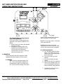
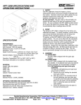
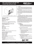
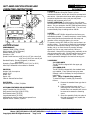
MPT-500B SPECIFICATIONS AND
OPERATING INSTRUCTIONS
ZERO
RESET
500LB MAX CAPACITY
MOTOR CONTROL
IN HI
OUT LO
6
1
RATE OF PULL
7
8
9
2
3
4
10
5
SPECIFICATIONS
PERFORMANCE
Capacity: 500lb (227Kg) (2224N)
Safe Overload: 150% of capacity
Readout Accuracy: ±0.5%
Resolution: 0.2lb
Speed Control Accuracy:±1/8”/min @ 1-5”/min rate of pull
±1/4”/min @ 6-10”/min rate of pull
Standard Display: Pounds, Kilograms, or Newtons
Units (XXX.X)
Operating Temperature: 50°F to 100°F (10°C to 38°C)
Auto-Stop: Selectable to be enabled or disabled
PHYSICAL
Weight: 26lb, less options
Height: 8.5in
Width: 10in
Depth: 15in
Cabinet: Painted Carbon Steel
ELECTRICAL
Standard Power: 115VAC, 50/60Hz
OPTIONAL FEATURES AND ACCESSORIES
Large T-Handle Grip (P/N 15-3271)
Ring terminal lower grip (P/N 15-3276)
Small slotted wheel (15-3275)
Large slotted wheel (15-3278)
Adjustable set point for motor stop at preset force
Optional Power: 230VAC, 50/60Hz
DATASHEET___
1. SAFETY
The MPT-500B Wire Crimp Pull Tester is a force
measurement device, and as such should be operated with
due caution. Operators should wear safety glasses for eye
protection because the crimp under test may break
suddenly and fragments may fly off.
DO NOT OVERLOAD: The gear motor in the pull tester
can exceed the load limits of the load cell component in this
device. For your protection the MPT-500B has been factory
set to stop if the peak force exceeds 500lb. The unit is set
to automatically stop at readings above 499.9lb.
2. SETUP
The Alphatron MPT-500B is shipped from the factory precalibrated and tested. To assure consistent, correct results,
users should familiarize themselves with the setup and
operation of the unit before placing it in service.
To operate, set the MPT-500B on a flat, level surface in an
upright position. The unit can be tilted with the adjustable
front feet to ease operator viewing of the display. Do not
handle, pick up or move the unit by exerting leverage
against any front or rear panel controls, fixtures or
connections. Always lift by the base plate, preferably at the
mid-point along either side. DO NOT use the lower grip as
a handle for lifting or moving the MPT-500B. This can
result in permanent damage to the load cell sensing unit.
3. ASSEMBLY
3.1 UPPER GRIP
The MPT-500B is shipped with the upper grip
installed.
3.2 LOWER GRIP
The MPT-500B is shipped with the standard lower
grip installed. If any optional lower grips were
ordered, it will be necessary for the purchaser to
install them.
3.2.1 Large T-Handle Grip (optional)
To install the large T-handle grip proceed as
follows:
A. Remove the standard lower grip that is
in place.
B. Place the mounting screw in the
mounting hole of the load cell. The Thandle sleeve nut assembly will have to
be removed to access the mounting
screw.
C. Screw the assembly firmly into place in
the load cell sensing unit, replace the
T-handle assembly.
______________________________________________________________________
Daniels Manufacturing Corporation, 526 Thorpe Road, Orlando, FL 32824, U.S.A.
Phone: (407) 855-6161 • Fax (407) 855-6884 • www.dmctools.com • Email: [email protected]
Revision B
02/07
MPT-500B-DS
Copyright©2005 All Rights Reserved
Page 1 of 6
MPT-500B SPECIFICATIONS AND
OPERATING INSTRUCTIONS
ZERO
DATASHEET___
RESET
500LB MAX CAPACITY
MOTOR CONTROL
IN HI 6
OUT LO 1
RATE OF PULL
7
8
9
4
2
3
10
5
3.2.2 Slotted Wheel or Ring Terminal
Lower Grips (Optional)
If the ring terminal or slotted wheel lower
grips have been ordered, installation is as
follows:
A. Remove the screw holding the standard
lower grip in place.
B. Substitute the optional grip for the
standard grip and tighten the screw
until the lower grip rotates with
resistance but is not loose or does not
need to be forced to turn.
4. OPERATION
In the instructions that follow operation of both
standard and optional features will be covered.
4.1 POWER
4.1.1 Check the operating voltage of the
unit. The correct operating voltage is on
the identification label on the back of the
unit. Be sure that this voltage is the same
as the voltage available at your location
before you plug in the MPT-500B.
4.1.2 Turn the power switch in the center
of the back plate OFF.
4.1.3 Plug the power cord into its
receptacle on the back of the MPT-500B,
and into the incoming power receptacle.
4.1.4 Startup Sequence
A. Turn the power switch ON (Rear
Panel). The display will turn on
and the motor control stop switch
will be illuminated.
B. The unit will warm up for 60
seconds.
C. The unit will display the serial
number.
D. Unit zero will need to be adjusted.
E. When the unit displays 000.0, the
unit will automatically perform an
internal calibration test sequence.
F. If calibration is OK the unit will
then go into test mode.
______________________________________________________________________
Daniels Manufacturing Corporation, 526 Thorpe Road, Orlando, FL 32824, U.S.A.
Phone: (407) 855-6161 • Fax (407) 855-6884 • www.dmctools.com • Email: [email protected]
Revision B
02/07
MPT-500B-DS
Copyright©2005 All Rights Reserved
Page 2 of 6
MPT-500B SPECIFICATIONS AND
OPERATING INSTRUCTIONS
G. If calibration is not OK an error will
be displayed and you will need to
contact DMC.
NOTE: The above sequence is only performed at
startup, not after each test. After each test the
Upper grip, and display reset, and the unit is then
ready to test again.
4.2 LOWER GRIP
4.2.1 (Optional Grip) Rotate the lower grip
to place the correct slot or stud for the
wire/terminal under test in the uppermost
position. Select a slot that is the same
width as the wire diameter, or one size
larger. Select a stud that the ring terminal
just goes over.
4.2.2 Self Tightening Cam Type Lower Grip
(Standard). Depress the operating lever of
the self tightening cam type lower grip to
open it far enough to accept the sample
under test. When you release the lever,
the cam wheels will grip the sample.
NOTE: DO NOT POSITION THE GRIP
PRESSURE ONTO THE CRIMP BARREL OF
THE TEST SAMPLE.
4.3 UPPER GRIP
4.3.1 If the upper grip is not positioned in
the home position, as shown in the diagram
on page 2, press the RESET button.
4.3.2 Depress the operating lever of the
self tightening cam type upper grip to open
far enough to accept the test sample
(wire). When you release the lever, the
cam wheel will grip the wire.
4.4 FRONT PANEL CONTROLS
4.4.1 MOTOR CONTROLS
NOTE: PRESS AND HOLD SWITCHES
FOR APPROXIMATELY 1 SECOND TO
ALLOW FOR PROPER ACTIVATION
START-Motor start switch to begin test.
RESET-resets display meter to zero, and
resets pull wheel to START position for the
next test. Reset must be performed after
each test.
DATASHEET___
4.4.2 RATE OF PULL CONTROLS
LO-HI SWITCH
LO (Green)-selects rate of pull of 1-5
in/min.
HI (Yellow)-selects rate of pull of 6-10
in/min.
NUMBERED RATE SWITCHES
Select the rate of pull, 1-5 in/min (LOGreen), or 6-10 in/min (HI-Yellow) as
chosen by setting of LO-HI switch.
4.4.3 DISPLAY CONTROLS
ZERO – Adjusts the display to true zero.
When turned counterclockwise the meter
reading will decrease. When turned
clockwise the meter reading will increase.
The display will be checked for zero
adjustments at startup and after each test
when the RESET switch is pressed.
4.5 OPTIONAL CONTROLS ON THE FRONT
PLATE
4.5.1 – The SETPOINT option enables an
operator to set the force at which the MPT500B is to stop automatically if the test
proceeds to that force and the connection
under test does not fail.
When the SETPOINT/MEASURE switch is
held in the MEASURE position it enables the
operator to select the set point by turning
the SET adjusting knob next to the switch.
As the knob is turned, the set point force
will be indicated on the display meter.
Clockwise adjustment increases the set
point value, and turning the knob
counterclockwise decreases the value. The
force reading from the load cell is disabled,
and will not be enabled until the switch is in
the SETPOINT (raised) position. Tests are
conducted with the switch in the raised
STOP- Stops the motor and the meter
retains the current peak value.
______________________________________________________________________
Daniels Manufacturing Corporation, 526 Thorpe Road, Orlando, FL 32824, U.S.A.
Phone: (407) 855-6161 • Fax (407) 855-6884 • www.dmctools.com • Email: [email protected]
Revision B
02/07
MPT-500B-DS
Copyright©2005 All Rights Reserved
Page 3 of 6
MPT-500B SPECIFICATIONS AND
OPERATING INSTRUCTIONS
position. When the load reaches the set
point level, the motor will stop and the unit
can be reset and reloaded for the next test.
This option can be used in conjunction with
the AUTO STOP (4.6.6) feature. When
both features are turned on, the test will
stop automatically if either condition is met
(AUTO STOP, or SETPOINT).
If the peak reading of the force necessary
to part a connection is desired, the set
point should be at 499.9lb before testing.
4.5.2 – The CONSTANT FORCE option
operates similarly to the SETPOINT option.
The difference being that when the set
point value is reached the connection is
held at that load, instead of the test
stopping. An additional switch is provided
above the SET knob. The switch should be
set to PEAK for normal operation, and to
CONTINUOUS when using the CONSTANT
FORCE option.
4.6 SPECIAL FEATURES
4.6.1 RS-232 DIGITAL OUTPUT
The MPT-500B is shipped from the factory
with RS-232 output installed. It is
configured with all required communication
parameters preset to the most common
settings.
4.6.2 RS-232 SPECIFICATIONS
Communications System:
Full Duplex
Baud Rate:
9600
Data Bits:
8
Stop Bits:
1
Parity:
None
Coding:
ASCII
4.6.3 RS-232 CONNECTION
Pin Out:
DB9
Pin 2:
(Rx) Receive
Pin 3:
(Tx) Transmit
Pin 5:
Signal Ground
4.6.4 RS-232 DATA FORMAT
Output from the RS-232 port will mirror the
messages and data displayed on the LCD
Display.
DATASHEET___
Example: System Power Up
Alphatron Warming Up
S/N# XXXXXX
Adjust Zero
Data Stream XXX.X-------------XXX.X
Calibrating
XXX.X (Random R-cal value)
Calibration OK
Test in Process
Data Stream XXX.X-------------XXX.X
Stop
4.6.5 DIP SWITCH SETTINGS
The dip switches are accessed through the
opening on the left side of the MPT-500B.
The access opening is covered with a plate
that can be swung out of the way. Turn
the large captivated screw counter
clockwise until it comes loose from the side
cover. The label below the cover depicts
the switch banks and lists the switch
functions. The detailed description of the
switch settings is as follows:
Bank SW1 (Toward rear of tester)
Switch 1:
Not Used
Switch 2:
Not Used
Switch 3:
Not Used
Switch 4:
Not Used
Switch 5: Factory Setting DO NOT adjust.
Switch 6: Factory Setting DO NOT adjust.
Switch 7: Auto Stop
Down=Off
Up=On
Bank SW2 (Toward front of tester)
Switch 1:
Switch 2:
Not Used
lb units
Down
______________________________________________________________________
Daniels Manufacturing Corporation, 526 Thorpe Road, Orlando, FL 32824, U.S.A.
Phone: (407) 855-6161 • Fax (407) 855-6884 • www.dmctools.com • Email: [email protected]
Revision B
02/07
MPT-500B-DS
Copyright©2005 All Rights Reserved
Page 4 of 6
MPT-500B SPECIFICATIONS AND
OPERATING INSTRUCTIONS
(Section 4.7)
Kg units
Up
N units
Up
Switch 3:
(Section 4.7)
lb units
Kg units
N units
Up
Down
Up
Switch 4:
Continuous
Peak
Up
Down
Switch 5: Factory Setting DO NOT adjust.
Switch 6: Factory Setting DO NOT adjust.
Switch 7: Factory Setting DO NOT adjust.
NOTE: Switches 5, 6, & 7 are factory
settings. Do not change from positions
shown.
NOTE: The unit must be turned off, and
then back on for dip switch changes to take
effect.
4.6.6 AUTO STOP
This feature stops the pull test when the
piece under test fails. When the force
applied to the piece drops below 70% of
the displayed reading, the test is completed
and the unit stops. This feature is turned
on or off using switch 7 of dip switch bank
SW1.
ON=AUTO STOP works.
OFF=AUTO STOP disabled (the STOP
switch must be used at the completion of a
test).
NOTE: The AUTOSTOP function will not
operate if the test range is at or below
approximately 1.5lb. This is necessary to
allow for the preload that an operator will
normally apply when inserting a connector
for the test. If the preload is greater than
the lower limit, the unit will not start. In
this case depress the reset toggle switch
next to the display to be able to begin test.
DATASHEET___
4.7 POUND, KILOGRAM NEWTON
SWITCHING
Dip switch 2 & 3 control the type of units
that are measured by the tester. If pounds
are desired switch 2 is down and switch 3 is
up. If kilograms are desired switch 2 is up
and switch 3 is down. If Newton units are
desired both switch 2 and 3 are up. Cycle
the units power off and back after changing
any of these settings.
4.8 FUSE
If the main fuse requires replacement
install a .3 Amp 125/250V slow blow fuse.
The fuse compartment is located on the
back of the unit and labeled as FUSE.
4.9 CALIBRATION
The MPT-500B wire crimp pull tester is
factory calibrated with equipment traceable
to the NIST. It is recommended practice to
return the unit to DMC for calibration. In
order to maintain traceability to NIST, do
not exceed 12 months between factory
calibration intervals.
The internal calibration test sequence is a
reliable verification that the tester is
accurate, but it does not assure traceability
to NIST.
______________________________________________________________________
Daniels Manufacturing Corporation, 526 Thorpe Road, Orlando, FL 32824, U.S.A.
Phone: (407) 855-6161 • Fax (407) 855-6884 • www.dmctools.com • Email: [email protected]
Revision B
02/07
MPT-500B-DS
Copyright©2005 All Rights Reserved
Page 5 of 6
MPT-500B SPECIFICATIONS AND
OPERATING INSTRUCTIONS
DATASHEET___
LIMITATION OF LIABILITY/LIMITED
WARRANTY*
DANIELS MANUFACTURING CORPORATION
IS NOT LIABLE FOR CONSEQUENTIAL OR
SPECIAL DAMAGES OF ANY NATURE OR
KIND RESULTING FROM THE USE OF ANY
OF ITS PRODUCTS. OWNERS AND USERS
OF DMC PRODUCTS ASSUME FULL
RESPONSIBILTY FOR INSTRUCTING THEIR
EMPLOYEES IN THE PROPER AND SAFE
USE OF SUCH PRODUCTS.
Daniels Manufacturing Corporation warrants
each new unit sold by it to be free from
defects in material and workmanship under
normal use and service. Its obligation
under this warranty is limited to the free
correction or, at its option, the refund of
the purchase price of any such unit which
proves defective within ninety (90) days
after delivery to the first user, provided that
the unit is returned with all transportation
charges prepaid, and which shall appear to
its satisfaction, upon inspection by it, to
have been defective in material or
workmanship. This warranty shall not
cover any damage to such products, which
in the opinion of Daniels Manufacturing
Corporation, was caused by normal wear,
misuse, improper operation or accident.
This warranty is in lieu of all other
warranties express or implied. No
warranty, express or implied, is made or
authorized to be made or assumed with
respect to products of Daniels
Manufacturing Corporation, other than that
herein set forth.
*as defined by PL93-637
______________________________________________________________________
Daniels Manufacturing Corporation, 526 Thorpe Road, Orlando, FL 32824, U.S.A.
Phone: (407) 855-6161 • Fax (407) 855-6884 • www.dmctools.com • Email: [email protected]
Revision B
02/07
MPT-500B-DS
Copyright©2005 All Rights Reserved
Page 6 of 6