1
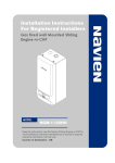
Installation and Operating Instructions
Amber Switch Type CAS-I-B
1
Introduction
2
Amber Switch is an automatic, electronic, frequency-sensing,
operating control. It can be applied to small islanded power systems
with renewable generation which produce a variable frequency, some
inverters for example.
Amber Switch can switch on additional loads for surplus renewable
generation which might otherwise be wasted. Amber Switch
determines this surplus generation by detecting a rise in the system
frequency. This may be caused by low load on a generator with
frequency droop, or an increase in frequency from battery inverters to
signal a high state of battery charge.
Amber Switch incorporates a number of features to help ensure stable
operation of an islanded power system:
•
•
•
•
A range of switch-on setting frequencies are available to create a
prioritised system
The switch-off frequency is lower than the switch-on frequency to
avoid constant switching and provide stability.
When the frequency goes above the switch-on setting there is a
delay before the load is connected, with a higher frequency
causing a shorter delay. A similar delay applies at switch-off for
low frequencies
The delays are randomised to avoid multiple devices switching
simultaneously.
Each time the Amber Switch operates, a new random time factor is
chosen, to help ensure fairness across the entire power system.
Amber Switch can control loads up to 15A (3.4kW at 230V; 1.8kW at
120V). The most appropriate loads are heaters (water heaters, storage
heaters, space heaters). Appliances with pumps are not appropriate
due to the potential for frequent switching of loads.
There are 8 selectable frequencies for the 50Hz band and 8 for the
60Hz band. For a small number of loads with equal priority, the default
setting of 51Hz may be used. For systems with many loads, different
priorities may need to be set by the system manager. For instance it
might be decided that immersion heaters are given highest priority
(lowest frequency), then portable space heaters and finally fixed space
heaters (highest frequency).
Description of Operation
Amber Switch is a completely autonomous device which requires no
user intervention. It will switch the load on when the system frequency
is high and switch it off when the frequency is low, as described in the
Introduction.
Indications
Two LEDs indicate the operating state of the device, see Table 1.
Faster flashing of the amber LED indicates a shorter time to switch,
slower flashing indicates that it will take longer to switch on.
Loss of Supply
As would be expected, any appliance or load fed through the Amber
Switch will switch off when the supply is lost. When the supply is
restored the appliance may operate for a few seconds while the Amber
Switch powers up. At that point the appliance will be switched off while
the Amber Switch assesses the supply frequency. If the frequency is
above the switch-on setting the normal switch-on delay will apply and
then the appliance will be switched on.
3
Settings
Only one user-adjustable setting is provided (switch-on frequency) and
this is only accessible during installation (see section 4). Under normal
circumstances it should not be necessary to adjust the setting once it
has been set during installation. The setting is achieved through a DIP
switch (see Figure 2).
Table 2 shows the positions for each frequency setting. In the Figure 2
example all the switches are OFF (down), representing a setting of
61.5 Hz.
DO NOT REMOVE THE COVER OR ADJUST SETTINGS UNLESS
THE AMBER SWITCH IS ISOLATED FROM THE POWER SUPPLY.
Figure 2 Setting DIPSwitch
Figure 1 Schematic Arrangement of Amber Switch
Lin
Lout
N
N
E
E
Table 2 Frequency Settings
LOAD
SUPPLY
f>
Setting
Table 1 LED states
1
2
3
4
49.75Hz ON
ON
ON
ON
50.0
ON
ON
ON OFF
50.25
ON
Setting
1
2
59.75Hz OFF ON
3
4
ON
ON
60.0
OFF ON
ON OFF
ON OFF ON
60.25
OFF ON OFF ON
ON OFF OFF
60.5
OFF ON OFF OFF
60.75
OFF OFF ON
LED state
System state
Load
50.5
ON
Amber LED steady
Frequency low
Off
50.75
ON OFF ON
Amber LED flashing
Frequency high, delay in progress
Off
51.0
ON OFF ON OFF
61.0
OFF OFF ON OFF
Green LED steady
Frequency high
On
51.25
ON OFF OFF ON
61.25
OFF OFF OFF ON
Both LEDs off
Supply to Amber Switch is off
Off
51.5
ON OFF OFF OFF
61.5
OFF OFF OFF OFF
ON
Amber Control Limited. Company No. 08381101. Registered office: 4 Butt Bank, Fourstones, Hexham. NE47 5DN.
ON
Installation and Operating Instructions for Amber Switch
Amber Switch Type CAS-I-B
4
Installation
inside the base and tighten the gland to secure the cord. Strip
back the sheath by 25mm and remove 5mm of insulation from
each wire. Repeat this for the supply cord (b).
Amber Switch should be installed by a competent person. If in doubt
consult a qualified electrician and always adhere to local regulations.
5.
Connect the supply cord (b) to the supply terminals (Lin, N and E)
and the load cord to the load terminals (Lout, N and E) (Figure 4).
Ensure the Live, Neutral and Earth/Ground wires are connected
to the correct terminals (Table 3).
6.
With the aid of a small screwdriver set the frequency setting using
the DIP switch (Figure 2), referring to Table 2. The allocation of
frequencies to loads should be planned before deploying the load
controllers to help ensure stable system operation. Contact your
distributor for further advice.
7.
Fit the cover ensuring that all the screws are tight.
8.
Reconnect the supply circuit.
5
Maintenance
DO NOT REMOVE THE COVER UNLESS THE AMBER SWITCH IS
ISOLATED FROM THE POWER SUPPLY.
Amber Switch should be independently surface-mounted, and
connected to a circuit fitted with a fuse or MCB with rating 15A or less,
using flexible cords (Figure 3).
Amber Switch may be used with a fixed appliance, or a socket which
enables portable appliances to be plugged in. The term “controlled
load” is used to describe both of these options.
Follow any installation instructions for the controlled load, and any
local regulations. Ensure that the supply and load cords (b and d in
Figure 3) are appropriate for the protection rating of the circuit.
1.
2.
If the controlled load is pre-existing, isolate the circuit which
supplies it and disconnect the supply cord from the fused spur or
cord outlet (a in Figure 3). This will become the load cord (d).
If the controlled load is new, ensure there is a suitable fused spur
or flexible cord outlet to supply the load, and that it is isolated
from the supply. Install the controlled load (e), with the load cord
(d), following any manufacturer’s instructions.
3.
Remove the cover from the Amber Switch and mount the base on
the wall (c) adjacent to the controlled load (e).
4.
Fit the load cord (d) from the controlled load through a gland in
the Amber Switch base. Ensure that 120mm of cord protrudes
Figure 3 Connection of Amber Switch
Fused Spur or
cord outlet (a)
The Amber Switch is completely maintenance-free with no user
serviceable parts. The Amber Switch should be inspected for damage
or deterioration every 24 months.
6
Specification
This specification is declared in accordance with the definitions of
BS EN 60730-1:2000.
Regulatory Compliance
LV Directive
EMC Directive
RoHS Directive
2006/95/EC
2004/108/EC
2011/65/EU
A CE mark is affixed to the Amber Switch
indicating conformity with the above
directives.
Amber Switch (c)
E E Lin Lout N N
Controlled
Load
(e)
Supply cord
(b)
Load cord
(d)
Figure 4 Connection Terminals
Electrical Limits
Supply voltage
Supply frequency
f
Maximum load
Imax
Rated impulse voltage
Environmental Conditions
IP Rating
Ambient temperature
No. of cycles
Aging
Type of load
Mounting
205 –
45 –
fon
Table 3 Terminal Connections
Terminal
identifier
Supply
Load
Live
Neutral
Earth / Ground
Lin
N
E
Lout
N
E
Brown
Blue
Green/Yellow
Switch-off frequency
Switch-on time
Switch-off time
Automatic action
Software class
Wire colour (Europe)
Page 2 of 2
foff
ton
toff
VAC
Hz
A
kV
IP20
0–
30 ºC
300,000
60,000 hrs
substantially resistive
pf ≥0.95
Independent surface mounting
Electrical connections
Cable glands
cable diameter
Stranded cable
all terminals
Characteristics
Switch-on frequency
255
65
15
1.5
6–
0.2 –
30 –
10 mm
2
2.5 mm
12 AWG
49.75 to 51.5, 59.75 to 61.5 Hz
in 0.25 Hz steps
< fon - 0.25 Hz
< 14 / (f - fon)
s
< 14 / (foff - f)
s
Type 1.C
(micro-interruption)
Class A
62111-C01-U001 v0.4a draft 01