1
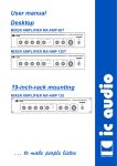
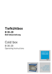
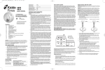
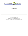
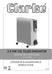
Laboratory Coolers and
Freezers
Serial Products and Custom-Made
Operating Instructions
Cold Box
Box B35B35-50
V070503
FRYKA Kältetechnik GmbH
Ohmstr. 4
Tel.
0049-711-310599-0
73730 Esslingen
Fax
0049-711-310599-29
Internet: www.fryka.de
E-Mail: [email protected]
Operating Instructions
Cold Box B 35-50
Erection
Erect the appliance the way that the very best aeration is assured viz. At least 30 cm shall remain free at
the right and the left side. Avoid locations exposed to excessive heat (max. +28°C) or direct sun rays,
because this would lead to failures of the appliance.
The cold box is only for using in dry rooms and needs a flat ground.
Before starting the cooling machine, the cold box should be still at his place min. about 12 hours.
Technical design
The housing consists of stainless steel 4301. The isolated doors is out of hard-foam and has 35 liters
capacity. The isolation of the chamber is a combination of isolation-foam and vacuum-isolation-panels.
So it is not allowed to drill holes in the isolation, cause this leads to a defect vacuum-isolation.
The cold box has the following outside dimensions: wide 585 mm, depth 765 mm, high 540 mm.
The chamber ist out of stainless steel 4301 and has a volume of 35 liters. The dimensions inside are:
W = 425 mm, D = 300 mm, H = 285 mm.
The refrigerating system at the rear side consists of a refrigerating unit with fully hermetic compressors.
There are one axial fan to cool the refrigerating unit. For regulation, there is an electronic on-off regulator
with digital display of the actual value and set-point adjuster. For further details please refer to the
technical plans.
Starting
Insert mains plug in a 230 volts/50 Hz socket with protection ground. Please take care on the allowed
power supply with 220 – 240 V / 50 Hz, cause if the differences are too high this leads to problems with
the machine.
Please check the chamber inside, this must be empty until the temperature cools down to the SET-temp.
Switch on the cooling at the standby-switch (left side of the panel) and adjust the working temperature
wanted by means of the set-point adjuster-buttons (UP and DOWN under the small blue SET display).
All buttons must be pressed for 2 seconds. This should prevent an unintentionally wrong command.
Operating range -10°C to -50°C.
The refrigerating machine starts cooling and the temperature prevailing inside is displayed in the great
blue display. Let the machine runs about 4 hours and when the temperature reach the SET-point, you can
put in the goods in the chamber.
The alarm at the right side of the panel is switched ON automatically with the standby of the cooling
machine. It is activated automatically after 3 hours or when the temp. reaches a difference of +5 K higher
the SET-temp.
Temperature Controlling
The controlling of the cooling machine is made from the electronical Board ST100. The panel of the
ST100 has 3 different displays (see script at next sides).
The controller works with 3 temp.-sensors. One PT100 sensor for measuring the inside-temp., the second
sensor for measuring the temp for the alarm-unit and the third sensor for controlling the heat of the
compressor.
The control precision is +/- 1 K.
Function of cooling machine
The machine consists of a one-stage cascade-system. The compressor cools the cools directly the
chamber.
The compressor starts some seconds behind swicth ON the standby-switch.
The compressor were switched ON / OFF by the controller for regulate the temperature.
Safety equipment
The refrigerating units are equipped with internal thermal protection to switch off the machines in the case
of excessive heat. The units may be switched on again after cooling of the compressors (approx. 1 hour).
The reason for the overheating should be checked (most times to high ambient temp. or dusty condenser).
Service connections
On the left side there is are service connections. The upper socket is a RS485 for changing the SET-point.
The 3 sockets (black-red-black) are a potential-free alarm contact for connection of an external alarmer.
The lower socket is a 10mV/K output for connection of a suitable temperature recorder. The signal means
0V = +0°C and -1V = -100°C.
Alarm Unit
The alarm unit at the right side of control panel has some different alarmfunctions.
Please see therefore the table „Status- and Error Messages“ on the next page.
The alarm unit is completly galvanized separated from the controller and this leads to a very high standard
of safety. The alarm is always in function, also when the controller has broken.
The alarm is switched ON automatically with the standby of the cooling machine. It is activated
automatically after 3 hours or when the temp. reaches a difference of +5 K higher the SET-temp.
Is the alarm in normal function and there is no actual alarm, the is a small red point in the display.
The alarm can only be switched off when the standby-switch of the cooling is off. This should prevent a
unintentionally wrong command.
The following buttons are on the alarm:
„tone off“ = With this you can switch off the acoustic signal for 15 min. If the error is always actual, the
signal comes back after the 15 min.
„reset“ = With this button you can reset a alarm signal, when there is no actual alarm.
„alarm off“ = This is the off-switch for the alarm unit. To switch of the alarm is only possible when the
cooling machine is switched off.
The alarm unit has the following red LED’s:
„.....“ (display) = At normal function is there a small red point. During a temperature error it displays the
highest value of the chamber temperature. So th euser is informed about the highest temperature during
the error and can decide if the goods are defect or not.
At other errors the display shows the error code (see in the table the discription of the codes).
„temperature alarm“ = Is on when there is a temperature alarm (see table).
„error“ = Is on at different errors (see table).
„power failure“ = Is on when the battery is defect or when the power failed.
When the alarm is on and is being in normal function (small red point) the alarm unit can make a self-test.
With this you can test if the alarm is OK. After pushing the „tone off“ button the alarm starts with the
self-test (needs 10 sec.) Is after the self-test F8 in the display, there is something wrong with the alarm
unit. Is all right, it comes back automatically to the normal display (small red point).
The following teperature alarms can be registrated:
„temperaturealarm cooling“ = This error comes from the temp. controller (blue display) to the alarm when
the actual temp. (big blue display) is more than +5 or -10 K different from the SET-temp. (small blue
display). This alarm is not possible during the cooling down time after switch on by standby.
„temperaturealarm alarm-unit“ = This error comes from the alarm-unit when the temperature is out of the
range -5°C to -60°C. This alarm is activated after a time difference (at cooling down) or when the value of
the display is reaching the range.
In the alarm is a battery installed which guaranteed the power supply for the alarm unit about 72 hours
when the power supply for the Cold Box is missing.
Attendance
All parts of the refrigerating machine are suitable for continuous operation. There is not required any
attendance. The cooling-air condenser only should be checked at regular intervals depending on the
pollution of location (usually once a year).
Please check this item first if the system fails operating. A dirty air condensor might cause the system to
overheat and fail.
For cleaning the air-condenser you can put away the right back bars and blow through the black condenser
with pressed air.
A dusty air-condenser can lead to a overheating of the cooling machine !
Trouble/repair work
Experts having discussed matters with the manufacturer or the manufacturer`s authorized staff only may
repair the refrigerating circuit of the system or intervene therein. Any reliability or warranty will cease in
the case of an infringement.
Accessories / special equipment
For the chamber of the cold box are different storage systems and a temperature recorder avaiable.
Further details are available from your dealer or from the manufacturer.
Status- and Error Messages
Display 1
Set °C
SET-temp
Display 2
Temp. °C
Actual temp.
OFF
Display 3
Alarm
Red point
Acoustic
LED 1
temp. alarm
LED 2
error
LED 3
power failure
Normal function
Cooling is switched off
Alarm is switched off
SET temp adjusting is locked
Temperaturealarm cooling
Temperaturealarm alarm-unit
Error sensor F1
Controller works like adjusted
at Parameter C10
Error sensor F2
Error sensor F3
Alarm unit is defect
Range alarm sensor F4
OFF
--Value flashs
Max Temp
Max Temp
1:3 Sek
1:3 Sek
1:3 Sek
F1
F2
F4
Out
1x pro
Min
1:3 Sek
1:3 Sek
1:3 Sek
1:3 Sek
1:3 Sek
F4
F5
F6
Max Temp
Out
F7
Is ON
Is ON
Is ON
1:3 Sek
1:3 Sek
F3
Is ON
Is ON
Is ON
Is ON
Is ON
Error sensor F4
Error sensor F5
Battery defect
Power failed, battery is on
Door is open
Seft-Test is not OK
Defect Controller
Defect Alarm Unit
Is ON
flashing
Is ON
F8
EP
1:3 Sek
1:3 Sek
EP
Description
leuchtet
leuchtet
Control Panel ST100 at Cold Box B 35-50
blue Actual-Temperature
blue SET-Temperature
SET
°C
-50
Tempature
°C
red max. Alarmtemp.
Alarm
temperature alarm
error
power failure
-50
alarm
off
On / Off Switch Alarm
Tone off for 15 min.
or Self-Test Alarm Unit
SET adjusting
(Push buttons 2 sec.)
Standby-Switch Cooling
reset
Reset - after an Alarm
on/off
All buttons must be pushed
for 2 seconds !
Parts List (Electric)
Terminal:
PE L
N1
L1
L2 1 2
3
4 5 6 PE PE
Pt100
Pt100
Frame heating
+
-
Compressor
Power Supply
Voltage: 230 V / 50 Hz
Qu.
No..
Current: 5,0 A
Description
Main Board
ST100
Control Panel
ST100
Compressor
SC 12 CLX
Condenser Fan Stage 1
GT 5 200 sg.
F1
Temperature Sensor Controller
PT 100-J
F3
Temperature Sensor Alarm Unit
PT 100-J
F4
Temperature Sensor Overheating
PT 100-1m
K5
Frame Heating
FST 10
K1
Version:
070503
B 35-50
Temperature Range -10 / -50°C
Refrigeration Diagram
Chamber
35 Liter
Y1
M1
Ft1
W1
V1
Refrigerant:
Stage 1: R 507-x
160 gr.
Oil:
Parts List
Qu.
M1
Compressor Stage 1
CS 12 CLX
W1
Condener Stage 1
FCE 14.1.210
V1
Fan Motor
GT 5 200 sg.
Ft 1
Filter Dryer Stage 1
15-6-2
Y1
Capillary Stage 1
2x1x3000
No.
Discription
Version:
070503
Stage 1
Refrigeration Diagram & Parts List
B 35-50
Temperature Range -10 / -50°C