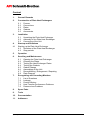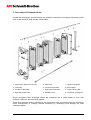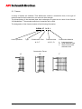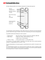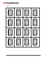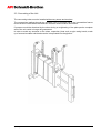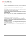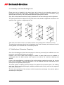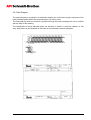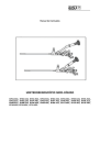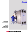
1
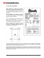
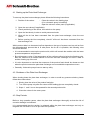
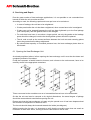
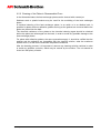
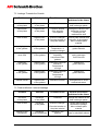
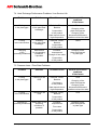
Operating
Instructions
for
SIGMA
Plate Heat
Exchangers
Content
1.
General Remarks
2.
Construction of Plate Heat Exchangers
2.1
2.2
2.3
2.4
2.5
3.
Frames
Connections
Plates
Gaskets
Accessories
Installation
3.1
3.2
3.3
Unpacking the Plate Heat Exchanger
Assembly of the Plate Heat Exchanger
Connecting of the Unit
4.
Start-up and Shutdown
4.1
Starting up the Plate Heat Exchanger
4.2
Shutdown of the Plate Heat Exchanger
4.3
Stop periods
5.
Operation
6.
Servicing and Maintenance
6.1
6.2
6.3
6.4
6.5
6.6
6.7
6.8
7.
Opening the Plate Heat Exchanger
Cleaning the Plates
Testing the Heat Exchanger Plates
Testing the Gaskets
Gasket Change
Assemblage of the Unit
Reconditioning / Enlargement / Repairing
Plate Diagram
Recognizing and Correcting Mistakes
7.1
7.2
7.3
7.4
7.5
List of Questions
Leakage
Product Mixture
Heat Transfer Performance Problems
Pressure-loss Problems
8.
Spare Parts
9.
Tools
10.
Documentation
11.
Addresses
Operating Instructions for PHE Rev. 2.0e
-2-
1. General Remarks
API Schmidt-Bretten GmbH & Co. KG is in the business of solving thermal problems since
1879, and is producing the SIGMA series of plate heat exchangers since well over six decades.
We produce a wide assortment of heat exchangers with gaskets for a broad range of heat
exchange applications.
Although our SIGMA heat exchangers are still being utilized in their traditional area of
application, that is the milk and beverage industry, our wide selection of units are employed in
nearly all industrial areas.
The wide scope of possible applications ranges from lubricating oil coolers on ships, to
refrigerant evaporators, to hot water preparators, all the way to fruit products pasteurizing units.
The wide variety of unit sizes, as well as of available plate structures, are the basis for API
Schmidt-Bretten’s optimum designed plate heat exchangers no matter for which application they
are intended.
In the following text, you will find information concerning the assembly, the functioning, and the
operating of a SIGMA plate heat exchanger.
If you still have questions concerning our products after having read the information, one of our
specialist will be happy to help you.
We wish you much success with the SIGMA plate heat exchangers.
Your API Schmidt-Bretten - Team
Operating Manual PWÜ Rev. 2.0e
-3-
2. Assembly of Dismantled Units
A plate heat exchanger, as seen below, is a pressure vessel that is composed of pressure parts
such as the lateral tie rods and the frame plates.
1 Fixed Frame Head w/ Flow Ports
5 Plate Pack
9 Upper carrying Bar
2 First Plate
6 Left-hand Flow Plate
10 End Support
3 Left Hand Flow Plate
7 Right-hand Flow Plate
11 Lower Carrying Bar
4 Right Hand Flow Plate
8 Movable Cover
12 Tie Rod w/ Locking Nut
Single corrugated heat exchanger plates are combined into a plate packet to form flow
channels, which are enclosed with gaskets.
These flow channels make it possible for the liquids that enter and exit through the connecting
holes consequently to undergo thermal treatment by conducting heat through the heat
exchanger plates.
Operating Manual PWÜ Rev. 2.0e
-4-
2.1 Frames
A variety of frames are available. Their differences consist in construction form, in the type of
material used for their construction, as well as in their strength.
The dimensioning of the standard plate heat exchangers is based on the rules of the German
“AD-Merkblätter”. The standard selection of materials refer to DIN.
The designation of the frames consists of the following information:
SIGMA 27 N B L
Line of products
Type
Construction Form
Pressure class
N, S, T
A, B, C, D
Construction Material
L
N
V
Lacquered steel
Solid stainless steel
Steel covered with
stainless steel
Construction Forms
“N”
Operating Manual PWÜ Rev. 2.0e
“S”
“T”
-5-
2.2 Connections
SIGMA plate heat exchangers come equipped with a range of different connection types
according DIN-Standard.
The choice of corrosion-proof material used for the connections depends on the medium that is
to undergo the thermal process. A higher alloyed and more resistant material is required for the
connections and the lining, if a more aggressive medium is to be treated.
A cost-effective variation would be to employ the same material utilized in the plate gaskets for
the lining of the connections.
Additional connections used for ventilation or draining usually have a smaller nominal width than
the product connections.
The diagram below shows the letters attributed to the position of the connections.
Fixed Frame Plate
Moving Cover
2.3 Plates
One of the main components of the heat exchanger is the plate package. The number of plates
and the type of plate corrugation used in the heat exchanger unit depends on the type of
thermal process that is to take place.
The flow path through the plate package also depends on the thermodynamic requirements of
the plate heat exchanger.
Operating Manual PWÜ Rev. 2.0e
-6-
All heat exchanger plates are in principle composed of a single plate segments.
Inlet Port
Leakage Section
Distribution Segment
(Triangle)
Main heat exchange
area
(Rectangle)
Collecting Segment
Passing Port
Outlet Port
The composition and the temperature of the media, which are to take part in the thermodynamic
process, determine the type of materiel used for the manufacturing of the heat exchange plates.
As possible materials the following are used in general:
• Stainless Steel:
AISI 304, AISI 316, AISI 316L, AISI 316TI, AISI 904L, SMO 254
• Nickel Alloys:
2.4066 (pure nickel), 2.4819 (Hastelloy C-276),
2.4858 (Incoloy), 2.4360 (Monel)
• Titanium / -alloys:
3.7025 (titanium Grade 1), 3.7225 (titanium-Pd)
The thickness of the plate material is depending on the plate type and the required pressure
resistance. It ranges between 0.4 mm and 1.15 mm.
The flow-characteristics of the plate gaps are interlocked with the profile of the plate corrugation.
API Schmidt-Bretten disposes over a wide assortment of plates with varying corrugations. Each
has its own specific hydraulic and thermodynamic properties, as well as in product distribution
and cleaning behavior in relation to the product consistencies.
Operating Manual PWÜ Rev. 2.0e
-7-
Plate packages can consist of plates with varying plate corrugation patterns. The following
corrugation patterns are available for the optimizing of thermodynamic flow paths.
Each plate heat exchanger is optimized according to the specific use in mind. Consequently,
H-Corrugation
W- Corrugation
Y- Corrugation
Z- Corrugation
V- Corrugation
F- Corrugation
various heat exchanger units have different arrangements and flow paths through which the
product is fed.
A parallel or serial arrangement can be achieved by opening or closing the outlet ports.
The plates, which do not have four open inlet / outlet ports, are called “turning plates”. For a
clear identification of the turning plates, a nomenclature consisting of letters, which are attributed to the various inlet and outlet ports, is used (refer chapter 2.2).
When looking at a heat exchanger plate, with the plate side which holds the gasket facing
towards you, if the inlet and outlet port are situated on the left side then this is a left plate. When
the outlet ports are positioned on the right side this indicates that it is a right plate.
Operating Manual PWÜ Rev. 2.0e
-8-
Turning Plates
AR
BR
CR
DR
BL
AL
CL
DL
ER
FR
GR
HR
FL
EL
HL
GL
IR
JR
KR
LR
JL
IL
LL
KL
MR
NR
OR
PR
NL
PL
OL
ML
Operating Manual PWÜ Rev. 2.0e
-9-
Start Plates
AAR/EAR
ABR/EBR
ACR/ECR
ADR/EDR
ABL/EBL
AAL/EAL
ACL/ECL
ADL/EDL
AER/EER
AFR/EFR
AGR/EGR
AHR/EHR
AFL/EFL
AEL/EEL
AHL/EHL
AGL/EGL
AIR/EIR
AJR/EJR
AKR/EKR
ALR/ELR
AJL/EJL
AIL/EIL
ALL/ELL
AKL/EKL
AMR/EMR
ANR/ENR
AOR/EOR
APR/EPR
ANL/ENL
APL/EPL
AOL/EOL
AML/EML
Operating Manual PWÜ Rev. 2.0e
-10-
2.4 Gaskets
Every heat exchanger plate of a gasketed plate heat exchanger is fitted with a complete gasket.
The gaskets keep the fluids that flow through the heat exchanger separated from each other
and contained within the unit.
Each heat exchanger plate is fitted with two ring- and two field gaskets. The only exceptions are
the plates, which face the frame heads.
Diagonal Gasket
Field Gaskets
Leakage Groove
Ring Gasket
Fastening Clip
Within the gasket is a leakage area with a leakage groove. As soon as diagonal- or ring gasket
is defective this leakage groove makes the leak visible on the outside.
The functioning of these leakage grooves is guaranteed as long as the gasket has not lost its
original shape due to thermal influences, or that the leakage grooves have become congested
due to the impurities contained in the product, or that the plate packet was not tightened
properly below the given final clamping dimension.
In general, there are two ways of fixing the gaskets to the heat exchanger plates:
• The fixing of a gasket to a plate by means of adhesives:
A special adhesive is placed as a complete layer into the heat exchanger plates’ gasket
groove. After the gasket has been fitted in and the adhesive has hardened, the gaskets and
plates are joined permanently.
This method of fixing the gasket to the plate is especially advantageous for systems, which
have to be opened for cleaning on a regular basis.
The gaskets loose their effectiveness with time and then have to be exchanged. When
gaskets are changed, they have to be removed carefully and new ones have to be fixed to
the plates.
Depending on the gasket material and quality, this procedure may be performed directly on
site.
It is however highly recommended that the plates be returned to the manufacturer, who will
then perform the gasket change.
Operating Manual PWÜ Rev. 2.0e
-11-
• Adhesive free gasket fixing system
When using an adhesive free gasket fixing system, in contrast to the adhesive fixing system,
the gasket is held in place through a number of fixing points. The fixing points are determined
by the size of the heat exchanger plate.
The fixing of the gasket to the plate is achieved through lateral mounting clips, which are
clamped into the recess on the plate edge.
The changing of the gasket is easy and can be performed on site.
When choosing the material for the gaskets, the same criteria as for the choice of heat
exchanger plate material has to be kept in mind. The choice of material depends on the type of
medium to be treated as well as the temperature upon entering and exiting the heat exchanger
unit.
The following are the standard elastomer gasket materials that are available:
NBR
EPDM
FPM
CSM
Chloroprene
Silicone
Apart from these, for certain plate types it is possible to employ compressed-fiber materials.
The service life of a plate heat exchanger gasket depends on a variety of factors.
The following factors have an influence on the service life of the gasket:
• the operation of the heat exchanger
(continuous or discontinuous operation)
• the maximum operation pressure
• the maximum or minimum operation temperature
• temperature- or pressure load changes
• the composition of the products which undergo the thermal treatment, their additives
as well as the mediums used during the cleaning processes
• mechanical stress due to irregular or to tightly adjusted frames
Operating Manual PWÜ Rev. 2.0e
-12-
2.5 Accessories
2.5.1 Intermediate Frames and Intermediate Plates
For a range of applications several sections with varying thermodynamic functions can be
installed within a plate heat exchanger, as is the case within a food stuff pasteurizer with a
cooling, a heating, and a heat recovery section.
Nevertheless, each section requires its own inlet and outlet ports. Intermediate frames which
are built-in to serve as separation between two adjacent sections can be equipped with the
appropriate connections for the functioning of that section.
In contrast, intermediate plates without connections merely serve as separation between two
adjacent sections.
2.5.2 Protection Cover and Insulation
Heat exchangers with operating temperatures of over 50 °C or under –10°C should be fitted
with a protection cover in order to avoid any injuries through contact.
Direct contact with the heat source can be avoided through the mounting of protection covers.
These protection covers, which are made out of thin stainless steel, are fitted over the plate
pack.
Another safety feature of the protection cover is that it also serves as splash guard against the
mediums contained within the heat exchanger in case of a gasket leak due to aging of the
gasket.
Compared to the large internal heat exchange surface, the exterior of the heat exchangers is
relatively small. Although the exterior surface is not very extensive, for some applications it
would be advantageous to install an isolation barrier.
The plate heat exchange may be insulated using one of two methods. The unit can either be
completely insulated using a solid insulation which encases the whole unit and which can be
removed in one piece, or only the plate pack may be insulated so that any heat losses towards
the outside are avoided. In this case, the plate pack is covered with a protection cover, which
includes a layer of insulation on the inside.
It is the responsibility of the operator to ensure that the proper safety precautions are taken so
that no injuries to persons, or damage to the environment occur in case of heat exchanger
malfunction or damage leading to leakage.
2.5.3 Safety Precautions Against Outer Influences
In general, it is not possible to protect a heat exchanger from outside influences such as heat or
other atmospheric influences.
It is however necessary to foresee certain safety measures. In case of a fire the heat exchanger
unit must be depressurized through a built in automatic control system in order to avoid an
increased risk of damage caused by the pressurized mediums contained within the unit.
As a preventive measure against possible damage from aggressive substances contained in the
surrounding area, all parts of the heat exchange unit, such as the pressure frames, the heat
exchange plates, and the gaskets must be pre-treated accordingly.
When choosing the location of the heat exchanger unit it should be kept in mind that, UV or
other rays can have a negative effect on the gaskets and thus shortening the service life of the
seal.
Operating Manual PWÜ Rev. 2.0e
-13-
3. Installation
3.1 Unpacking of the Heat Exchanger Unit
Units, for which the net weight is to found in the technical documentation, usually are delivered
lying flat on a pallet.
When transporting these pallets with a fork lift it is important to verify that the supporting surface
of the forks is long enough to support the pallet in order to avoid possible braking of the pallet
and damage the heat exchanger unit.
The unloading of the unit may only be done with the proper machinery such as flat lifting slings,
which can be fastened to the securely bolted frame and/or to the loops, which are foreseen
especially for the transport of the unit. Under no circumstances are the connection tubes or
intermediate frames to be used in the unloading and transporting of the unit.
All lifting loops must be used during the transport in order to avoid a warping of the unit caused
by improper transport.
3.2 Mounting of the Plate Heat Exchanger
First of all the unit has to be aligned in the proper assembly order.
Then the floor supports for the frame and the end support must be set up.
For units that have an additional supporting leg on the lower-carrying bar, the supporting leg
must be adjusted so that it has a proper contact with the floor.
Enough space should be foreseen around the heat exchanger unit. Depending on the model
about 1,5 m of space is needed, so that during the servicing of the unit by our erecting
engineers, plates can be removed from the plate pack and spanners can be used without any
spatial restrictions.
Tubular connections situated on the movable pressure plates as well as on the intermediateframes must be easily accessible for servicing.
Under certain circumstances, it may not be possible to deliver the heat exchanger as an
assembled unit. Even if the unit is delivered in a disassembled state, before it left the production
plant it was tested for quality of build and underwent all the required pressure tests. However,
after the unit is assembled within your facilities before it is put into operation it must undergo
another pressure test. All the required information is to be found in the technical documentation.
Operating Manual PWÜ Rev. 2.0e
-14-
3.3 Connecting of the Unit
The connecting tubes must be installed without any stress and tensions.
The connections leading through the movable cover or through one of the intermediate frames
must remain movable within the theoretic maximum and minimum dimensions.
If pressure would be absorbed by the tubes during a re-tightening of the plate pack a complete
seal of the unit could no longer be guaranteed.
In order to avoid any stresses on the tubes, expansion joints such as pipe swing bends, made
up of several movable tube bends can be incorporated into the pipeline.
Operating Manual PWÜ Rev. 2.0e
-15-
4. Start Up and Shutdown
Before starting up a plate heat exchanger,
make sure that the admissible pressures and
temperatures indicated on the name plate are
not exceeded. Safety measures in case of
exceeding temperature and pressure are to be
observed.
The compatibility of the media to be treated
with the materials used for the construction of
the plate heat exchanger is to be checked
before the start up of the unit.
It may be possible that the tie rods become
loose during transportation of the unit in a
depressurized state, or after the first few days
of operation, simple retighten the tie rods.
Before restarting the unit it should be checked
that the measurements regarding size and
uniformity of all tightening bolts correspond to
the dimension A (see drawing).
To avoid pressure shocks during start-up and shutdown of a heat exchanger unit appropriate
components should be built into the unit or the technical operation conditions should be adjusted so that a minimum of pressure shocks occurs.
After prolonged operating periods with on and off phases it is possible, especially when using
compressed fiber gaskets, that leakage occurs when the heat exchange unit is cold. These
leaks get smaller with ever increasing temperatures. They are a part of the natural setting
phenomenon of the gaskets.
Operating Manual PWÜ Rev. 2.0e
-16-
4.1 Starting up the Plate Heat Exchanger
To start-up, the plate heat exchanger please follow the following instructions:
1. Position of the valves:
- Close the valves in the feeding pipe
(if no volumetric pump is installed).
- Open the valves in return pass (if applicable).
2. Open the vent valves (if applicable).
3. Check positioning of the valves, then switch on the pump.
4. Open the inlet slowly in order to avoid pressure shocks.
5. When all the air has been evacuated from the plate heat exchanger, close the vent
valves.
6. Before opening the inlet completely, check if all the air has been evacuated from the
heat exchange unit.
Which product side is to be started-up first depends on the type of system used, as well as from
the thermodynamic process that is to take place. As far as it is possible, the following rules
should be followed:
• It is recommended to start-up the product side, which will contain the medium with the lower
process temperature and pressure.
• By cold pressure cycles, if the temperature of the cooling medium is below the freezing point,
then the medium to be treated should be fed into the heat exchange unit first in order to
avoid a freezing up of the unit.
• It is also important to note that the sequence of the product feed should be chosen so that
when the product enters the plate heat exchanger no uncontrollable evaporation occurs.
• Generally: Volumetric pumps have to start up softly.
4.2 Shutdown of the Plate Heat Exchanger
When shutting down the plate heat exchanger, in order to avoid any pressure shocks, please
follow these instructions:
1. Slowly close the valve of the product feed pipe.
2. Turn off the pump only after the valves of the feeding pipe are completely closed.
3. Steps 1. and 2. are to be repeated for the second product side.
4. Close the valves for the return pass.
4.3 Stop Periods
Before a long operation pause, clean the plate heat exchanger thoroughly so that the risk of
corrosion damage is minimized.
It is recommended that the tension is released within the plate heat exchanger and only to
retighten the unit before it is to be put back into operation.
Operating Manual PWÜ Rev. 2.0e
-17-
5. Operation
Each plate heat exchanger is designed and built for specific thermodynamic operations with
processing, cleaning, and sterilization cycles taken into account.
Before the heat exchanger unit can be used for the processing of any media other than
originally planed, all parts of the unit which come into contact with the medium, such as gaskets,
heat exchange plates and connections, have to be tested for compatibility with the new medium.
The plate heat exchanger may only be put into operation after it has been verified that the unit is
capable of processing the new medium.
It is the responsibility of the units owner to ascertain that upon feeding a new product into the
unit no chemical or thermal reactions will occur due to reaction with previously treated fluids
which remained in the unit.
If the possibility of such a reaction exists then the heat exchange unit must be completely
drained before a new fluid is pumped in.
If during a thermal process the operating temperature, operating pressure or the flow rate of the
product feed has to be changed, the adjustment should be done slowly and over longer span of
time.
In general, a continuing operation cycle is best suited for a heat exchange unit.
If however the continuing operation of the heat exchange unit is not possible due the required
thermal treatment conditions, precautions have to be foreseen in order to avoid rough switch
over to a different thermal process function.
Often occurring pressure variations even in small amplitudes may have a negative effect on the
service life of the gaskets.
If possible it should be avoided that a plate heat exchanger constantly undergoes extreme temperature variations, from being hot to completely cold, since this process speeds up the aging of
the gaskets.
To minimize the stress and to extend the service life on the gaskets additional spring joint
packages can be built into the tie rods.
Not only, the variations in operation conditions can damage the heat exchanger unit, but
processes, which take place within other parts of the system. On- or off-switching of other
components may cause pressure shocks that are carried all the way through the system to the
heat exchanger unit.
In this case, the demands for the heat exchanger units’ rigidity should be compared with the
actual parameters given for the original function of the unit.
With a plate heat exchanger the risk exists that a plate cracks occurs. This problem may be
caused through the deposit of corrosive materials on the heat exchanger plates or due to
pressure variations that occur over longer operation periods.
In case of a plate crack the mixing of the products may occur.
If one of the products must be kept clean, and may not be contaminated by the other medium
taking part in the thermodynamic process, possible contamination in case of a plate crack can
be avoided by pumping this medium through the unit at a much higher pressure than the other
fluid.
Operating Manual PWÜ Rev. 2.0e
-18-
6. Servicing and Repair
Due the great number of heat exchange applications, it is not possible to set a standard time
interval at which the unit must be serviced.
According to need, the following repairs and tune-ups have to be carried out:
• In case of leakage, the unit has to be retightened.
• If leaks persist after the unit has been retightened, other causes have to be investigated.
• If leaks can not be stopped because the unit has been tightened up to the final platage
(see name plate), then the gaskets have to be changed.
• For units that have been in use since a longer period, not only the gasket at the leakage
spots should be changed, but also the whole gasket system should be replaced.
• The tie rods as well as the contact surfaces between the lock nuts and centering plates
has to be greased before being retightened.
• By reduced heat capacity or increased pressure loss, the heat exchanger plates have to
be cleaned.
6.1 Opening the Heat Exchanger Unit
As already explained above, before opening the heat exchange unit it must be shut down and
completely drained of its content.
Fluids that represent a health hazard to humans, and a threat to the environment, have to be
carefully stored in the appropriate containers.
Tubes connected to the movable cover or to intermediate frames have to be dismantled.
So that the unit can later be returned to its original dimensions, the actual degree of platage
should be measured and noted before opening the unit.
Please note that the heat exchanger unit may only be opened once it has been depressurized
and cooled to a temperature of less than 40°C.
The tie rods should always be loosened towards the inside (see diagram).
While loosening the tie rods, it is important to verify that the movable cover does not reach an
inclination of more than 10mm, as long as there is still strain on the tie rods.
Operating Manual PWÜ Rev. 2.0e
-19-
6.2 Cleaning of the Plates
Different options exist for the cleaning of the heat exchanger plates:
6.2.1 Cleaning in Place (CIP)
When cleaning the unit with the heat exchanger plates in place (CIP) a cleaning solution
takes the place of the product. For the best cleaning results, the cleaning solution should be
pumped through the unit in the opposite direction as the usual product flow.
A higher flow rate of the cleaning solution ensures an even better cleaning result.
In case that the pressure pumps are not strong enough to further augment the flow rate
during the cleaning cycle another option remains. Through the addition of compressed air,
the turbulence of the cleaning solution within the unit is increased and better cleaning results
are obtained.
The compatibility of the cleaning substance with the plates, connections and gasket materials
as well as gasket adhesives must be tested before the cleaning of the unit occurs.
The exact cleaning procedure, regarding cleaning substance, volume of cleaning solution, as
well as duration of the process, depends on the type of construction materials used in the
heat exchanger unit as well as the type of deposits to be removed. We recommend that you
take up contact with a cleaning agent manufacturer.
We recommend the following DIN 11 483 certified cleaning and disinfecting agents:
Cleaning and disinfecting agent
Concentration
[wg.-%]
Contact time Temperature
[h]
[°C]
Gasket
Material
Alkaline cleaning agent with NaOHbase
up to 5
no limit
up to 90
NBR
EPDM
Combination cleaning agent
NaOH + Na-Hypochlorite
up to 5
1
up to 70
NBR
EPDM
Acidic cleaning agent with Phosphoric
acid base
up to 5
1
up to 90
NBR
EPDM
Acidic cleaning agent with nitric acid
Base
up to 2
0,5
up to 50
NBR
EPDM
Acidic cleaning agent with citric acid
base
up to 4
1
up to 40
NBR
EPDM
Disinfecting agent with peracetic acid
and / or hydrogen peroxide base
up to 1
up to 2
20
NBR
EPDM
-
no limit
120
NBR
EPDM
Hot water
Operating Manual PWÜ Rev. 2.0e
-20-
6.2.2 Cleaning of the Plates in Disassembled Form
In the dismantled state, the heat exchanger plates can be cleaned with a steam jet.
Stainless steel or plastic brushes may be used for the scrubbing of the heat exchanger
plates.
A chemical cleaning of the heat exchanger plates, in an acidic or in an alkaline bath, is
possible for plates with non-adhesive gaskets as long as the gaskets are removed before the
plates are placed into the bath.
The chemical resistance of the plates to the chemical cleaning agent should be checked
before the plates are submerged into the bath, in order to avoid any possible damage to the
heat exchanger plates.
For plates with adhesive-gaskets, the same precautions apply. It should be verified that the
gaskets and the adhesive are compatible with the cleaning solution, what the maximum
contact time is, as well as the maximum temperature tolerance.
After the cleaning process, it is important to remove any cleaning solution residues in order
to avoid any possible corrosion, which may be caused by the solution. The unit should be
rinsed out with plenty of water.
Operating Manual PWÜ Rev. 2.0e
-21-
6.3 Inspecting the Heat Exchanger Plates
The ware of the heat exchanger plates can be checked visually, damages of the plates such as
scratches, deformities or corrosion can be seen with the naked eye.
In order to detect any plate cracks one of the following procedures is to be followed:
One of the circuit paths is to be filled with a medium while the other circuit path is to remain
depressurized.
If the medium filled circuit path shows a significant drop in pressure, and there are no leaks to
be seen from the outside, then it is certain that there is a plate crack within the unit. It is recommended that this test be performed in all the units circuit paths.
To detect plate cracks in a depressurized state a dye penetration method is used. One side of
the plates is sprayed with a red color, while the other side is impregnated with a white color
sensitive developing agent.
If there are any cracks or holes present, which have penetrated through the heat exchanger
plates the red color, through diffusion, will appear as a spot on the white side of the plate.
6.4 Inspecting the Gaskets
Through a visual inspection, deformities of the gasket, improper fit into the gasket groove or
damage of the gasket or of the adhesive, are easily detected.
To test the functioning of the gaskets, a single sided circuit pressure test can be performed.
It is certain that the gaskets are functional, under the condition that the leakage grooves are not
deformed or blocked with dirt, when no leakage is detected on the outside of the unit when
using the single circuit pressure test.
A very minute, drop like leak can be fixed by simply re-tightening the unit, as long as the unit
has not been tightened to its final platage, and the gaskets have not suffered any thermal,
mechanical or age related damage.
If the leak is not corrected after re-tightening of the unit, the problem might have had some other
reasons. The gaskets have to be inspected because they may have shifting out of place or be
damaged.
Operating Manual PWÜ Rev. 2.0e
-22-
6.5 Changing the Gaskets
Adhesive-free gaskets can be changed by simply opening the heat exchanger unit and without
having to remove the plates.
It is important to check that there is no dirt on or under the gasket, as well as in the plates’
gasket groove.
For heat exchanger plates with adhesive fixed gaskets the following procedure applies: (EPDM
gaskets are an exception, it is recommended that plates with EPDM gaskets are sent back to
the manufacturer who will perform the gasket change).
• Dismantling of the plates.
• Removal of the gasket either through the light application of a flame to the back of the
gasket groove (annealing colors through the applied heat should be avoided) or through
the submergence of the plate in a nitrogen liquid bath.
• The gasket groove must be cleaned, and all adhesive as well as gasket residues must be
removed.
• Roughen the gasket groove through sand blasting or sandpaper.
• Apply the adhesive into the gasket groove with a paintbrush.
(only original API Schmidt-Bretten – adhesive is to be used)
• Clean the gaskets with a lint free cloth, which was drenched in acetone.
• Place the gaskets into the gasket grooves.
• Place about 20 plates in between a wooden frame, which is then compressed with a
parallel screw clamp.
• Let the adhesive dry for approximately 12 hours at room temperature.
• Remove any excess adhesive on the gasket surface.
• Reinstall the plates according to the plate diagram.
More detailed instructions are available from our head office upon request.
Operating Manual PWÜ Rev. 2.0e
-23-
6.6 Assembly of the Heat Exchanger Unit
Plates have to be installed in the same layout as is shown in the instruction manual. It is
important to check that each plates’ corrugation pattern, connecting ports, orientation (every
second plate is turned by 180°) and position within the plate pack is correct.
Only after all the plates have been properly installed can the heat exchanger unit be tightened.
The plate pack should be clamped evenly and the tie rods should be tightened crosswise in the
opposite order as when un-tightening the unit.
Take care not to tilt the cover to one side or bend it at any stage (max. inclination 10 mm).
The plate heat exchanger should not be tightened more than necessary so that the service life
of the gaskets is not reduced due to excessive pressure.
6.7 Modifications / Extensions / Repairing
One of the advantages of plate heat exchangers is that they can easily be modified to suit new
production needs without greater proceedings.
However, ever time a plate heat exchanger is rebuilt its name plate has to be updated or
exchanged, since the plate quantity and sequence, as well as the maximum clamping was
altered.
If due to the reconditioning or enlarging of the unit the bottom carrying bar and/or the tie rods
have to be exchanged, a special permission is to be obtained from the manufacturer since
these parts are important pressure parts.
The same applies to welding work that needs to be performed on pressure parts. The welding
work may only be performed through qualified specialists after having received the approval
from the manufacturer.
The laws and regulations of the country in which the plate heat exchanger is to operate apply to
the start-up of the system.
Operating Manual PWÜ Rev. 2.0e
-24-
6.8 Plate Diagram
The plate diagram is contained in a schematic drawing out of which the proper sequence of the
heat exchange plates within the heat exchanger unit can be read.
The flow paths by which the medium is pumped through the heat exchange unit can be verified
with the help of this drawing.
The identification of each individual plate can be seen in detail in a previous chapter. In this
way, each plate can be identified on the basis of its perforations and its orientation.
Operating Manual PWÜ Rev. 2.0e
-25-
7. Recognizing and Correcting Mistakes
During the operation of the heat exchanger unit it is possible that malfunctions occur. These
malfunctions may be caused by outer influences or by the circumference of the heat exchanger
unit.
Below you will find a list of questions you should try and answer before taking up contact with
API Schmidt-Bretten so that we can help you more quickly. Included below you will also find
registers which include possible malfunctions with their possible causes and solutions to these
problems as well as suggestions how to avoid these problems.
7.1 List of Questions
• Is there a leakage problem?
• Where is the leakage (outer or inner leakage, on the plate pack, on the connections,
between the plate pack and the frame) ?
• How strong is the leak (drops or continuous stream) ?
• When does the leakage occur (permanent, during operation, during on- or off-switching,
during production or cleaning) ?
• Is the heat exchanger unit in continuous operation ?
• Do pressure variations or temperature variations occur ?
• How many plates are presently contained in the plate pack ?
• Is the unit functioning with the original number of heat exchanger plates ?
• What is the present platage ?
• How large is the theoretic final platage ?
• Is the heat exchanger unit clamped without inclination ?
• Are there any stresses between the pipelines connections to the frame, cover, or intermediate frames?
• Are the gaskets still in place (even pattern along the plate pack) ?
• How old are the plates and the gaskets ?
• What is the composition of the products and cleaning agents used in the unit ?
• Is there a problem with the heat capacity (flow rate or outlet temperature) ?
• How long has the unit been functioned without problems ?
Operating Manual PWÜ Rev. 2.0e
-26-
7.2 Leakage Towards the Outside
Problem
Solutions
Possible causes
How to avoid these
problems in the future
Corrosion
of the plates
Replacement
of the plates
Chlorides
Change the material of the
heat exchanger plates
Deformation
of the plates
Replacement
of the plates
Pressure shocks
Over-pressing
of the plates
Change the valves or the
production process.
Teaching of the
maintenance stuff
Plate cracks
Replacement
of the plates
Pressure changes,
Chemical attacks on
the plate material
Thicker plate material and
reduction of the platage.
More resistant plate
material
Aging
of the gaskets
Replacement
of the gaskets
End of lifetime,
Temperature- or
pressure-changes
Change the
gasket material
Leakage
when cold
Replacement
of the gaskets
Aging of the gaskets,
especially
compressed fiber
gaskets
Installation of
spring packages
on the tie rods
Hardening
of the gaskets
Replacement
of the gaskets
Inadequate chemical
resistance,
Temperatures
too high
Change the
gasket material
Swelling
of the gaskets
Replacement
of the gaskets
Inadequate chemical
resistance,
Temperatures
too high
Change the
gasket material
Gasket cracks
Replacement
of the gaskets
Mechanical stress
Arrangements to avoid
mechanical stress
7.3 Product Mixture / Internal Leakage
Problem
Solution
Possible cause
How to avoid these
problems in the future
Corrosion
of the plates
Exchange
of the plates
Chlorides
Change the material of the
heat exchanger plates
Plate cracks
Exchange
of the plates
Pressure changes,
Thicker plate material,
Reduction of platage.
More resistant plate
material
Compensatory expansion
joints or articulation elbows
Chemical attacks on
the plate material
Braking of the
connections
Exchange
of the connections
Operating Manual PWÜ Rev. 2.0e
Stresses in the
pipeline
-27-
7.4 Heat Exchange Performance Problems / Low Service Life
Problem
Solution
Possible cause
How to avoid these
problems
in the future
Fouling
in the plate gaps
Cleaning
of the plate heat
exchanger
Particles, Fibers,
Bacteria
Filters
Composition
of the product
Hard deposit due to
high temperature
Fouling
in the connections
Changing
of the
operating conditions
Cleaning
of the plate heat
exchanger
Particles, Fibers,
Bacteria
Switch back
to old operating
conditions,
if possible
Entrance
temperatures
Changing of the
plate arrangement
Changing of the
temperature difference
between cold and hot side
Filters
Composition
of the product
Change of flow rates
Changing of the
plate arrangement
or plate type
Composition
of the product
7.5 Pressure Loss- / Flow Rate Problems
Problem
Solution
Possible cause
How to avoid these
problems
in the future
Fouling
in the plate gaps
Cleaning of the
PHE
Particles, Fibers,
Bacteria
Filter
Consistency
of the product
Hard deposit due to
high temperature
Fouling
in the connections
Cleaning of the
PHE
Particles, Fibers,
Bacteria
Changing of the
plate arrangement
Changing of the
temperature difference
between cold and hot side
Filter
Composition
of the product
Changes of
operating conditions
Switch back to old
operating
conditions, if
possible
Entrance
temperatures
Flow rates
Changing of the
plate arrangement
or plate type
Composition
of the product
Operating Manual PWÜ Rev. 2.0e
-28-
8. Spare Parts
It is recommended to keep spare parts in stock at the production site, as far as the plate heat
exchanger is a necessary and urgent component of your production process.
Depending on the possible off-time the following variants of spare parts vary:
• Spare gaskets
• Single spare plates
• Complete gasketed plate package
• A complete stand-by PHE
Normally it is no necessary to keep spare parts for the frames or intermediate frames in stock at
the facility.
Keep the following conditions for the storage of the above mentioned spare parts:
• Gaskets and gasketed plates should not be stored for more than two years
• Don’t store the parts outside
• Storage is good at temperatures below room temperature
• If possible store the parts in a dark room and avoid neon light
• The atmosphere in the store has to be free of solvents or ozone
9. Tools
For best handling for mounting or maintenance work with the plate heat exchanger, several
tools should be available.
• Spanner for smaller units
• Wretch-spanner for larger units
• Electric or hydraulic screwing machine for very large units
• Lifting gears as fork lifter or a crane should be on site, if frame parts have to be changed
Operating Manual PWÜ Version 2.0
-29-
10. Documentation
The standard documentation contains the following papers and pieces:
• Name Plate
• Dimensioned drawing of the unit
• Parts List
• Plate Diagram
• Technical Datasheet
• Operating Manual
Optional the documentation can be supplemented by:
• Manufacturer Certificate
• Declaration of conformity (where appropriate)
• Material certificate
• Approval drawings
• Documentation of inspection by an inspection company (for example TÜV, GL)
Operating Manual PWÜ Version 2.0
-30-
11. Addresses
Feel free to contact our stuff in the main facility in Bretten or in one of the subsidiaries outside
Germany, if you have any question or need any information about spare parts or other products
of API Schmidt-Bretten.
API Schmidt-Bretten GmbH & Co. KG
S.A.R.L. Schmidt-Bretten France
Pforzheimer Strasse 46
Z.A.C. de la Coix Prunelle
D-75015 Bretten
F-27220 Saint André-de l’Eure
Germany
France
Phone
+49 / (0)7252 / 53 - 0
Phone
+33 / (0) 232 60 26 80
Fax
+49 / (0)7272 / 53 - 200
Fax.
+33 / (0) 232 60 28 77
API Schmidt-Bretten Inc.
Schmidt-Bretten Espana S.L.
2777 Walden Avenue
Avda. de la Fama 66-72
Buffalo, New York 14225
E-08940 Cornella de Llobregat
USA
Spain
Phone
+1 / 716 / 68 - 46 700
Phone
+34 / 93 377 31 92
Fax.
+1 / 716 / 68 - 11 125
Fax.
+34 / 93 377 32 93
Schmidt-Bretten Ned. B.V.
Schmidt-Bretten Romania S.R.L.
Apolloweg 7 D/E
Sos. Vergului, Nr. 59, Sect. 2
NL-8938 AT Leeuwarden
Bucaresti
The Netherlands
Romania
Phone
+35 / 58 / 288 55 80
Phone
+40 / 1 / 255 21 95
Fax.
+35 / 58 / 288 50 05
Fax.
+40 / 1 / 255 33 36
Schmidt-Bretten India Pct. Ltd.
124/3, Vitthalwadi Road
411 030 Pune
India
Operating Manual PWÜ Version 2.0
Phone
+91 / 20 / 433 86 42
Fax.
+91 / 20 / 433 79 13
-31-
Important Note !!!!
The plate heat exchanger is only allowed to operate under the specified operating
conditions otherwise the guarantee and all other liabilities of the manufacturer
will expire !
API Schmidt-Bretten GmbH & Co. KG
Pforzheimer Strasse 46, D-75015 Bretten, Germany
Phone +49 7252 53-0, Fax +49 7252 53200, Email: [email protected]
API Schmidt-Bretten GmbH & Co. KG
Pforzheimer Straße 46
D-75015 Bretten - Germany
Registergericht Bruchsal HRA.-Nr. 378-Br.
Persönlich haftende Gesellschafterin :
API Schmidt-Bretten Verwaltung GmbH
Sitz Bretten, Registergericht Bruchsal HRB.-Nr. 611-Br.
Managing Director: Norbert F.K. Jähnke
Phone (-7252) 53-0
Bank Accounts :
Sparkasse Bruchsal Bretten
Postbank Karlsruhe
Landesgirokasse Stuttgart
Fax (-7252) 53-200
BLZ 663 500 36
BLZ 660 100 75
BLZ 600 501 01
Kto. 05 030 929
Kto. 78 753
Kto. 25 125 10