1
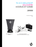
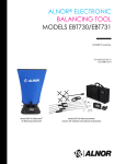
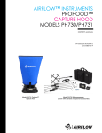
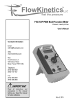
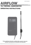
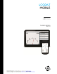
TM
9020023/G/797
SPECIALISTS IN AIR MOVEMENT TECHNOLOGY
TA-2
RANGE
Operating
1
OF THERMAL
ANEMOMETERS
instructions
Introduction
output proportional to meter
The T A-2 range of thermal
deflection, and are intended for
use with a compatible data logger
anemometers comprises three
models, scaled in both metric and
such as the Airflow AM-2.
imperial units. Each model may
As built, the output is set to 0-1
be used for velocity or temperature
volt, but may be factory set to
measurement. For full technical
between 0.5 and 2.0 volts if
details of the range see section
required. The output is not user
8 'Specification'.
adjustable.
All the instruments in the range
are fitted with telescopic probes
2.
To fit battery
cells
with a maximum diameter of
Instruments in the T A-2 range are
8mm. The TA-2 is therefore very
supplied without battery cells.
suitable for measurement in small
Four 1.5 volt M size cells are
ducts or where large access holes
required, which may be standard,
are not acceptable.
alkaline or rechargeable.
The velocity sensitive thermistor
Battery cells are accessible
in the probe is compensated
through the slide and 'snap in'
for
changes in airstream temperature
cover in the underside of the
by a second thermistor which is
instrument. Remove the batteries
also used to measure the
by means of the tape, but the use of
airstream temperature. As part of
a small screwdriver or similar tool
the manufacturing
will assist the removal. Low battery
process each
instrument is checked and calibrated
condition is indicated by a red
by wind tunnel in a temperature
light on the front of the instrument.
controlled calibration room.
Replace the battery cells as soon
All TA-2 models are fitted with
as possible if this occurs or
0-1 volt outputs. These give an
incorrect reading may result.
Instruments in the TA-2 range
are very easy to operate. Before
3.4,
'snaps in' at the rear underside
using the instrument, users
of the instrument case.
should thoroughly familiarise
3.1.
3.5.
3.3.
Velocity scale in metres per
themselves with its features.
Three position slide switch:
3.6.
Up -velocity.
centre -off.
Temperature scale in degrees
C and F.
3.7
Green light. Flashes when unit
second and feet per minute.
down -temperature.
3.2.
Battery cover. This slides and
is switched to either velocity or
Always switch off when not in use.
Electronic zero wheel.
3.8.
Mechanical meter zero. With the
temperature.
Amber light. Comes on
momentarily only at switch on to
instrument switched off, zero
velocity mode whilst velocity
the meter by using the screw on
thermistor is heating to
the meter face to adjust the
operating temperature. If this I
pointer. This should not
light comes on at any other
normally require resetting.
time, this indicates incorrect use
or a faulty instrument.
2
3.9.
Red light. Comes on momentarily
from
any
air movement.
at switch on. If this light comes
'velocity'
on at any other time, whilst the
alloV'J a minimum
instrument is in use, a low
the
battery condition is indicated
slowly
(see section 2).
3.10. Telescopic probe and cable.
mode
the
that
extended length of over 900
mm. With the coiled cable fully
telescopic
I
extended, the maximum reach
from the instrument case is
I
cap.
can
slide
the
probe.
II
3.12 Compensating
II
zeroing,
measuring thermistor.
3.13. Zeroing cap.
I
a reading
3.14. Direction indicator.
I
ducting),
3.15. Voltage output 3.5mm dia. jack
Ion
extend
the
for the
readings
probe
I
centre pin. Output impedance
fiow
probe
the
must
head
handle
be slot.
as
cap.
the
of sight
direction
end
of
i
airstream,
I
direction
of flow,
and
read
!
indicated.
Check
zero
and
probe and cable.
necessary
4.
Using
the instrument
4.1
Before using the instrument,
readings.
check the battery state (see
section 2 and 3.9).
4.2
To measure velocity.
Before using the instrument,
zero electronically.
Ensure that
the zeroing cap is on the probe
head covering the velocity
thermistor to isolate it
;3.
probe
head
pointing
before
the
into
the slot
each
the
direction
by
the
3.17. Carrying case for instrument,
the
when
indicator
with
should not be less than 1Ok ohms.
Item not shovvi1.
Offer
If the
inside
probe
shown
The
of
length
the zeroing
the
of the
on
end
to
After
(e.g.
on
the cable
necessary
is to be out
align
the
gently
to be taken.
is taken
end
arrowhead
that
as
to a sufficient
remove
the
be zeroed
Extend
into
probe
head
For greater
by pulling
It is only
then
temperature
Ensure
freely
for
to adjust
should
same
probe
end
approximately 2 metres.
3.11. Velocity measuring thermistor.
socket.
3.16. Jack plug. Connection is + to
meter
to be measured.
the
switch,
up and
wheel
on the scale.
air at the
telescopic tubes giving an
and temperature
the zero
pointer
in still
slide
of 10 seconds
to warm
turn
accuracy,
The probe comprises seven
on the
thermistor
the
Select
of
air
probe.
the
in the
the velocity
re-zero
set of
if
4.3.To measure temperature.
Select temperature mode on
deflection when the instrument is
the slide switch. Place probe
temperature mode. The output IS
head in the airstream and read
NOT directly proportional to
the temperature
measured velocity or
being used in either velocity or
indicated.
Note 1. To use a probe inside ducting,
temperature. The velocity/ voltage
a 14mm. (0.55 in.) minimum hole is
and temperature/voltage
relationship is best shown
required in the duct wall.
Note 2. If a duct traverse is required it
graphically. See 4.4.1 to 4.4.4
below. These graphs show typical
velocity/output relationships at 20
may help to use the joints between
the telescopic tubes as markers so
degrees C (68 degrees F).
If the TA-2 instrument is used in
that the probe head position can be
easily determined.
Note 3. When closing down the
velocity mode with the output
telescopic probe, allow the cable to
feeding into a logging or recording
slide freely through the probe.
device over longer periods, during
4.4.
Use of the output.
which time the temperature may
The voltage output is
vary significantly at the probe tip,
proportional to the meter
accuracy may be impaired.
4.4.1. Velocity/voltage
relationship
-T A2-2 and T A2-4h.
4
4.4.2. Velocity/voltage
4.4.3. Velocity/voltage
relationship -TA2-15 and TA2-3k.
Velocity mls TA-2-15.
relationship -TA2-30 and TA2-6k.
5
4.4.4.
Temperature/voltage
relationship
T emperature
32
50
40
70
60
80
90
-all TA2 models.
oF -T A-2-4h/T
100
110
A-2-3k/T
120
130
A-2-6k
140
150
160
170
1.0
0.9
0.8
J!}.
a
>
0.7
0.6
Q)
0)
~ 0.5
~
:5 0.4
0.
:5
O
/
/1
0.3
1/
0.2
1/
0.1
~
1/'
0
0
4.4.
10
20
30
Temperature
40
50
60
°C -TA-2-2/TA-2-15/TA-2-30
(cont) To maintain optimum
gives the average velocity.
It should be noted that quite
instrument (see section 4.2), at
large variations may be observed
between individual readings. In
necessary when logging or
general, the larger the number
of readings taken, the more
recording temperature only.
accurate the result will be.
5.2.
5.1
80
accuracy it is best to re zero the
regular intervals.
This procedure is NOT
5.
70
Where
to use the
Use of grilles.
Avoid intrusion of the arm and
instrument
hand into the face area of the
Checking the air velocity over
grille. The blockage effect
large areas.
When checking air velocity over
created would cause artificially
large areas, a number of
high velocity over the remainder
of the grille, leading to incorrect
readings must be taken, spaced
to give an even coverage of the
readings.
The telescopic probe is useful in
whole area.
avoiding this problem.
The average of these readings
5.3,
6
Volume flow rate calculations.
Volume flow rate through
twice the diagonal measurement
airways may be calculated if the
of the grille. The duct should be
cross-sectional
positioned over the grille and
area of the
airstream and its average velocity
sealed to the wall with adhesive
are known.
tape. Measurements of flow can
To calculate volume flow rate,
now be conducted at the
the cross-sectional
unobstructed
area of the
end of the test duct.
airway is multiplied by the
Use of the cross-sectional
average airstream velocity,
the duct, not the grille, for the
using the same units of linear
area of
calculations.
measurement throughout the
7.
calculation.
Recalibration
If an instruments calibration
becomes suspect, it should be
6.
Possible
sources
of error
returned to Airflow for
Taking a series of readings of
recalibration to original standards.
velocity and averaging them
It is, in any case, good practice to
may ignore the effect of reduced
have the instrument checked at
velocity at duct walls. A more
least once a year .
precise method is shown in B.S.
In the U.K., Airflow Ventilation
1042 Section 2.1 -Log
Supplies (AVS) operates an
Tchebycheff method. This
instrument hire service for the
method is recommended for use
convenience
in ducts and at unobstructed
having their instruments repaired
apertures. Significant errors may
occur if the aperture is covered
or racalibrated. To use this facility,
of customers
contact AVS, telephone (0494)
by a grille. The airstream issuing
463490, facsimile (0494) 471507,
from a grille may be very
to make arrangements prior to
disturbed with many small areas
returning your instrument.
of high velocity interspersed
with areas of low velocity. For
maximum accuracy, it is
advisable to make up a short
length of test ducting which is
just larger than the overall
dimensions of the grille. This
duct can be made from any
convenient rigid material and
should have a length about
7
8.
Specification
Parameter
Model
Metric
Imperial
Velocity range
Velocity accuracy
TA-2-2/4h
Indicating meter
1 mA
band
0-1 volt proportional to meter
deflection, on velocity or
temperature scale
output
Dimensions of instrument
all models
Probe dimensions
compressed
extended
max. diameter
all models
Weight of instrument only
(less batteries)
taut
185 mm x 92 mm
x 30 mm
7.25 in. x 3.62 in.
x 1.25 in.
194 mm.
930 mm.
13mm.
7.6 in.
36.6 in.
0.52 in.
all
models
450 gms.
all
models
4 type
M
cells,
alkaline,
standard
or re-chargeable
Battery life
all
Approx. 30 hours using alkaline
batteries. Approx. 15 hours using
standard batteries.
models
QUALITY
ASSURED
TO ISO 9001