1
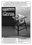
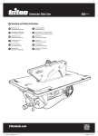
PTA 001
ASSEMBLY & OPERATING INSTRUCTIONS
For instructions
on the 184mm saw
supplied with this
product
see page 27.
Follow these instructions for correct assembly and operation of this product.
When you’ve finished setting up use some scrap material to work your way through the “Accuracy
Tests” and “Operation” sections, studying the manual before making the cuts.
If lending or passing on this product to someone else, ensure they also study this manual before
use.
NOTE: “Front of the Saw Table” refers to the end which has the switchbox. The “left-hand & righthand side” are when viewed from the front.
CONTENTS
PG#
Safety
3
Set-Up
Removing and Fitting the Legs (B & C)
Fitting the Saw Slot Insert (J)
Fitting the Trigger Strap (K)
Removing the Saw
Fitting the Saw Blade (N)
Fitting the Rip Fence (D)
Fitting the Overhead Guard (H & G)
Connecting the Power
Fitting the Storage Hooks (L)
4
4
4
5
5
5
6
6
7
7
Features & Functions
Rip Fence (D)
Protractor (F)
Captive Push-Stick
and Side Pressure Finger
The Overhead Guard (H)
8
8
9
10
12
Accuracy Tests
13
Trouble-shooting / Fine-Tuning
Cuts out of square
Workpiece jams
Adjusting the protractor pointer
15
15
16
16
Operation
Basic Ripping
Narrow Ripping
Ripping Long Pieces
Ripping Larger Sheets
Double Ripping
Planing an Edge
Planing a Face
Planing a Wide Sheet
Edge Rebating
Tongue and Grooving
Edge Work on Thin Material
Working on End-Grain
Taper Ripping
Cross-Cutting
Multiple Cross-Cutting
Multiple Cross-Cutting
against an End Stop
Halving Joints & Tenons
Mitre Cutting
Mitre Cutting Moulding
Mitre Cutting to a Length Stop
Cutting Sharp Points or Wedges
17
17
17
17
18
18
18
19
19
19
20
20
20
21
22
22
Optional Accessories
Bevel Ripping Guide
Wheel Kit
Router Kit
Mini Sliding Extension Table
Dust Bag & Collector
25
25
25
26
26
26
184mm Saw Instructions
Saw Safety
Saw Features and Functions
Fitting & Removing the Saw Blade
Adjusting Cut Depth
Bevel Adjustment
90˚ Check
Power Switch
Sighting the Cut Line
Saw Operation
Hand-Held Operation
Ripping
Saw Maintenance
27
28
29
29
29
30
29
30
31
31
31
31
32
PARTS LAYOUT
B Rear Legs (packed in Main Body)
C Front Legs (packed inside Rear Legs)
E Captive
Push-stick
F Protractor
(with Side Pressure
Finger)
D Rip Fence
J Saw Slot
Insert
A Main Body
L Storage
Hooks
22
23
23
24
24
25
H Overhead Guard
G Overhead Guard Support
I 184mm Power Saw
(fitted to Main Body)
N Blade
(packed
separately)
Page 2
K Trigger
Strap
SAFETY
- Observe the following rules at all times for safe, accurate work.
1. Never operate the saw hand-held while the
Trigger Strap (K) is fitted. To avoid the potential
for personal injury ensure the trigger strap is
removed before using the saw hand-held.
down to 80mm, removing 10mm. You could set the
fence at 7.5mm (allowing for a 2.5mm saw cut), but
you would be creating an uncontrolled narrow offcut
trapped between the blade and the fence, and it
could be flung out towards you.
2. Always keep fingers well clear of the blade.
Fit the overhead guard as low as possible, to just
allow the work to pass beneath. Make sure fingers
and thumbs are tucked in, and will not pass near
the blade even if the wood kicks or your hands slip.
It’s easier, safer and more accurate to set the fence
to your desired size (80mm) and keep good control
of it, allowing the offcut to fall harmlessly aside.
8. Always have the saw blade as low as possible.
You’ll get best results if you work with a lowered
saw blade. It is safer, and gives a smoother, less
splintered cut. You can also improve the quality of
your cuts by ripping slightly oversize (say 1 mm
more than you need) then re-setting the fence by 1
mm and making a finishing cut.
3. Never reach over or behind a spinning blade.
Most table saw accidents occur when operators
reach over an unguarded or poorly guarded blade
to remove off-cuts. Always use a stick to flick offcuts away, or preferably, switch off and wait until
the blade has stopped spinning.
4. Always use the safety guard when ripping.
The blade can lift the wood up and fling it towards
you with great force if the guard is not fitted. Do not
stand directly in line with the blade, and keep the
guard lowered so that the two anti-kickback
pressure fingers hold the work down on the table.
9. Always set the fence parallel to the blade, and
lock it securely at both ends.
You must never angle the fence to the blade. Your
wood will jam between the blade and the fence,
and could be flung out towards you.
10. Always prevent narrow off-cuts jamming in
the blade slot. Avoid creating thin off-cuts (say
around 1-2mm thick) on short pieces, as they could
become trapped in the table slot beside the blade
and could jam against the side of the blade.
5. Always use the captive push-stick and side
pressure finger when ripping narrow pieces.
It is important to keep control of the piece between
the blade and the fence - especially short pieces.
Use the captive push-stick rather than your fingers.
11. Ensure the saw slot insert (J) is correctly
fitted at all times. If damaged or functioning poorly,
cease operation until replaced.
6. Always use the rip fence when ripping.
Never attempt a freehand cut, for example following
a pencil line. The blade can fling the wood towards
you with great force if you twist the work even
slightly during the cut.
12. Always wear eye & ear protection.
Serious accidents can occur when operators get
sawdust or chips in their eyes during a cut. Use of
ear muffs, a dust mask and a dust collection system
are also highly recommended, especially when
using tools for prolonged periods.
7. Always try to have the larger part of the
workpiece between the blade and the fence.
Say for example you want to rip a 90mm wide piece
5.
6.
8.
4.
7.
Page 3
9.
11.
SET-UP
Removing and Fitting the Legs
Set up the unit in 1
a well-lit,
uncluttered
environment,
preferably on a
bench or table.
The front legs are stored inside the rear ones. Slide
the front legs out, as shown above. (Note that the
locking holes (shown) must align for leg storage.)
Plug the Rear Legs (B) 5
(with rubber feet) fully
into the sockets at the
rear of the unit (furthest
end from the switchbox). Plug the Front
Legs (C) (with plastic
foot plugs) in the front
panel sockets.
Release the lock
knobs inside the
rear panel by
rotating them.
Move the legs (B & C) sideways to disengage them
from the locking tabs.
Slide them out from their storage position.
2
Lock them by tightening
the round knobs.
3
Turn the unit right way up and test that all four feet
are sitting on the ground. Make any necessary
adjustments by extending one of the legs slightly
from its’ sockets to prevent the unit from rocking.
6
4
Locking
holes
Fitting the Saw Slot Insert (J)
1
Release the height lever on the saw and allow the
blade to drop beneath the table surface.
With the red plastic latch at the front of the saw slot
slid backward, insert the tabs at the front of the
saw slot insert (J) into the two cut-outs in the table
depression. Twist it slightly to engage the tabs on
either side of the insert. Push the latch forward to
lock it in position.
Raise the saw all the way up and re-lock the saws
height lever and remove the rubber band holding
back the saw guard.
Page 4
Fitting the Trigger Strap (K)
Never fit the trigger strap when using the saw hand-held.
Before fitting the Trigger Strap (K) always 1
ensure that the saw is not connected to
the power and that the switchbox is in
the “OFF” position.
2
K
Wrap the trigger strap around the
handgrip of the saw, with the hook & loop
side facing inwards.
K
Pass the end of the strap through the
buckle, until the security loop has passed
through.
Hold in the “lock-out” button on the saw
handle and engage the trigger while
tightening the strap back onto itself.
Ensure the trigger is locked fully “on”.
Removing the Saw (I)
Rest the saw table upside down on packers.
Release the saw height lever and pivot the saw
away from the baseplate so that all four clamp
knobs can be accessed.
2
1
Ensure the trigger strap is removed before
using the saw hand-held.
The clamp knobs have cut-away edges. When all four
cut-aways are facing the saw and correctly lined up,
the saw can be lifted straight out of the clamps.
The clamp bases will ensure the
saw returns to the same position
when re-fitted. Turn the knobs
clockwise about half a turn to
tighten the saw back down.
NOTE: Rotate the clamp knob
beneath the saw handle to allow
full adjustment depth of the saw
while clamped securely down.
Fitting the Saw Blade
1. With the saw removed from the saw table,
hold in the shaft lock button and use the saw
spanner to remove the arbor bolt - turn in the
direction of the blade rotation. The shaft will
turn slightly before locking, allowing the bolt
and outer arbor washer to be removed.
1
2. Hold the lower blade guard fully back and
carefully slide the blade through the baseplate
and position it onto the inner washer on the
shaft. The graphics should face out and the
arrow on the blade should point in the same
direction as the arrow on the guard.
Page 5
2
3
3. Refit the outer arbor washer and while
depressing the shaft lock button, tighten the
arbor bolt firmly into position - turn against the
direction of blade rotation. Ensure the blade
seats flush between the inner and outer washers
then tighten firmly with the spanner.
2
Refit the saw to the saw table and turn the saw
table upright.
Fitting the Rip Fence (D)
Unfold the arms
from beneath
the Rip Fence
(D).
1
The fence can be fitted on the right-hand side or
left-hand side of the blade, depending on the cut
you are making or your personal preference.
To set the fence on the right, slide the arms along
the fence tracks from the right hand side of the unit
(when viewed from the switchbox end). The taller
part of the fence should face the plastic insert in
the tabletop.
3
Fully raise the
fence lock
levers on the
end panels.
2
Fitting the Overhead Guard (H & G)
Pull back the red locking latch, and press the guard
support (G) into the table depression. If necessary
loosen the round knob on the guard (H) and slide it
to the top of the guard support.
The saw slot is made from machinable material
which can be replaced if significantly damaged. It
must only be removed when fitting the Router Kit.
3
1
G
H
H
G
Locking latch
Spin the blade by hand before connecting the
power to ensure the blade is not touching anything.
Try to wobble the 2
guard support
(G) to ensure it is
properly locked.
The red latch
should pop up
and be flush with
the table top
when locked.
Loosen the knob on the overhead guard (H) and
slide it up and down the guard support several
times to enable a freer sliding motion.
The teeth on your blade should be pointing in the
same direction as the etched symbols on the sides
of the guard (H).
Page 6
Connecting the Power
Make sure the switch is “OFF”, plug the saw into
the female lead extending from the switchbox.
Remove the tie from the saw power cord and
unravel it to remove any folds.
Before connecting the power, practice switching on
and off.
Do not raise the Stop Plate.
Press the power switch with your finger to switch
the power “ON”.
3
1
Bring power to the switchbox via a good quality
extension cord (minimum 10 Amp).
Tap the stop plate with your hand or thigh to switch
“OFF”.
4
2
Before switching on the power, make sure that
nothing is touching the saw blade, or is likely to
vibrate into it and that your hands are well clear of
the blade.
Fitting the Storage Hooks (L)
The Storage Hooks (L) enable temporary storage
of table accessories when not in use.
1
L
Fit them onto the left or right hand base tube by
opening them and clipping around the tube. The
tab should be facing out and pointing upwards, as
shown.
L
Page 7
FEATURES & FUNCTIONS
The Rip Fence (D)
The rip fence can be fitted to the left or right hand
side of the unit depending on which is most
comfortable, or to suit certain cuts or jigs.
1
You can vary the tension of the fence locking levers
if locking is too firm or too loose.
Adjust the Nyloc nut on the inside of each end
panel until you are satisfied with the tension of the
locking lever.
FENCE SET ON
THE RIGHT
3
Adjust Nyloc
nut tension
FENCE SET ON
THE LEFT
Outboard Support
By removing the fence (D) and replacing it upside
down, it can be used to provide effective outboard
support when crosscutting larger workpieces
against the protractor.
Calibration Settings
The metal pointer is used for sawing applications. It
has a 2.5mm wide notch which represents the kerf
(width of cut) of the blade. Align your scale reading
with the side of the notch closest to the fence.
4
Always sight down directly from above the notch to
avoid sighting errors.
The red scale indicators are only used when the
optional Router Kit is fitted.
Locking Lever
D
The fence is locked by depressing the front and
rear fence lock levers until they tighten firmly.
2
Secure a batten over the fence arms to create a
surface level with the table. (The batten should be
approximately 25mm thick, as shown, or rebated to
25mm thick.)
Fence Storage
The fence (D) can be stored upside down in its’
tracks, as shown above, when not in use.
Page 8
The Protractor (F)
With the sandpaper face forward (away from you)
guide the protractor strip into the slot at the front
panel (switchbox end), and slide the protractor fully
along the slot to check that it slides freely.
Locking the Protractor (F) from Sliding
The protractor (F) can be locked against sliding in
its’ slot, when using the Side Pressure Finger detailed below.
HINT: If necessary apply a spray lubricant into the
slot for a smoother sliding action.
Slide it partly out of the table slot, loosen the round
knob by about 8 turns and rotate the T-bolt 90
degrees, so it protrudes through the windows in the
strip.
1
4
F
F
Window
T-bolt
The Protractor (F) can be used in a trailing mode
(protractor behind the workpiece)...
2
Do up the knob about 6 turns, then slide the
protractor back along the slot to the desired
position and tighten the knob. Check that the
protractor is firmly locked in the slot.
5
...or a leading mode (protractor in front of the
workpiece).
3
Storage
When not in
use, the
protractor can
be hung from
one of the
storage hooks
(L) .
It allows a 250mm crosscut capacity in the trailing
mode and approximately 450mm in the leading
mode. If the material is narrow enough, the trailing
mode is preferred.
Page 9
6
L
The Captive Push-Stick and Side Pressure Finger
Side Pressure Finger
Prepare the protractor for locking (T-bolt across the
slot as in “The Protractor”) and fully extend the side
pressure finger.
The side pressure finger is on the inside face of the
protractor (F), and when extended presses your
wood against the fence, with the fence on the right
hand side of the blade.
4
The finger can be locked fully retracted...
1
F
F
Window
T-bolt
Side pressure
finger
retracted
Place the wood in position against the fence and
adjust the protractor angle until the finger presses
the wood against the fence. The finger should flex
a little, but avoid applying excessive pressure.
...or fully extended.
2
5
Side pressure
finger
extended
The finger is released by pressing the tabs, and
sliding sideways.
Adjust the position of the protractor in the slot until
the finger is about 25mm in front of the blade. Then
tighten the protractor knob, locking both the
protractor and the angle setting.
3
Tab
Tabs
6
Page 10
Captive Push-stick (E)
The Captive Push-stick (E) slides along the tracks
on the back face of the rip fence (D). The swingarm rests against the front face of the fence, and
should pivot freely.
Position the push-stick (E) with the swing arm
either raised up, or resting on top of the workpiece
in front of the overhead guard (H).
4
1
H
E
E
D
Swing-arm
As the end of the workpiece passes the captive
push-stick, the swing-arm will drop behind it,
allowing you to push the work through with your
fingers clear of the blade.
The lock direction of the swing-arm can be
reversed, depending on which side of the blade the
rip fence is used. To change the direction, press
the rocker switch firmly and the other red “stop” will
appear through the face.
2
5
Rocker
switch
“stop”
Storage
When not in use the captive push-stick (E) can be
hung from the storage hook (L) .
Use the “stop” which allows the swing arm to pivot
towards the blade, not away from it.
6
3
L
E
E
“stop”
Page 11
The Overhead Guard (H)
The overhead guard (H) has hold-down fingers to
prevent kick-back of the workpiece. Always ensure
the guard is lowered until the fingers flex a little,
and lightly press the workpiece down on the table.
1
2
Hold
down fingers
H
H
D
FENCE SET ON
THE RIGHT
3
The bolt and knob on the overhead guard can be
reversed, if necessary, to allow the rip fence (D) to
be adjusted closer to the blade when using the
fence on the left-hand side of the blade.
H
D
Page 12
FENCE SET ON
THE LEFT
ACCURACY TESTS
Checking your Square
Then flip the square over, press it against the
straight edge again, and move the blade to the line.
First check to see if your square is accurate. Many
are not, especially handyman quality adjustable
squares.
2
Use a board with an absolutely straight edge.
Press the handle (base) of the square firmly
against it, and use a sharp pencil or a utility knife to
trace the edge of the blade on the board.
1
Any error in your square is seen as doubled, and is
more clearly visible.
Crosscutting with the Protractor
Hold the base of the square against the edge
which was against the protractor face. If necessary
adjust the protractor angle slightly then reset the
protractor scale pointer as described in Troubleshooting (page 16).
Set up as described in “Features and Functions”,
then lower the safety guard (H) to just admit the
piece of wood. Check that the protractor (F) is set
at exactly “0”. Switch on the power. Hold the wood
firmly against the main face of the protractor, and
push down lightly with your other hand, as you feed
the wood smoothly into the blade.
1
2
G
H
Then hold the square against the face which was
on the table and adjust the angle of the saw blade
to the table. If necessary refer to Trouble-shooting
on page 15.
F
3
Push the protractor until the workpiece is past the
back of the blade, then switch off the power by
bumping the STOP plate with your thigh.
If the leading edge of the wood fouled the
overhead guard support (G), or if the back of the
blade re-cut or burnished the cut end, your saw is
mounted slightly crookedly. Check the saw
alignment, as described in the next section, then
repeat the test.
Page 13
Ripping Test
Take a straight piece of wood at least 70mm wide
and say 35mm thick. Place it flat on the table and
lower the overhead guard to just above the
workpiece.
2
Lock the rip fence exactly parallel to the blade with
a fence setting that will give you an off-cut of say
5mm [eg. 70mm wide wood less 3mm for the sawcut, less 5mm for the off-cut = 62mm].
E
1
H
H
Hold the base of your square against the face that
was on the table and check the cut.
3
E
D
Set up the captive push-stick (E) and side pressure
finger as described earlier. Switch on the power,
and feed the wood smoothly. Keep pushing it preferably without pausing - until it is fully past the
blade.
If the leading edge of the wood fouled the
overhead guard support (G), or if the back of the
blade re-cut or burnished the cut edge, check the
saw alignment and overhead guard support as
outlined in “Troubleshooting”, then repeat the test.
Keep fingers well away from the blade.
Page 14
TROUBLE-SHOOTING / FINE-TUNING
Cuts out of square
First check that the blade is square to the table and
make any necessary adjustments using the saws
bevel adjuster.
Loosen all 4 clamps knobs 2 full turns.
One at a time, release the nut with a 10mm
spanner, and slide each clamp toward or away
from the fence, as necessary until the blade skims
the fence when set at “0”.
1
4
Lock the fence at “0” and check that the teeth at
the front and rear of the blade lightly touch the
fence. If there is any misalignment, or the blade
prevents you from locking the fence at “0”, proceed
with the steps below.
5
2
Once satisfied with the alignment re-tighten the
nuts and turn the clamp knobs until they hold down
the baseplate of the saw.
With the fence set on (or near) “0” turn the unit
upside down and place it on packers or on a
bench, to prevent the fence and blade from
touching the ground.
Turn the unit right way up again and check that the
teeth at the front and rear of the blade lightly touch
the fence when set at “0”.
3
Page 15
Workpiece jams between the fence (D) and guard support (G)
Use an accurate square to check that the vertical
face of the rip fence is exactly square to the table
at both ends.
2
If necessary use a Philips-head screwdriver to
adjust the jacking and pivot screws until the fence
face is square.
1
pivot
screw
Loosen the knob on the overhead guard about one
turn, and remove it for the moment. Check that the
overhead guard support (G) is square to the table.
If not, lower the saw blade below the table then
bend the guard support square using a straight
piece of material.
Jacking
screw
3
If tightening the jacking screw, first loosen the pivot
screw. If loosening the jacking screw, then tighten
the pivot screw later.
When adjusting the screws ensure the fence arms
pivot firmly but freely, without wobbling.
G
Adjusting the protractor pointer
After performing several mitre cuts (as outlined in
“Mitre Cutting” on page 24) and you have
established the protractor position for a true 45˚,
adjust the degree pointer on the protractor by
prising it sideways with a screwdriver until it points
exactly to “0”.
1
Page 16
OPERATION
Basic Ripping
The rip fence (D) must be set parallel to the blade,
firmly locked at both ends, and the safety guard (H)
must be correctly lowered.
1
E
D
It’s always best to have the wider section between
the blade and the fence, as shown, so you can
keep good control over it with your hand(s) or with
the captive push-stick (E).
H
Avoid trapping narrow off-cuts between the blade
and the fence, and do not stand directly in line with
the blade in case an offcut shoots out towards you.
If the wood binds slightly between the overhead
guard support and the fence (D), you can increase
the rear fence setting slightly - around 1mm.
Narrow Ripping
If you want to rip a board into a number of identical
narrow strips, or if you want to set the fence closer
than 17mm to the blade, the safety guard will
prevent access for the fence and the captive pushstick.
1
Make up a notched pusher say 75mm wide, and
use it as shown with the side pressure finger. It will
enable the guard to be correctly lowered, while
creating access for the push-stick.
Ripping Long Pieces
When ripping long pieces which will overhang the
rear of the table by more than half their length,
either have a friend help you, or rig up a “tail-out”
support. The Triton Multi-Stand, shown, is perfectly
suited to this application.
1
Try to keep the workpiece moving, even slowly,
during a long rip. Pauses can cause slight steps in
the cut. A finishing cut, removing another 1mm,
should help if you need a completely smooth edge.
Page 17
Ripping Larger Sheets
Lock the rip fence firmly with the same reading at
both ends and adjust the overhead guard as low as
possible.
For ripping up to 450mm off very large sheets, use
one or two Triton Multi-Stands with a suitable
length of wood clamped in the head(s), to support
the offcut.
Push the workpiece against the fence and feed it
gently into the blade, keeping one hand on either
side of the work. Switch off with your thigh when
you finish the cut.
2
1
For ripping widths up to 1000mm, consider the
optional Mini Sliding Extension Table (see page
26). Alternatively, use the saw hand-held. Remove
the saw, disengage the trigger strap (K), and
check the operation of the saw guard. Clamp a
guide to the workpiece, which should be securely
supported off the floor on battens or packers.
Never do a free hand cut, following a pencil line.
It’s dangerous.
Double Ripping
You can double your maximum depth of cut by
turning the wood over, end for end, and making a
second cut. If the blade is exactly square to the table,
and if both edges of the wood are dressed square, the
two cuts should line up.
1
You won’t be able to use the safety guard for the first
cut, so be especially careful, and keep fingers well
clear of the blade area, even if your hands slip or the
wood kicks. Re-fit the guard for the second cut.
Use the captive push-stick and side pressure finger.
Make both cuts of similar depth: slightly over half the
depth of the workpiece.
This cut puts a lot of load on your saw and blade.
Never force a dull blade to cut. Slow down your
feed rate, and replace or sharpen the blade.
Planing an Edge
Keep the blade as low as possible and try not to
pause during the cut.
A tungsten carbide tipped blade or a planer blade
can give an excellent finish on poorly dressed,
weather-stained or painted material. It can also
remove any slight step left after double ripping.
1
Place the workpiece between the stationary blade
and the unlocked fence so it is lightly touching
them both. Fine-tune the fence position until the
scale readings at both end panels are the same.
Remove the workpiece and move the fence 1 or
2mm closer to the blade. Lock it off securely. Or,
simply measure the workpiece - say 90mm wide and set the fence at 88 or 89mm.
For planing a bowed workpiece, attach a straight
piece of scrap to the piece so it slightly overhangs
one edge for the full length. (Use strong doublesided tape, hot melt glue or brads.) Run the
straight piece along the fence. After dressing one
edge straight, remove the piece of scrap and run
the just-dressed edge against the fence.
Hold the workpiece against the fence and smoothly
push it past the blade, as shown. Use the captive
push-stick and side pressure finger to control the
workpiece, especially when planing narrow pieces.
Page 18
Planing a Face
If planing a face wider than your maximum depth of
cut, set up as described above, and make two
planing cuts, turning the workpiece over (end-for-end)
after the first cut. Use the side pressure finger and
captive push-stick to control the workpiece.
1
You won’t be able to use the safety guard for the first
cut, so be especially careful, and keep fingers well
clear of the blade area, even if your hands slip or the
wood kicks. Re-fit the guard for the second cut.
Try to make both cuts of similar depth. i.e. plane a
90mm wide face with two cuts of around 46mm deep.
Planing a Wide Sheet
Workpieces more than 450mm wide cannot be
passed between the blade and the fence. To
remove a small amount from large workpieces, do
not set the fence in close to the blade. Make up two
wooden sub-fences to attach to the rip fence in front
of and behind the blade, as shown.
1
Wooden
sub-fences
G
The front sub-fence must be narrower than the rear
one, by not more than one blade width. Drill suitable
sized holes in the face of your fence and attach the
sub-fences using screws or countersunk bolts, or
use strong double-sided tape. (2” carpet-laying tape
is ideal.)
Lock the rip fence so the rear sub-fence is exactly
flush with the left hand edge of the blade, as
shown. It acts as a “catcher” for the workpiece once
it comes past the overhead guard support (G).
For regular planing using such a jig, make up
several front sub-fences of different widths. Or just
make up one - say 1mm narrower than the rear
sub-fence - and make 3 passes to remove 3mm
from a wide sheet.
Edge Rebating
By lowering the saw blade and adjusting the fence,
you can make a wide variety of rebates.
To set the blade height,
mark the desired depth
of cut on a piece of
wood. Lay the piece
alongside the blade,
leaving both hands free
to adjust the saw blade
height.
2
When rebating
wood which is
rectangular in
profile always
make the first
cut with the
wood standing
on edge ...
1
... and the second
cut with the wood
lying flat.
You can’t use the overhead guard on edge rebates,
so be very careful with hand positions and ensure
that your fingers will be clear of the blade even if
they slip, or if the wood kicks.
Otherwise, if the
workpiece is a bit
narrow, it could
balance unsafely
on a narrow edge
after the second
cut.
Most rebates create a narrow off-cut. You should
avoid trapping the off-cut between the blade and
the fence. If you can’t avoid this, make sure you
are not standing directly behind the blade because
the off-cut could come spearing out towards you at
high speed, especially if it’s a short workpiece.
Page 19
3
Beware of trapped offcut
Tongue and Grooving
Study the previous section on Edge Rebating, and
then make two identical rebates from opposite
faces of the workpiece. This will leave you with a
central tongue.
2
Beware of trapped offcut
Always make the first two cuts into the narrower
edge of the workpiece ...
1
To make a matching, central groove, move the
fence outwards by one blade thickness, and make
two cuts from opposite faces. Then reset the fence
if necessary to machine out the waste between
your two cuts.
... and the two final cuts with the workpiece lying
down flat.
You cannot use the overhead guard, so be very
careful with your hand positions.
If you do the cuts in reverse order, your workpiece
will be left standing unsafely on the narrow tongue
after the fourth cut.
Test tongue & grooving settings on short off-cuts of
the wood you’ll be using.
Edge Work on Thin Material
If you want to rebate or groove very thin boards,
you will have to take some precautions, because
the workpiece could be unstable while standing on
it’s narrow edge.
1
Attach a suitable height sub-fence to the rip fence
to give extra vertical support to the workpiece. (See
“Planing a Wide Sheet” for attachment methods.).
If the width of the saw slot in the table also causes
a support problem, you may want to use a piece of
ply or hardboard with a thin slot in it for the blade,
securely taped to the table as a mask, as shown.
You cannot use the overhead guard so be very
careful with your hand positions.
Working on End-Grain
Attach a straight, wide board onto the rip fence for
extra vertical support. Use screws or bolts. Make
sure the working face is square to the table and
use packers between it and the fence to adjust if
necessary.
1
Make a captive “pusher” as shown, to slide along
the top of the board. Use it to support the
workpiece, and to hold it square to the table as you
push it past the blade. You may wish to clamp the
workpiece to the pusher.
Page 20
If making splined right-angled joints ... or splined butt joints...
2
3
... cut all pieces from opposite faces,
without changing the fence setting. This
will ensure the grooves line up.When
working with narrow wood, make sure
the workpiece cannot jam in the blade
slot (during or after the cut. You may
have to use a mask taped to the table
(as described in “Edge Work on Thin
Material”), or clamp the work to the
pusher.
Taper Ripping
To rip tapers, the workpiece must be angled to the
blade by a guide that travels parallel to the blade.
On long taper cuts, the protractor slider strip may
protrude beyond the rear of the table. For adequate
guidance ensure at least half of the strip is always
engaged in the slot.
Never angle the rip fence to the blade for taper
ripping. Taper cuts cannot be made in this way and
are extremely dangerous if attempted.
Another method, which is also suitable for longer
tapers, is to tack or tape a straight piece of scrap
onto the workpiece at the desired angle, and slide
the edge of the scrap against the fence, as shown.
There are three recommended methods. For tapers
up to approximately 750mm long, you can use the
protractor.
1
2
Scrap, attached to
workpiece, slides
against fence
If you regularly cut tapers of different angles, make
up an adjustable jig to angle the workpieces to the
blade. Two pieces can be hinged at the front and
then locked open at any desired taper angle. An
angled block holds the workpiece down, and
pushes it as the jig slides along the parallel fence.
Hold the workpiece tightly against the sandpaper
face and down on the table, as shown. Keep
fingers well clear of the blade. Make sure the
overhead guard is fitted and correctly lowered.
3
It is best to rehearse these cuts with the blade
dropped below the table level, in order to check
your hand positions throughout the cut.
The width of material you can handle is limited and
you may have to insert a packer between the
workpiece and the protractor face to achieve a
desired cutting line. The packer should either be
attached to the workpiece, (using double sided
tape, hot melt glue, or mechanical fasteners), or be
attached to the protractor face. Attaching to the
protractor face is best - especially when cutting
multiple pieces at the same angle. Glue a strip of
sandpaper to the working edge for extra grip.
Page 21
The jig must be slid
along the fence, set
parallel to the blade.
Cross-Cutting
When crosscutting, make sure the workpiece is of
a manageable length, and that both the workpiece
and the offcut you’ll create are well supported
during and after the cut.
Hold the wood firmly against the sandpaper face of
the protractor and down on the table while moving
it smoothly past the blade.
2 WRONG
With larger pieces, use a Triton Multi-Stand, and/or
reverse the fence and use a packer to support the
workpiece or the off-cut. (See Features &
Functions).
Do not use the fence as a stop unless
a spacer block is fitted. See “Multiple
Crosscutting” below.
Set the protractor at “0” and make sure the
overhead guard is correctly lowered.
1
Never set the fence as a stop The offcut trapped
between the blade and the fence is uncontrolled,
and will be flung out towards you, possibly causing
injury and damage.
Multiple Cross-Cutting
If you want to use the fence to crosscut a number
of short pieces to the same length, you must attach
a spacer at least 19mm thick to the front of the
fence using screws, tape, hot-melt glue or a Gclamp.
1
Pieces not
trapped against
fence
Set the fence to the desired length of the pieces,
plus the thickness of the spacer.
By using the spacer as a length stop, you don’t
have to individually measure, mark, and line up
each piece.
By ending the spacer before the front of the blade,
the cut-off pieces are not trapped between the
blade and the fence.
Multiple Cross-Cutting against an End Stop
1
Attach a straight sub-fence to the face of the
protractor, and clamp or screw a stop block to it.
Each piece pushed up against the block will be cut
to exactly the same length.
You can end the sub-fence at the side of the blade,
or you can extend it right across the table (provided
you make it out of a wider piece that you can
partly cut into without greatly weakening it.)
You can make the sub-fence up to around 900mm
long (longer if you have a Multi-Stand or reversed
fence for outboard support), and attach a tape
Page 22
Spacer
measure or a ruler to it, with “0” on the ruler being
flush with the edge of the blade. Use the ruler to
cut pieces accurately to length, or to set a stop
block.
2
Sub-fence
with stop
block fitted
When attaching a sub-fence to the protractor, it’s
best to use screws with suitable sized heads
through the keyholes in the protractor face. This
will enable easy fitting and removal, by just
loosening the screws and sliding the sub-fence
sideways.
Halving Joints & Tenons
Using the fence as a length stop is permitted when
cutting halving joints (rebates) and tenons,
because there is no offcut to be trapped between
the blade and the fence.
When tenoning, if you machine opposite faces, as
shown, without changing the blade height setting,
the tenons will all be perfectly central on the ends
of the pieces.
For rebates less than 450mm from the end, butt the
wood against the fence, and use the protractor as
shown to slide the wood. Make the outside
(defining) cuts using the fence and scales, then
make a series of cuts, moving away from the fence
by one blade-width after each cut.
If using a router to make the mortices, select the
cutter first (say 1/2” diameter) and make your tenons
1
/2” thick. The mortices will be easier - just a single
setup for your router.
2
Only move the wood sideways when fully clear
of the blade.
1
Mitre Cutting
With the protractor in the trailing position (for best
support of the workpiece) lock it at 45˚.
1
Make sure the protractor slides freely along the
slot. Hold the wood firmly against the face during
the cut - it will tend to “creep” sideways during a
mitre cut.
To test that you are set at exactly 45˚, cut about
250mm off the end of a straight piece of scrap. Fit
the pieces together and check with a square that
they form a perfect 90˚ right-angle.
If making any slight protractor adjustment, re-cut
both pieces, and check again.
Page 23
Once you have established a true protractor
adjustment, refer to “Trouble-shooting” (page 15) to
adjust the protractor pointer position.
3
If the wood is flat on both faces, cut the reverse
mitre at the other end by turning the piece end-forend, and lying it on it’s other face for the second
cut.
Mitre Cutting Moulding
Mouldings should always be cut with the flat base
resting against the table, and the taller edge
against the protractor. It gives better support, and
less splintering on the moulded visible faces,
because they were facing upwards where the cut is
always cleanest.
... and at -45˚, for the second cut.
2
If you can’t turn the workpiece over, (e.g. picture
framing or beading) cut the mitres with the
protractor set to +45˚ for the first cut...
1
When cutting flexible materials - such as thin
beading or moulding - the protractor face is too far
from the blade for adequate support, when the
protractor is set at negative angles. Attach a subfence to the protractor face, or insert a stiffer piece
of parallel scrap between the protractor and the
moulding, for back-up.
Mitre Cutting to a Length Stop
First crosscut your pieces to length, a small amount
longer than you’ll need. With the protractor carefully
set, at say +45˚, mitre cut one end of each piece.
1
For perfect length accuracy without measuring,
marking and sighting up each cut, fit a sub-fence to
the protractor, and clamp a mitred stop block to it for
the second cut, as shown.
Set the protractor to the reverse angle, -45˚, and cut
the other ends. All cuts are made with the moulded
face upwards (better support and less visible
splintering) and all pieces will be identical in length.
Grip the workpieces firmly because there is a
tendency for them to “creep” during the cut. Or glue
a sandpaper strip to the face of the sub-fence for
extra grip, if not using a stop block.
Page 24
Mitred corner against mitred stop block.
Cutting Sharp Points or Wedges
Sharp stakes, pegs or wedges can be safely cut using
the protractor - set at say 15˚ - and making two or four
cuts, turning the wood over after each cut.
You should use a sub-fence, because the protractor
face may not give sufficient support, especially when
cutting sharp points on stakes. Also your fingers might
have to pass too close to the blade for safety, without
a sub-fence.
Lower the saw blade to below table level and
rehearse this cut, without power, to confirm your
hand positions.
1
Glue sandpaper to the sub-fence for extra grip, or
attach a rear stop block to the sub-fence and butt each
workpiece up against it. Provided your workpieces are
all the same length, it ensures the points will be central
-without measuring, marking or sighting up - and
makes it easier and safer to hold the workpieces.
If the workpieces are too long to fit a stop block, use
sandpaper or clamps. Sight up cuts by using a line
squared around each workpiece - say 100mm in from
the end - reference it to a pencil mark on the sub-fence.
45 x 19mm material on edge is ideal for a sub-fence.
Rebate the end closest to the blade to allow the
overhead guard to adjust to 10mm above the table.
Adjust the overhead guard so the workpiece just
passes under it. Keep the blade as low as possible.
Sand-paper faced
sub-fence
Line-up reference mark
sub-fence and workpiece
Be careful of the small wedge-shaped off-cuts.
They can vibrate into the blade and become re-cut,
or flung out, or can wedge in the table slot beside
the blade. Keep a stick handy to move them away
from the blade after each cut.
If one becomes wedged in the slot, stop cutting,
switch off the power with your thigh, and wait until
the blade stops completely before withdrawing the
workpiece and removing the jammed off-cut.
OPTIONAL ACCESSORIES
Bevel Ripping Guide (BRA100)
The optional Triton Bevel Ripping Guide enables
accurate bevels and chamfers from 15˚ through 90˚,
and makes use of the protractor for perfect compound
mitres.
1
Wheel Kit (AWA100)
Add a pair of wheels for even greater portability.
1
2
Page 25
Router Kit (RKA 001)
The Router Kit enables you to fit a 1/2” or 1/4” router
to the Powered Saw Table for accurate and safe
moulding, planing, rebating and trenching cuts.
1
The kit comprises of a fully adjustable fence with
pressure fingers and a 3 piece guard (which can be
mounted directly to the table when the fence is not
used). A quick-fit mounting plate and table insert are
also supplied.
If the Router Kit is not stocked by your local retailer
they can order it in on request. Alternatively, it can be
ordered directly from Triton by phoning 1300 655 686.
Mini Sliding Extension Table (ETA100)
Fits quickly to the unit for a substantial increase in
capacity. 1000mm ripping capacity and 600mm
crosscut capacity. Sliding and fixed table operations.
1
Fully adjustable fence arrangement for added
versatility.
Folds to a convenient size for storage.
Dust Bag (DCA100) and Dust Collector (DCA300)
Fits to the unit for a for a cleaner, healthier work
environment.
1
Collects almost 100% of the saw dust created,
when vacuum cleaner is attached.
Page 26
TSA 184
184mm (71/4”)
Circular Saw
OPERATING & SAFETY INSTRUCTIONS
SPECIFICATIONS
Motor Size:
1600W
Blade Diameter:184mm (71/4”)
Arbour:
16mm
No load speed: 4800rpm
Cut depth:
90˚ - 63mm
(hand-held)
45˚ - 45m
Cut depth:
90˚ - 55mm
(saw table mounted)
IMPORTANT: Before operating, carefully read and understand all instructions
contained in this manual .
Save these instructions for future reference. If lending or passing on this product to
someone else, ensure that they also study these instructions carefully before use.
Due to our company policy of continuous product improvement, specifications may change without notice.
SAW SAFETY
- Carefully read the following warnings prior to operating the saw.
General Safety
1. Keep children and pets away. Do not allow
children, by-standers or animals to come near
the work area or to touch the saw or power lead.
2. Eye, ear and respiratory protection should
always be used with power tools.
3. Dress appropriately (eg. no loose fitting clothes,
neckties or jewellery, long hair should be tied
back, legs covered & footwear worn. Shirt
sleeves should be buttoned, or rolled up).
4. Guard against electric shock. Prevent body
contact with earthed or grounded surfaces (e.g.
puddles, pipes, radiators, cookers and
refrigerators). Consider using a E.L.C.B. (Earth
Leakage Circuit Breaker) for added electrical
safety.
5. Ensure you always operate on stable ground
with clear access to your work.
6. Never work in confined and/or low-lit areas.
7. Use a good quality extension lead, where
required. A heavy duty type, fully unwound,
should be used when working outdoors. Check
power leads regularly for damage. Faulty leads
should be replaced or repaired.
8. Do not subject the saw to excessive
dampness or humidity, or to an environment
where explosive or corrosive gases could be
present.
Saw Safety
1. Ensure the trigger strap is removed before
using the saw hand-held. Locking the trigger
“on” when using hand-held can be hazardous.
9. Do not force the saw. Adjust your feed rate to
allow the tool to run at its’ intended speed
without labouring.
2. Disconnect the saw from power and ensure
the blade has stop completely before making
adjustments. (ie. fitting or removing the saw
blade, fitting the trigger strap, mounting the saw
in the table or other maintenance work).
10. Do not apply lateral pressure on the blade or
in any other way attempt to slow down or forcibly
stop the blade from spinning.
11. Avoid removing off-cuts while the blade is
still spinning.
3. Ensure the blade retaining nut and depth &
angle adjusters are firmly tightened prior to
each use.
12. Avoid blade and/or arbor damage by ensuring
the saw guard has fully closed before setting the
saw down.
4. Do not remove or obstruct functioning of the
lower blade guard. Regularly check that it is in
good working order.
14. Only use 184mm (71/4”) blades, with a kerf
between 2.2 & 3.5mm, designed for circular saws
with a no-load speed rating of at least 4500rpm.
Never fit high speed steel blades or abrasive
discs (except Triton Sanding Discs).
5. Avoid accidental starting of the saw. Keep
fingers clear of the saw trigger until required.
6. Always have your workpiece securely
clamped. Do not attempt to hold the workpiece
in your hand while cutting. Keep both hands on
the saw handles.
15. Any damage should be repaired and carefully
inspected before use.
7. Keep hands away from cutting area and
blade. Use both hands and hold the saw firmly to
prevent loss of control. Do not place your hand
behind the saw blade as kickback could cause
the saw to jump backwards over your hand.
8. Do not over-reach or stand behind the cut
line. Adopt a stance where your limbs will be
safe even if the saw kicks back.
13. Do not use blades which are deformed or
damaged. Check the blade prior to each use.
16. Perform required saw maintenance and
adjustments according to the instructions.
Keep handles and switches dry, clean and free
from oil and grease.
17. Ensure the saw is disconnected from power
before leaving it unattended.
18. Store the saw in a dry location, out of the
reach of children.
Page 28
SAW FEATURES AND FUNCTIONS
WARNING! Disconnect the plug from the power source and remove the trigger strap (K) before
assembling, making any adjustments or changing accessories. Such preventive safety measures
reduce the risk of starting the tool accidentally.
Fitting & Removing the Saw Blade
1. Hold in the shaft lock button and use the saw
spanner supplied to remove the arbor bolt - turn
in the direction of the blade rotation. The shaft
will turn slightly before locking, allowing the bolt,
outer arbor washer and saw blade (if already
fitted) to be removed. If removing the blade,
carefully slide it out through the baseplate.
2
2. Hold the lower blade guard fully back and
carefully slide the blade through the baseplate
and position it onto the inner washer on the
shaft. The graphics should face out and the
arrow on the blade should point in the same
direction as the arrow on the guard.
3
1
3. Refit the outer arbor washer and while
depressing the shaft lock button, tighten the
arbor bolt firmly into position - turn against the
direction of blade rotation. Ensure the blade
seats flush between the inner and outer washers
then tighten firmly with the spanner.
Adjusting Cut Depth
Ensure the tool is disconnected from
power.
1
2
1
2
Loosen the depth adjustment lever and
pivot the saw body away from the
baseplate until the approximate depth is
achieved. Push down on the lever to
lock, but do not over-tighten.
For best cutting results the blade should
extend no more than one tooth depth
beyond the thickness of the material
being cut.
The height lever can be repositioned if
the mechanism is a bit firm or loose
with the lever raised.
To re-position the lever, prise off the
e-clip securing the lever with a blade
screwdriver. Remove the lever from the
hex nut and relocate it clockwise (if too
firm) or anti-clockwise (if too loose) one
position then refit.
E-clip
Replace the e-clip and re-check the
locking position of the lever.
Height
lever
Page 29
Bevel Adjustment
IMPORTANT: Do not attempt to bevel the saw
when mounted in the saw table.
1
Ensure the tool is disconnected from power.
Bevel angles can be set anywhere within the range
-0˚ to 50˚. Loosen the bevel adjuster at the front of
the saw then angle the saw body to the desired
degree setting, as marked on the quadrant.
Re-tighten the bevel adjuster.
90˚ Check
Ensure the tool is disconnected from power.
1
Set the saw to maximum cut depth. Set the bevel
adjuster to 0˚ on the quadrant.
Use a square to check that the blade is 90 degrees
to the saw baseplate, and make any necessary
bevel adjustments
Power Switch
IMPORTANT: Never use the trigger strap to lock
the trigger “ON” when using the saw hand-held. It
can remain fitted around the hand-grip of the saw,
allowing it to be slid into place when mounted to
the saw table.
2
Lock-out
button
1
With the lock-out button pressed in the trigger will
be free to pull “ON”. Releasing the trigger will switch
the tool “OFF”.
Ensure that both hands are firmly on the hand grips
of the tool before switching on.
Do not engage the blade with your workpiece until
it is spinning at full speed - likewise avoid switching
off the tool until the cut is complete.
Page 30
Sighting the Cut Line
The sighting indicators in front of the
saw blade provide guidance when
cutting along a pencil line.
1
2
For 90˚ cuts use the right hand
indicator and the left hand indicator
for 45˚ cuts.
The accuracy of the sighting
indicators can be adjusted using a
philips-head screwdriver.
90˚ cut indicator
45˚ cut indicator
SAW OPERATION
Hand-Held Operation
Rest the front of the baseplate on the workpiece
with your pencil mark aligned with the correct side
of the sighting notch. Ensure the blade is not
touching the workpiece.
Make sure the workpiece cannot move during the cut
- use clamps wherever possible. Never perform any
cuts on a workpiece held in the hand.
Large panels and long pieces must be well
supported close to both sides of the cut to avoid
pinching and kickback. Ensure the saw is positioned
with the wider part of the baseplate resting on the
larger piece, or on the piece with the best support.
Hold the saw firmly with both hands, and press the
trigger while holding in the lock-out button. When
the saw motor reaches full rotational speed, guide
the saw smoothly along the cut line.
1
2
Maintain a consistent feed rate - too fast may put
excessive strain on the motor, while too slow may
burnish your workpiece. Avoid any sudden
movements of the saw.
Prevent kickback by ensuring that you move the
saw in a straight line. Ensure that your blade is in
good order and that the cut does not close in on
the blade. (Use a small wedge or 3mm spacer in
the cut to prevent it closing if you’re cutting difficult
material). Release the trigger if the saw gives any
sign of stalling but do not remove the saw until the
blade stops spinning.
When cutting veneered board or wood less than
20mm thick, set the blade to protrude 5-10mm
through the work. This will reduce splintering.
When cutting thicker wood, set the blade to
maximum depth to reduce kickback.
Avoid cutting any nails, screws etc. by inspecting
your workpieces and removing any fasteners prior
to cutting.
Wherever possible, avoid free-hand cutting. It is
much safer and more accurate to cut with the saw
mounted in the saw table or guided by a clamped
on batten. Only consider using the saw free-hand
if, for some reason, it is not possible to perform the
cut on the saw table. If cutting free-hand, always
mark a straight cutting line and keep the saw from
wandering away from it.
If any unusual noise or odour occurs during
operation stop the saw immediately and contact
Triton.
Page 31
SAW MAINTENANCE -
Disconnect the saw from power before any maintenance
• Regularly check that the saw arbor and arbor
washers are clean, and free of built-up gum
deposits or caked-on saw dust. Check that the
faces of the arbor washers are smooth and free
from burrs. Check that the blade retaining bolt is
correctly tightened.
1
• Check the operation of the spring-loaded guard. It
must close quickly and without scraping
anywhere. Remove the blade and clean
accumulated saw dust or wood slivers from the
guard area using warm soapy water.
• The saw ventilation slots should be kept clean
and clear of any foreign matter. Use a lightly
dampened cloth to wipe the saw clean - do not
use solvents.
• Regularly check the saw blade for flatness. Use
of the saw with a buckled blade places excessive
load on the motor and gearbox assembly, and
may affect your warranty rights.
• Triton Manufacturing & Design Co. will not be
responsible for any damage or injury caused by
unauthorised repair of the saw or by mishandling
of the tool.
Brushes
• The carbon brushes are a consumable item
which should be inspected periodically and
replaced when worn.
1
• With the saw disconnected from power,
unscrew the brush caps located near the end of
the motor. Remove the brushes by pulling
carefully on the protruding springs.
If either of the brushes is worn to less than 6mm
long, they must both be replaced.
Saw Blade
• Regularly check that the blade is free from a build
up of gum resins or saw dust. If necessary clean
with a solvent such as WD40, RP7 or mineral
turpentine.
• The tungsten carbide teeth should be checked
regularly for sharpness and tooth breakages, and
repaired or replaced as required.
Triton Manufacturing & Design Co. AUSTRALIA
Ph: (03) 9584 6977 Fax: (03) 9584 5510
triton.com.au
Due to our company policy of continuous product improvement, specifications may change without prior notice.