1
LUCA
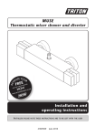
thermostatic bar mixer shower
86003100
Installation and
operating instructions
Installers
please note these instructions are to be left with the user
2180940C
April 2010
Thermostatic bar mixer shower
Contents
Page
MAIN COMPONENTS..................................................................... 1
INTRODUCTION..........................................................................2 - 3
TYPICAL DOMESTIC INSTALLATIONS............................................4 - 6
INSTALLATION..............................................................................7 - 9
Preparing the mixer valve............................................................... 7
Siting of the shower........................................................................ 7
Supply pipework............................................................................. 7
Variable fittings............................................................................... 8
Making good.................................................................................. 9
Fitting the mixer............................................................................. 9
FITTING THE MIXER CONTROLS.................................................... 10
Leak testing the mixer................................................................... 10
COMMISSIONING......................................................................... 11
Flow regulation.............................................................................. 11
To fit the flow regulator................................................................. 11
TEMPERATURE ADJUSTMENT RANGE............................................. 12
Recommended outlet temperatures - TMV2................................. 12
Adjusting the maximum temperature setting................................. 12
Operating the shower.................................................................... 13
Dimensions.................................................................................... 14
Spare parts ................................................................................15 - 16
APPROVALS................................................................................... 17
TMV2 REQUIREMENTS (12 MONTHLY VERIFICATION)................ 17
FLOW CHART................................................................................ 17
MAINTENANCE............................................................................. 18
Fault Finding...............................................................................19 - 20
Guarantee, service policy, etc....................................................rear cover
To check the product suitability for commercial and multiple installations, please contact Triton’s
specification advisory service before installation.
Telephone: 0844 980 0730
Facsimile: 0844 980 0744
E mail: [email protected]
Thermostatic bar mixer shower
Main components
Fig.1
C
C
A
B
A. Thermostatic bar mixer valve
B. Dogleg connector X2
C. Cover trim X2
All dimensions listed in this fitting book regarding the product and installation are approximate.
*All kits are for illustration purposes only and are not supplied unless otherwise stated.
Thermostatic bar mixer shower
INTRODUCTION
Water temperature requirements
This book contains all the necessary fitting and
operating instructions for your mixer shower.
Please read them carefully and read through
the whole of this book before beginning your
installation.
Recommended maximum:
= 65°C
Minimum hot water temperature:
= 55°C
Maximum cold water temperature: = 25°C
NOTE: Valves operating outside these conditions
cannot be guaranteed by the Scheme to operate
as Type 2 valves.
The shower installation must be carried out by
a suitably competent person and in sequence of
this instruction book.
A stored water temperature of 60°C is
considered sufficient to meet all normal
requirements and will minimise the effects of
scale in hard water areas.
Care taken during the installation will give a long
and trouble free life from your mixer shower.
SITE REQUIREMENTS
Water temperature adjustment and
thermal safety
The installation must be in accordance with
water supply (water fittings) regulation 1999
and/or local Bylaws.
The mixed water temperature can be adjusted
from cold through to a top limit which must
be preset during installation with full anti-scald
protection throughout the range (35°C to 40°C)
providing the hot water temperature at the inlet
remains 10°C above the outlet temperature.
Water pressure requirements
Running water pressure:
Low presure*
- 0.1 bar min.
Should there be a loss of flow to either incoming
supply then- water from the shower will stop or
be reduced until both supplies are restored.
1.0 bar max.
High pressure
- 0.5 bar min.
5.0 bar max.
SAFETY WARNINGS
Maximum static water pressure:
Low & High pressure
- 10 bar
a. DO NOT choose a position where the shower
could become frozen.
*This mixer shower is designed for high pressure
systems found in the UK, but can be installed
with low pressure gravity water systems with
reduced flow rates.
b. DO NOT connect this mixer shower to any
form of tap or fitting not recommended by
the manufacturer.
For effective operation of the internal seals, the
maximum static pressure must not be exceeded.
c. DO NOT allow the inlet pressure or flow
rates to operate outside the guidelines laid
out in ‘site requirements’.
Pressure reducing valve
d. DO NOT connect the mixer shower to a
gravity hot supply and a mains cold supply
(or vice versa).
On sites where the running pressure is above 5
bar, the use of a suitably sized pressure reducing
valve fitted in the cold mains supply pipe work
can provide nominally equal pressures at the
mixer shower.
Water minimum flow rate
For best performance within the specified running
pressure range a minimum flow of 8 litres per
minute should be available to both inlets.
Thermostatic bar mixer shower
PLUMBING REQUIREMENTS
Hard water areas
DO NOT use jointing compounds on any pipe
fittings for the installation,
a. If it is intended to operate the shower
in areas of hard water (above 200-ppm
temporary hardness), a scale inhibitor may
have to be fitted. For advice on the scale
inhibitor, please contact Customer Service.
DO NOT solder fittings near the mixer unit
as heat can transfer along the pipework and
damage the mixer valve.
b. For best performance the showerhead MUST be
regularly cleaned to remove scale and debris.
DO NOT subject the unit to a water temperature
above 80°C during installation, use, maintenance
or disinfection.
WATER SYSTEM REQUIREMENTS
IMPORTANT:
This mixer shower is suitable for:
• The layout and sizing of pipework MUST
be such that nominally equal inlet supply
pressures are achieved and the effects of
other draw-offs are minimised.
• Gravity water systems
• Pumped gravity systems.
• Fully modulating type combination boilers
• The pipe-work should be installed such
that other taps and appliances being
operated elsewhere on the premises do not
significantly affect the flow
• Multi-point hot water heaters.
• Thermal storage,
• Unvented systems
• When connecting pipe-work avoid using
tight 90° elbows; swept or formed bends will
give the best performance.
When installing this mixer with a Combination or
multi-point boiler, it may be necessary to install
flow regulation.
• The hot water pipe entry MUST be made to
the left-hand side inlet, marked HOT, ‘H’ or
with a red/orange label.
Check that the appliance is capable of delivering
hot water at a minimum switch-on flow rate
of 3 litres per minute. At flow rates between 3
and 8 litres per minute, the appliance MUST be
capable of raising the water temperature to 52°C
(minimum).
• Suitable isolating valves (complying with
Water Regulations and Bylaws) MUST be
fitted on the hot and cold water supplies
to the shower as an independent means
of isolating the water supplies should
maintenance or servicing be necessary.
Water temperature at the inlet of the mixer valve
MUST remain relatively constant when flow rate
adjustments are made (refer to the applianceoperating manual to confirm compatibility with
this mixer shower).
• It is preferable to flush the pipe-work to clear
the system of debris and check for leaks
before connecting to the mixer.
(Commercial applications)
Where thermal store systems and instantaneous
gas water heaters are used, if excessive drawoff take place the appliance may not be able to
maintain an adequate output temperature.
This could result in the shower temperature
becoming noticeably cooler.
• It is recommended that for all commercial
applications, easily accessible, in-line filters
are used to aid maintenance.
Flow regulators can be fitted with high-pressure
water systems to reduce flow rate and assist
economy.
• The mixer inlets contain removable filters
that may become blocked if debris is not
flushed through before fitting.
The hot supply temperature MUST remain a
minimum of 10°C hotter than the required blend
temperature for optimum performance.
Thermostatic bar mixer shower
TYPICAL DOMESTIC INSTALLATIONS
*(diagrammatic view – not to scale)
*Fig.2
Domestic gravity fed systems (fig.2)
The shower control MUST be fed from a cold
water cistern and hot water cylinder providing
nominally equal pressures. There MUST be
a minimum of one metre head of water. The
minimum head distance is measured from the
base of the cold water cistern to top of the
showerhead.
Stop valve
Cold supply
Cold water
cistern
Minimum head
If valves are gravity fed then supply pressure
should be verified to ensure conditions of use are
appropriate for the valve.
Gate
valve
Hot supply
Cold
water
mains
supply
Service
valves
Hot water
cylinder
Pumped gravity fed systems (fig.3)
Service
valves
The shower control MUST be fed from a cold
water cistern and hot water cylinder providing
nominally equal pressures.
Mixer
Drain
valve
Other
draw-offs
Draw-off must point down
to avoid airlock issues
The mixer unit may be used with a gravity fed
system with a pump to boost pressures as shown;
please refer to the pump installation guide to
establish the minimum head requirements for
automatic operation of the pump
Alternative supply
(must be below
vent pipe tee)
*(diagrammatic view – not to scale)
*Fig.3
Stop valve
Cold water
cistern
Cold supply
Minimum head
Alternative supply
(must be below
vent pipe tee)
Gate
valve
Cold
water
mains
supply
Hot
supply
Mixer
Hot water
cylinder
Service
valve
Drain
valve
Other
draw-offs
Service
valve
Pump
Isolating switch or
pull cord switch
(both fused at 3A)
Ring main
Draw-off must point
down to avoid airlock
issues
Thermostatic bar mixer shower
Instantaneous gas-heated systems,
e.g. combination boilers (fig.4)
*(diagrammatic view – not to scale)
*Fig.4
The shower control must be installed with a
multi-point gas water heater or combination
boiler of a fully modulating design (i.e.
to maintain relatively stable hot water
temperatures).
Mixer
A drop tight pressure reducing valve must
be fitted if the supply pressures exceed 5 bar
running.
Combination
boiler
Service
valves
An expansion vessel MAY be fitted, and regularly
maintained, to prevent the shower mixer
being damaged by excess pressures. This may
already be installed within the boiler (check with
manufacturer) and is in addition to the normally
larger central heating expansion vessel.
Hot water
CH flow
Expansion
vessel
Cold
mains
supply
Unvented mains pressure systems (fig.5)
Stop
tap
The shower control can be installed with an
unvented, stored hot water cylinder.
For systems with no cold water take off after the
appliance reducing valve, it will be necessary to
fit an additional drop tight pressure-reducing
valve when the mains pressure is over 5 bar. The
drop tight pressure reducing valve MUST be
set at the same value as the unvented package
pressure reducing valve.
Pressure
reducing valve
*(diagrammatic view – not to scale)
*Fig.5
Note: An additional expansion vessel may be
required if a second pressure-reducing valve is
installed. This does not apply to packages with a
cold take off after the pressure-reducing valve to
the cylinder.
CH return
Mixer
Safety devices
not shown
Service
valves
Unvented
hot water
storage unit
Expansion
vessel
Pressure
reducing valves
Balanced cold mains supply
Stop tap
Cold mains supply
Thermostatic bar mixer shower
Mains pressurised thermal store systems (fig.6)
*(diagrammatic view – not to scale)
*Fig.6
Packages of this type, fitted with a tempering
valve (blender valve) can be used. A drop tight
pressure reducing valve must be fitted if the
supply pressures exceed 5 bar running.
An expansion vessel must be fitted, and
regularly maintained, to ensure, the unit, is
not damaged by excess pressures. This may
already be installed externally or internally within
the thermal store (check with thermal store
manufacturer).
Mixer
Service
valves
Hot Blender
valve
water
Expansion
vessel
Pressure
reducing valve
Stop tap
Return
Flow
Boiler
Cold mains supply
Thermostatic bar mixer shower
INSTALLATION
*Fig.7
*(diagrammatic view – not to scale)
PREPARING THE MIXER VALVE
Check the contents to make sure all items are
present.
Before starting, make sure all of the openings on
the valve are carefully covered to stop ingress
of any debris, etc. while routing the supply
pipework.
The shower valve is suitable for exposed
installation onto:
• Solid wall
• Stud partition wall
• Dry lined wall
• Laminate cubicle or panel.
Showerhead can
be mounted
either side of the
mixer
Height of
showerhead
to suit user’s
requirements
SITING OF THE SHOWER & ACCESSORIES
Refer to (fig.7) for correct siting of the shower.
The mixer valve should be positioned, as
detailed, with all controls within comfortable
reach of the user.
The accessories (showerhead, riser rail and/or
fixed showerhead) can be positioned above or to
either side of the shower.
The valve must be installed in a position that
allows for easy access for future maintenance and
commissioning.
*IMPORTANT!
BEFORE FIXING the supply pipework within
the wall, refer to the ‘SUPPLY PIPE WORK’
and ‘VARIABLE FITTINGS’ sections.
See figures 8, 9 and 10 to ensure
the MINIMUM of 7mm of thread is
available once the cover trims are fitted.
*SUPPLY PIPE WORK
• Complete the pipework to the shower area
having decided on the position of the shower
and direction of pipe entry (for example
rising, falling or rear entry)
The hot and cold water pipes should be securely
attached within the wall or panel to support the
valve and prevent movement after installation.
THIS IS REQUIRED TO ALLOW THE
CORRECT FITTING OF THE MIXER VALVE.
Pipe fitting depth should be checked in
conjunction with the information given in
(fig.8) - a MINIMUM of 7mm of thread
MUST be available once the Variable Fitting is
secured into the wall end fitting and the cover
trim has been fitted. This is to allow the mixer to
be fitted correctly. Inlet pipe centres should be
approximately 150mm apart.
Thermostatic bar mixer shower
*VARIABLE FITTINGS
Fig.8
The supply pipes can be routed from the side,
rising, rear or falling and must end in suitable
fittings (fig.8) to accept the variable connectors.
The variable connectors can be used to connect
to ½” BSP female elbow fittings in solid wall
installations. The inlet centres on the variable
connectors have a degree of adjustment to allow
for misalignment of pipe work.
Appropriate
end fitting
The hot and cold supply pipes MUST be
anchored rigidly to support the valve and stop
any movement after installation.
Once the trim
is fitted, there
MUST be a
minimum of
7mm of thread
to allow the
mixer to be
fitted correctly.
Fig.9
7mm
Seal around
the variable
connectors
Thermostatic bar mixer shower
MAKING GOOD
Fig.10
• Make good the wall and complete the tiling.
Note: It is advised to use a suitable sealer around
the variable connector where it enters the wall to
stop water ingress (fig.9).
• Screw the supplied cover trims onto the
fittings until tight to the wall (fig.10).
FITTING THE MIXER
IMPORTANT: Make sure that all supply pipework
has been flushed through before fitting the mixer.
• Offer the shower valve up to the fittings.
• Check that the sealing washers are in place.
• Screw the unions onto the fittings.
• Fit the mixer controls (fig.11 & 12) and
carry out the commissioning procedure.
Thermostatic bar mixer shower
Fig.11
Maximum
temperature
stop
Fitting the mixer controls
The mixer controls will need to be fitted before
commissioning can be carried out.
Temperature control
• Fit the maximum temperature stop. The
orientation is shown in (fig.11).
Lower vertical
flat of the max
temp stop in
the 6 o’clock
position
• To fit the temperature control (right hand
side), position the temperature override
button in the 12 o’clock position. Once in
place, fit the retaining screw (fig.11).
Flow control - (fig.12)
• To fit the flow control (left hand side), the
flow control cartridge needs to be turned fully
clockwise until it stops.
Note: The flow control graphic (styles of this may
vary) should be positioned so that the front edge
of it is at the 12 o’clock position. The remainder
of the graphic should run towards you.
Temperature
override button
in the 12 o’clock
position
• If fitted correctly, the graphic and flow control
should now be sitting in the designed ‘OFF’
position.
• Once in place, fit the retaining screw.
• Do not fit the end trims until the
commissioning procedure has been carried
out and the temperature range checked.
Fig.12
LEAK TESTING THE MIXER
Front of
graphic in the
12 o’clock
position
IMPORTANT: Flush out the pipework in
accordance with Water Regulations and Bylaws.
• Fit the hose to the outlet (without the
showerhead fitted) and direct it towards the
waste outlet.
• Open the water isolating valves to the
shower and check for leaks.
• If any leaks are found, rectify them before
carrying out the commissioning procedure.
Turn the flow
control fully
clockwise
Flow control graphic
(style may vary)
10
Thermostatic bar mixer shower
COMMISSIONING
Fig.13
• Start the water flow by rotating the flow
control (left hand side) anticlockwise.
Mixer outlet
• Make sure that the hot and cold water
supplies are fully open and at (or near to)
their design temperature and pressures, and
are within the requirements as stated on
Page 2 & 14.
• Make sure the temperature control (right
hand side) is at the maximum temperature
setting WITHOUT operating the maximum
temperature override button.
Flow regulator
Flow regulator
• Allow the shower to run at this maximum
temperature setting until the water
temperature has stabilised.
Top
• Rotate the temperature control until your
desired ‘maximum temperature stop’
showering temperature is reached.
Water flow
Angled top
section
Note: the flow regulator must be fitted with the
angled top facing the outlet flow of water.
Note: If your desired temperature is above the
maximum temperature stop limit, please see
‘ADJUSTING THE MAXIMUM TEMPERATURE
STOP SETTING’ on Page 12.
• A final temperature check SHOULD be made
on-site to guarantee user safety, and that the
mixer falls within recommended ‘maximum
mixed water outlet temperatures’ - as stated
on Page 12.
FLOW REGULATION
A flow regulator is supplied for use with highpressure water systems. It may be fitted with
any of the systems listed to reduce flow rate and
assist economy.
TO FIT THE FLOW REGULATOR
Fit the flow regulator into the outlet fitting as
shown in (fig.13).
11
Thermostatic bar mixer shower
Temperature
override
button
Fig.14
TEMPERATURE ADJUSTMENT RANGE
The mixer has a temperature stop to prevent
accidental rotation to higher temperatures. This
is adjustable to provide a maximum temperature
of 35°C – 45°C.
The mixed water temperature can be adjusted
from cold through to a top limit (which can
be pre-set during installation – factory set
at approximately 38°C) with full anti-scald
protection throughout the range - SEE PAGE 17.
Recommended outlet temperatures
Fig.15
The BuildCert TMV scheme recommends the
following set maximum mixed water outlet
temperatures for use in all premises:
44°C - for bath fill but see notes below.
Temperature
spindle
41°C - for showers.
41°C - for washbasins.
38°C - for bidets.
The mixed water temperatures must never
exceed 46°C at terminal fitting.
The British Burns Association recommends 37 to
37.5°C as a comfortable bathing temperature
for children. In premises covered by the Care
Standards Act 2000, the maximum mixed water
outlet temperature is 43°C.
ADJUSTING THE MAXIMUM
TEMPERATURE STOP SETTING
• Remove the end trim from the temperature
control to allow access to the retaining
screw. Undo the retaining screw and pull the
temperature control off (fig.14).
• The maximum temperature stop does not
need to be removed.
• Turn the flow control to full flow. With a
steady flow running, adjust the temperature
spindle until the temperature is about 38°C
(fig.15).
• When the showering temperature is
satisfactory turn off the shower. Refit the
temperature control, making sure the override
button aligns to 12 o'clock.
• Secure the temperature control in place with
the screw and fit the trim.
12
Thermostatic bar mixer shower
Operating the shower
Fig.16
• To start the shower, rotate the flow control
(left-hand side) anti-clockwise. For maximum
flow, rotate the flow control anti-clockwise
until it stops.
To stop the water flow, rotate the flow
control clockwise until the water stops
flowing (fig.16).
• To adjust the water temperature, rotate
the temperature control (right-hand side),
clockwise for a cooler shower, or
anti-clockwise for a hotter shower (fig.17).
• To overcome the maximum temperature stop,
depress the temperature override button
(fig.17) on the temperature control and
rotate clockwise past the '38°C' position.
Flow control
CAUTION: Exposed metal and chromed surfaces
may become hot during use.
Fig.17
Temperature
override
button
Temperature
control
13
Thermostatic bar mixer shower
Dimensions
50mm
40mm
All dimensions listed in this fitting book regarding the product and installation are approximate.
14
180mm
150mm
1/2” BSP
280mm
3/4” BSP
Thermostatic bar mixer shower
Spare parts
4
1
5
6
2
1
3
6
Ref.Description
Part No.
1. Flow control & temperature
knobs
86003160
2. Flow control cartridge
83313730
3. Thermostatic cartridge
83313720
4. Trim pack
86001150
5. Non return valves (NRV)
83308470
6. Trim pack (knobs)
83314110
- Flow regulator
22011280
15
Thermostatic bar mixer shower
*Spare parts - bar mixer fittings
A
B
Ref.Description
Part No.
A. Bar bracket UNBMXBKT
B. Bar bracket (exposed) UNBMXFIXEX
C. Bar bracket (push-fit) UNBMXFIXBT
D. Straight connector
86001120
E. Dogleg connector
86001110
The bar mixer fittings can be purchased from
Customer Spares. Please check that they are
suitable for your installation requirements
before ordering.
C
D
E
* Not supplied unless otherwise stated
T00360
16
Thermostatic bar mixer shower
APPROVALS
This mixer valve is approved to the requirements of:
*BS EN 1111
*On pressures above 0.5 bar.
*WRAS
Designation: HP-S (high pressure shower only)
TMV2 REQUIREMENTS (12 MONTHLY VERIFICATION)
It is a requirement that all TMV2 approved valves shall be verified against the original set
temperature results once a year.
On installation and on a yearly basis please perform the following checks:
1. Cold water supply isolation test
Isolating the cold water supply to the TMV, wait for five seconds if water is still flowing check that
the temperature is below 46C.
If there is no significant change to the set outlet temperature (±2°C or less change from the
original settings) and the fail-safe shut off is functioning, then the valve is working correctly and
no further service work is required.
If there is a residual flow during the commissioning or the annual check this is acceptable
providing the temperature of the water seeping from the valve is no more than 2C above the
designated maximum mixed water outlet temperature setting of the valve.
Note:
Temperature readings should be taken at the normal flow rate after allowing for the system to stabilise.
The sensing part of the thermometer probe must be fully submerged in the water that is to be tested.
FLOW CHART
17
Thermostatic bar mixer shower
MAINTENANCE
Cleaning
The following maintenance procedure must
be carried out for commercial and health care
premises, but is not necessarily required for
domestic installations.
It is recommended that all products are cleaned
using warm, soapy water.
Maintenance of the unit is required to give
continued performance after installation and that
it continues to provide scald prevention.
Do not use abrasive or aggressive chemical
cleaning products as this may affect the product
surface finish and invalidate your guarantee.
Cleaning the filters (fig.A)
Note: a thermostatic mixing valve in need of
maintenance can be undetectable in normal use
and only becomes apparent when a disruption
occurs in the hot or cold water
supply temperatures or pressures.
It is advised that this should be carried out by a
qualified person.
It is a requirement that all TMV2 approved
valves shall be verified against the original set
temperature results once every 12 months.
• Remove the filter housing and disassemble.
a) Initially check the filters for debris once every
three months and clean if necessary.
• Turn off the water supplies before starting.
• To gain access to the filters remove the unit
from the inlet fittings.
• Wash the filters thoroughly under running
water, use a suitable brush to remove all debris.
• Reassemble and fit in reverse order.
b) Perform a thermal shut off test
every three months, and check the
maximum temperature setting. See the
‘Commissioning’ section for the details of
this test and readjustment of the maximum
temperature setting if required.
Note: the filter
housing is Left
hand thread.
‘O’ ring
c) If the maximum water temperature varies
by more than 2°C from the commissioned
setting then carry out the following checks
• Check the isolating valves are fully open.
• Check the internal surface for scaling.
If the body requires descaling then it should be
removed from the pipework to carry this work
out (all rubber parts MUST be removed before
descaling).
• Check the function of the non-return valves.
The non-return valves (NRVs) prevent cross-flow
between hot and cold supplies under unequal
pressure conditions. They are designed for long
life with no maintenance.
non-return valve
Filter
Filter housing
Fig.A
Disinfection
Where chlorine is used for the disinfection
of water systems all relevant guidelines and
approved codes of practice must be strictly
followed. Failure to comply with the relevant
guidelines and approved codes of practice may
invalidate your guarantee.
Note: the (NRV’s) will only operate in one direction
- water should be able to flow into the unit from the
inlets, but NOT back out through the inlets.
WARNING!
Do not use ‘powerful’ abrasive or
solvent cleaning fluids when cleaning the
shower as they may damage the fittings.
If these checks do not highlight the reason
for the temperature variation, then internal
components will require replacement - please see
the spare parts list.
18
Thermostatic bar mixer shower
FAULT FINDING
The following can be carried out by a competent person
Problem/Symptom Cause
1 Water too hot.
2 Water too cold.
Action/Cure
1.1 Temperature
control incorrectly
commissioned.
1.1.1Refer to commissioning section.
1.2 Not enough cold
water flowing through
shower.
1.2.1Reposition temperature control knob
1.3 Increase in the
ambient cold water
temperature.
1.3.1Reposition temperature control knob.
1.4 Cold water supply
blocked.
1.4.1Turn off the shower and consult a
competent plumber or contact
Customer Service.
1.5 High volume of cold
water drawn off
elsewhere.
1.5.1Reduce the simultaneous demand from
the supply.
2.1 Temperature control
incorrectly
commissioned.
2.1.1Refer to 'commissioning' section.
2.2 Not enough hot water
flowing through
shower.
2.2.1Reposition temperature control knob
2.3 Decrease in the
ambient cold water
temperature.
2.3.1Reposition temperature control knob
2.4 Insufficient hot water
supplies from the
heating system.
2.4.1Make sure heating appliance is set to
maximum or has sufficient stored hot water.
2.4.2Make sure heating appliance is igniting by
trying a hot water tap elsewhere.
2.5 Hot water supply
blocked or restricted.
2.5.1Turn off shower and consult a competent
plumber or contact Customer Service.
2.6 Flow regulator not
fitted (HP systems
only).
2.6.1Fit the supplied flow regulator (Page 11).
3 High water flow 3.1 Flow regulators not
and/or poor
fitted.
performance on a
mains fed system.
3.1.1Fit flow regulator (Page 11).
19
Thermostatic bar mixer shower
FAULT FINDING
Problem/Symptom Cause
Action/Cure
4 Water does
not flow or
shower pattern
collapses when
another outlet
is turned on.
4.1 Water supplies cut off.
4.1.1Check water elsewhere in house and if
necessary contact local water company.
4.2 Shower unit blocked.
4.2.1Inspect the inlet filters. Clean if necessary.
4.3 Blockage in pipework.
4.3.1Turn off the shower and consult a suitably
competent plumber.
4.4 Showerhead blocked.
4.4.1Clean showerhead.
4.5 System not capable
of supplying multiple
outlets at the same
time.
4.5.1Reduce the simultaneous demand.
4.5.2Make sure stop/service valves are fully
open.
4.5.3Check if sufficient water pressure.
The following is recommended for a professional qualified installer only
5 Water too cold.
5.1 Running pressure in
excess of maximum
recommended.
5.1.1Fit a pressure reducing valve.
6 Shower controls
noisy while in
use.
6.1 Running pressure in
excess of maximum
recommended.
6.1.1Fit a pressure reducing valve.
7 Shower will not
shut off.
7.1 Flow control cartridge
worn.
7.1.1Renew flow control cartridge.
20
Thermostatic bar mixer shower
21
UK SERVICE POLICY
TRITOn STandaRd GUaRanTEE
In the event of a product fault or complaint occurring, the
following procedure should be followed:
1. Telephone Customer Service on 0844 980 0750 having available,
your details including post code, the model number and power
rating of the product, together with the date of purchase.
2. Based on information given over the telephone, a Triton Customer
Service Advisor will attempt to diagnose the fault and confirm
whether a site visit from a qualified service engineer is required.
3. All products attended to by a Triton service engineer must
be installed in full accordance with the Triton installation
guide applicable to the product. (Every product pack contains
an installation guide, however, they can also be bought via our
Customer Service Spares Department).
4. Our engineer will require local parking and if a permit is required
this must be available to the engineer on arrival at the call.
5. It is essential that you or an appointed representative (who must
be over 18 years of age) is present for the duration of the service
engineer's visit. If the product is in guarantee you must produce
proof of purchase.
6. Where a call under the terms of guarantee has been booked and
the failure is not product related (i.e. scaling and furring, incorrect
water pressure, pressure relief device operation or electrical/
plumbing installation fault) a charge will be made. A charge will
also be issued if nobody is at home when the service engineer
calls or adequate parking/permit is not available.
7. If the product is no longer covered by the guarantee an up front
fixed fee will be charged before the site visit.
8. Should proof of purchase not be available on an “in-guarantee”
call, or should the service engineer find that the product is no
longer under guarantee, the engineer will charge the same
fixed price and the customer will be expected to pay the
engineer before he leaves. If payment is not made on the day an
administration charge will be added to the fixed charge.
9. If a debt is outstanding from a previous visit, or from any other
Triton purchase. Triton reserves the right to withhold service until
the debt has been settled.
10. Triton takes the health, safety and wellbeing of its employees very
seriously and expects customers to treat all staff members with
respect. Should any employee feel threatened or receive abuse,
either verbally or physically, Triton reserves the right to withhold
service and will support the employee with a legal prosecution.
Triton guarantee this product against all mechanical
defects arising from faulty workmanship or materials
for a period of five years for domestic use only, from
the date of purchase, provided that it has been
installed by a competent person in full accordance
with the fitting instructions.
Replacement Parts Policy
Availability: It is the policy of the manufacturer to maintain parts
availability for the duration of production and a period of five years
thereafter, in accordance with industry standards.
Spare parts are available via our website, www.tritonshowers.
co.uk, or by telephoning Triton Customer Service Spares Department.
Payment should be made by credit/debit card (excluding American
Express or Diners Card).
Any part found to be defective during this
guarantee period we undertake to repair or replace
at our option without charge so long as it has been
properly maintained and operated in accordance
with the operating instructions, and has not been
subject to misuse or damage.
This product must not be taken apart, modified or
repaired except by a person authorised by Triton.
This guarantee applies only to products installed
within the United Kingdom and does not apply to
products used commercially. This guarantee does
not affect your statutory rights.
What is not covered:
1. Breakdown due to: a) use other than domestic
use by you or your resident family; b) wilful act
or neglect; c) any malfunction resulting from the
incorrect use or quality of electricity, gas or water
or incorrect setting of controls; d) failure to install
in accordance with this installation guide.
2. Repair costs for damage caused by foreign
objects or substances.
3. Total loss of the product due to non-availability
of parts.
4. Compensation for loss of use of the product or
consequential loss of any kind.
5. Call out charges where no fault has been found
with the appliance.
6. Call out charges where the water supply cannot
be isolated, this includes consequential losses
arising from unserviceable supply valves.
7. The cost of repair or replacement of pressure
relief devices, showerheads, hoses, riser rails
and/or wall brackets, isolating switches, electrical
cable, fuses and/or circuit breakers or any other
accessories installed at the same time.
8. The cost of routine maintenance, adjustments,
overhaul modifications or loss or damage arising
therefrom, including the cost of repairing
damage, breakdown, malfunction caused by
corrosion, furring, pipe scaling, limescale, system
debris or frost.
Payment can also be made by pre-payment of a pro forma invoice by cheque or money order.
Customer Service:
Triton Showers
Triton Road
Nuneaton
Warwickshire CV11 4NR
Triton is a division of Norcros Group (Holdings) Limited
4-1-2010
% 0844 980 0750
%
Trade Installer Hotline:
0844 980 0730
Fax: 0844 980 0744
www.tritonshowers.co.uk
E-mail: [email protected]
TRITON reserve the right to change product specification without prior notice. E&OA. © TRITON SHOWERS 2010