1
Notes
Operation
If there is a residual flow during the commissioning or the annual verification (cold water
supply isolation test), then this is acceptable providing the temperature of the water seeping
o
from the valve is no more than 2 C above the designated maximum mixed water outlet
temperature setting of the valve.
The unit has a single control lever that turns the unit on and off and adjusts the temperature.
Turning the handle anti clockwise from the off position firstly gives cold water flow then
increases the temperature to the maximum set value.
Temperature readings should be taken at the normal flow rate after allowing for the system to
stabilise.
Maintenance
The sensing part of the thermometer probe must be fully submerged in the water that is to be
tested.
This product is designed to be easily serviced, it has integral isolation, integral hot water
flushing to pasteurise the mixed water chambers reducing the incidence bio film growth and
unions that allow the complete body to be removed for servicing in the workshop.
Any TMV that has been adjusted or serviced must be re-commissioned and re-tested in
accordance with the manufacturers' instructions.
The installation of thermostatic mixing valves must comply with the requirements of the Water
Supply (Water Fittings) Regulations 1999.
Specifications
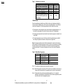
Minimum pressure drop through fitting for mixing
Dynamic pressure drop through fitting for mixing
Maximum static pressure to be applied to fitting
Maximum pressure loss ratio
Temperature stability with normal variation of
supply temperatures and pressures
Factory standard blend temperature
Maximum hot supply temperature
0.1 bar
5 bar
10 bar
20:1 either supply
Isolating and removal of the valve
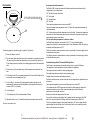
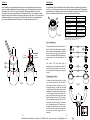
Using Fig.3 & 4 as a reference (page 6) The valve has integral isolation this is accessed by
unscrewing the shroud (54) and pulling it back along the elbow taking care not to scratch the
chrome, the 2.5mm hexagon wrench is inserted in the isolating plug and rotating it clockwise
until it locks. The securing nut (52) is then removed whilst supporting the valve to stop it
falling and damaging the surface below it. The valve can then be replaced or serviced as is
most convenient. The valve is replaced by reversing the above procedure ensuring the Oring is undamaged and in place.
Cleaning integral filters
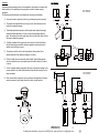
The integral filters are fitted into the inlet elbows to the fitting. The fitting should be removed
from the bases as described in the previous section the filters are then accessible for
servicing as shown in Fig3. They are a friction fit into the adaptors and should be care fully
prizes out washed and refitted. Failure to refit the filters may invalidate the guarantee.
± 2°C from set temperature
43°C
80°C
The sensitive wax capsule will shut down the operation of the valve if either the hot or cold
water supply fails, provided a minimum differential of 10°C exists between the mixed water
temperature and the remaining supply.
FLOW RATES
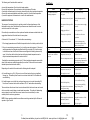
The flow rates (L/min) for the tap with and without flow limiters are quoted in the table below
Pressure Drop Bar
Low Pressure Flow Rate without Limiters
High Pressure Flow Rate with limiters
(Grey 6l Hot side &
Yellow 10l cold Side)
High Pressure that conforms to
BREEAM flow rate for Basin
Mixers < 6.0l/min at 3.0 Bar
Flow Rate with limiters
(Lime Green 2.75l Hot side &
Yellow 10l cold Side)
Supplied Factory Fitted
0.1
0.2
0.4
0.6
4.0
5.8
8.0
10.0 11.6
0.8
1.0
1.5
2.0 3.0 4.0
5.0
Not recommended, use flow
regulators as below.
Use Low Pressure
Setup
8.5
9
9.3
9
9
9
Use Low Pressure
Setup
4
4.3
4.6
4.9
4.8
4.8
5
10
For latest prices and delivery to your door visit MyTub Ltd - www.mytub.co.uk - [email protected]