1
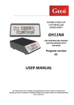
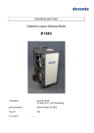
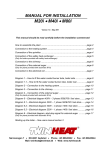
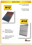
High-efficiency Condensing Boilers (60/100 mm Flue Outlet) Confeo Premix CP 24 HM GC Appliance No. 47-144-03 24 kW Central Heating Output 26 kW Domestic Hot Water Output Confeo Premix CP 30 HM GC Appliance No. 47-144-04 30 kW Central Heating Output 31 kW Domestic Hot Water Output USER OPERATING INSTRUCTIONS Veruk23308 PREFACE Confeo Premix high-efficiency condensing boilers have been designed to provide efficient, safe and comfortable central heating (CH) and domestic hot water (DHW). This section of the manual contains user’s operating instructions. Please read the instructions carefully before operating the boiler to maximise efficiency and benefit from the boilers specification . GUARANTEE & SERVICE ECA Heating UK guarantee this boiler for a period of up to 2 years from date of installation against manufacturing and material defect subject to the following terms & conditions. The guarantee consists of 1 year parts and labour warranty, which is extended to 2 years free of charge, provided the boiler is registered within 60 days of installation. Warranty registration cards may be returned by post, or register online at www.ecaheating.com to validate this warranty extension. Unregistered boilers are subject to a 1 year warranty or 2 years from date of manufacture which ever is the sooner. Installation must be in accordance with the installation and servicing instruction's, British standards and gas safety regulations. Benchmark Checklist page 56 of installation & service instruction's must be completed by your installer. Service and general maintenance must be carried out at least annually by a qualified Corgi registered engineer in UK or competent person in IE. This does not affect your statutory rights under UK or IE consumer law. The Benchmark Scheme ECA Heating is a licensed member of the Benchmark Scheme which aims to improve the standards of installation and commissioning of domestic heating and hot water systems in the UK and to encourage regular servicing to optimise safety, efficiency and performance. Benchmark is managed and promoted by the Heating and Hot water Industry Council. For more information visit www.centralheating.co.uk Please ensure that the installer has fully completed the Benchmark Checklist on page 56 of the installation instructions supplied with this product and that you have signed it to say that you have received a full and clear explanation of its operation. The installer is legally required to complete a commissioning checklist as a means of complying with the appropriate Building Regulations (England and Wales).All installations must be notified to Local Area Building Control either directly or through a Competent Persons Scheme. A Building Regulations Compliance Certificate will then be issued to the customer who should, on receipt, write the Notification Number on the Benchmark Checklist. This product should be serviced regularly to optimise its safety, efficiency and performance. The service engineer should complete the relevant Service Record on the Benchmark Checklist after each service. The Benchmark Checklist may be required in the event of any warranty work and as supporting documentation relating to home improvements in the optional documents section of the Home Information Pack. BOILER CONTROLS Control Panel 1 ON/OFF Switch 2 Display Panel: Blue Backlit LCD Display and 4 Yellow Status LED's 3 Central Heating (CH) Temperature Control Knob 4 Domestic Hot Water (DHW) Temperature Control Knob 5 Pressure Push-button 6 Reset Push-button / Burner LED 7 Control Panel Cover Fig 1 Operating The Boiler 1 Start Up / Shut Off The Boiler Turn the ON/OFF switch to ‘ ON ’ position. LCD display will turn ON and, Power-on sequence will be monitored for several seconds. After the power-on sequence is completed successfully, LCD display shows actual Central Heating (CH) flow temperature. Fig 2 Status LEDs CH / DHW when OFF indicate “stand-by” mode, no demand for DHW or CH. CH (Central Heating) Mode Fig 3 By adjusting the CH control knob, summer or winter mode can be selected. a) Summer mode Rotate the CH control knob to the ‘ ’ position. In this summer mode, CH mode is off, only DHW can be supplied. b) Winter mode Rotate the CH control knob to the ‘ ’ position. In the winter mode, your appliance satisfies central heating and also domestic hot water Fig 4 Fig 5 Adjust the CH water flow temperature between 30 oC and 80 oC with the CH control knob. The setpoint value appears on the LCD display when the left dot is flashing. After 10 seconds, actual CH water temperature will appear instead of the setpoint and left dot disappears. The boiler will modulate to the desired temperature. If a hot water tap is opened, DHW mode will interrupt the CH mode (hot water priority) until DHW requirement ceases . Fig 6 In case of failed ignition, automatic ignition sequence is repeated 3 times. If all ignition attempts fail, “ No flame signal” lockout occurs. The burner LED will turn RED and error code “ 4 ” will flash on the LCD display to indicate this error condition. Press the reset push-button to turn back the normal operation again. If the lockout condition continues after pressing the reset push-button, continue to page 6 for , Fault finding. Fig 7 DHW (Domestic Hot Water) Mode It is possible to have domestic hot water when: a) The appliance is in standby-by mode or, Fig 8 b) CH mode is active. DHW has priority over CH mode. Ensure control knob is not in DHW cancellation zone. Turn ON a hot tap to start DHW mode Turn OFF the hot tap to stop DHW mode. The boiler goes back to the previous mode. Fig 9 Domestic hot water temperature can be adjusted between 35 oC and 60 oC with the DHW control knob. The setpoint DHW temperature appears on the LCD display and left dot is flashing. (fig 9) After 10 seconds, actual CH water temperature will appear instead of the setpoint and left dot disappears. Boiler will modulate to the desired temperature (fig. 10). Fig 10 Comfort Mode (DHW Preheat function) / Economy Mode Comfort Mode maintains the DHW plate heat exchanger in a preheated condition dependent upon usage patterns to ensure fast delivery of hot water. Preheat cycle typically last less than 1 minute. In economy Mode DHW preheat function is cancelled. To select Comfort Mode, turn the DHW temperature control knob fully clockwise and then back to the desired DHW temperature setting within 3 seconds. Status LED Comfort mode will ON. Fig 11 To select economy mode, i.e. without DHW preheat, do the same action again (turn the DHW temperature control knob fully clockwise and then back to the desired DHW temperature setting within 3 seconds). Status LED Comfort mode will OFF. DHW Cancellation Function DHW mode has priority over CH mode, but DHW can be turned off. Turn DHW control knob (fig. 8) fully anti clockwise. In DHW cancellation zone, it is not possible to have domestic hot water even if a hot water tap is open. System Pressure Fig 12 System pressure should be within the range of 0.8 bar – 1.5 bar when boiler is cold (for outside this range, see below). This pressure will increase as the system becomes hot up to a maximum pressure of 3 bar. To check system pressure, on / off switch must be set to ON position. Depress button 5 (fig 1) system pressure will be displayed for 10 seconds. System Re-filling If water pressure falls below 0.6 bar, re-filling will be required, this is likely to occur if radiators are removed / vented or system leakage has occured. To re-fill 1. Turn DHW & CH control knobs fully anticlockwise. Leave on / off control knob switched on. 2. Locate your system filling loop. This is below your boiler on the right hand side, where the valves are. Fig 13 Filling tap 1 Removable pipe (A) with thump screws & washers Filling Tap 2 3. 4. 5. 6. Remove valve plug ends and fit temporary filling loop pipe (A) fig 13 Open taps 1 & 2 slowly and allow water to flow Press water pressure button on control panel and monitor pressure increase Fill when cold to approximately 1 bar. (cold range 0.6 – 1.5 bar) once reached turn off filling loop taps. If water goes over pressure, reduce by draining a small amount from heating system drain offs. 7. Remove filling loop copper pipe (A), refit plug ends and reset DHW & CH control knobs to required temperatures. Frost Protection The bolier will go on and off automatically dependant upon boiler water temperature to protect the water circuits against freezing. When the appliance is in stand-by mode if the system water temperature is less than 5 °C, the boiler starts as if there was a CH demand until 19 °C is reached. : The appliance must be on stand-by mode to activate frost protection system. Service Mode Service mode should only be used by a qualified engineer. Should the boiler be put into service mode accidentally, turn CH control to off position for 20 seconds then back to required temperature. If left service mode will terminate automatically after 10 minutes. Fig 14 User Self Help Fault Guide This guide is intended for user's self help only. For technical in depth fault finding please see installation & service instructions. Your Confeo Premix boiler has a built in self checking function and fault diagnosis display. These fault codes will help to interpret the nature of fault. Some faults conditions will be reset by pressing the Reset Push-button / Burner LED 6 (fig 1) which will be RED if a fault condition occurs or by an automatic reset if fault is corrected. Fault finding actions should only be under taken where user is competent to undertake. Table 1 Fault Display Remedy LED display not lit up Check on / off control knob is on. Check external fused switch is on. Are all house electrics on Replace 3 amp fuse in fused switch. No DHW when tap opened (LED display on) Ensure good flow from tap or try different tap. Make sure DHW knob is not set to DHW cancellation mode No Central Heating (LED display on) Turn CH control knob to maximum. Check external time clock and room thermostat are calling for heat. (set to maximum) No Central Heating DHW indication on Check if taps are running / leaking No CH or DHW Display shows 40 Low System Pressure Press pressure button, pressure must be at least 0.6 bar. If below follow re-filling instructions No CH or DHW – LED light red, display shows 4 Press Red LED to re-set, if fault code reappears. Check Gas supply is on and in credit Check Condensate drain is not blocked This is only a brief summary of the fault codes that may be displayed. In the event of other fault codes being displayed, please contact your installer to investigate if a system or product fault exists. ECA Warranty Service Helpline 0845 4637 803 Local Call rate charges apply Web self help www.ecaheating.com/selfhelp Registered Office - ECA Heating UK Ltd – 1 Bray Place, London SW3 3LL