1
•
•
•
•
•
•
•
•
Loosen the locking screw for the door handle, located on side of door handle spindle, using the key supplied. Do not
attempt to open door without loosening the locking screw. The locking screw prevents unauthorised access.
Open door using handle and remove contents packed inside stove, including front fire bar.
Install the Internal Deflector inside the stove body as shown on the accompanying drawings, using the bolts provided.
Install the Diverter Box to the rear of the stove body as shown on the drawings, using the bolts provided
Fit the Flue Closing Plate between the Flue Collar and the top of the stove body, with the opening towards the back, as
shown.
Insert burner through door aperture with the control valve to the right-hand side, and the pilot light to the front..
Manoeuvre burner so that the rear lugs fit over rear base plate, and the front lugs sit on front of the base plate. Secure
with the 2 bolts supplied with the burner.
Fix the stove down to the hearth, through the legs, using the screws and plugs provided.
CONNECTION TO THE CHIMNEY: Before you install the stove make sure the chimney flue outlet is correctly positioned
to align with the flue outlet on the stove and that the chimney is in good condition. If not, a chimney liner must be installed
or a suitable class 2 gas flue used. A draught is necessary to ensure the products of combustion are fully evacuated. The
stove must be installed in accordance with current gas and building regulations applicable. Connect and seal the stove
flue collar to the chimney using full depth of collar. A minimum of 610 mm (2ft) of vertical pipe should be established before the flue direction is changed, unless the stove is to be used with a fanned (powered) flue. The flue must have a minimum height of 3 mtrs (10ft), however to ensure optimum performance we recommend 3.66 mtrs (12ft) or higher. The flue
must be free of obstruction and any dampers must be fixed in a permanently open position. Ensure the chimney is not
closed and that it has been swept prior to the stove being installed. Make sure that rain, birds or any foreign body cannot
get into the chimney to cause damage or a blockage. This problem can normally be overcome by fitting an approved Gas
Cowl. It is essential to the effective running of your stove that the chimney draws properly to allow the products of combustion to escape.
GAS CONNECTION: The gas connection must be property sized to provide the correct gas rate at the required running
pressure at the valve inlet, and the final connection to the stove is to be completed with a suitable 8mm diameter gas pipe.
It is essential that a gas isolation tap is provided upstream of the stove, in a position that is easily accessible.
GAS PRESSURE: Make sure that there is adequate gas pressure and volume to the stove. The relevant pressures are on
the data plate. Ensure that the gas pressure to the stove is maintained when it is operating at the same time as other appliances in the building. The burner gas pressure can be obtained by unscrewing the pressure test nipple on the valve and
applying a suitable pressure gauge i.e. a manometer. Before the coals or logs are placed in position make sure that the
burner is operating correctly. The flame should be fairly even across the burner top.
VENTILATION: Under normal circumstances no additional room ventilation is needed.
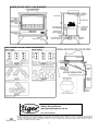
COALS OR LOGS LAYOUT: Refer to attached drawings
PRE-LIGHTING CHECKS
1. Ensure all the building work and flue sealing is complete.
2. Ensure the front fire bar is refitted in position.
3. Ensure all the coals or logs are correctly placed.
4. Close and secure the stove door.
5. Check that the stove door is completely sealed
6. Lock the stove door handle with the locking screw using key.
To the installation engineer: Please look at the section on stove lighting and commissioning and go through this with the
customer.
SECTION 2 - OPERATING INSTRUCTIONS FOR THE CUSTOMER
Please go through this section with the installation engineer so that you fully understand all the basic operating and maintenance procedures for your stove. The engineer will be happy to answer your questions and give you any help you may
need.
GENERAL NOTES: This stove is not for use with any solid fuels. It is only suitable for Natural (mains) Gas or LPG (liquid
petroleum gas) when the correct burner is fitted.
PLEASE REMEMBER THAT WHEN THE STOVE IS ALIGHT IT IS VERY HOT - EXCEPT FOR THE CONTROLS- NEVER TOUCH IT WITH YOUR BARE HANDS. The stove must not be touched when it is in operation. However, if you do
need to do so after it has been turned off and before it has completely cooled down (usually after about one hour) please
make sure that you wear stout oven gloves.
Flue Spillage Safety Monitoring Device- A Safety Cut-Off System: All stoves are fitted with an Oxygen Depletion Sensitive Pilot so that should the flue and/or chimney become blocked at any time the stove will automatically cut off. Normally
the pilot can be re-ignited after waiting about five minutes for the sensor to cool down. but in the event of the system tripping, have the flue and chimney checked by your installation engineer.
2