1
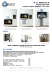
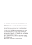
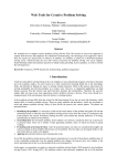
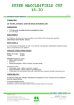
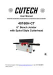
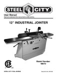
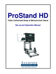
Operating Instructions
Millhog “Dictator XL”
OPERATING INSTRUCTIONS
FOR
MILLHOG DICTATOR XL
Mactech (Europe) Ltd, Unit 7, Scragg House, Langley Business Park, Langley Road, Langley,
Macclesfield, Cheshire, SK11 0DG TEL: +44 (0)1260 253846 FAX:+44 (0) 1260 251516
Web site: www.mactecheurope.co.uk Email: [email protected]
Operating Instructions
Millhog “Dictator XL”
OPERATING NOTE : Before using the Dictator XL machine operators
should read and be familiar with the document “Operating
Instructions Millhog Series 418 Dictator”.
The Gearbox Reducer should be fitted to the machine.
All safety and operating instructions in that manual apply to the
Dictator XL.
Contents
1. Operating Instructions
2. Clamp Rib and Pad Selector Chart
3. Parts List
1. Operating instructions
a. Identification of operating controls and their use
1. Feed wrench.
a. Used to advance and retract the cutting blade from the work.
2. Draw rod nut.
a. Activates draw rod and actuator.
3. Actuator.
a. Holds and aligns the clamp ribs and pads with mandrel.
4. Draw rod.
a. Connects the actuator and draw rod nut.
b. Turning draw rod nut clockwise pulls actuator towards
mandrel and expands clamp ribs and pads.
c. Turning draw rod nut counter-clockwise pushes actuator away
from mandrel and relaxes clamp ribs and pads.
5. Cutterhead
a. Rotates and holds the tool post.
6 Tool post
a. Locates cutting blade.
7. Cutting blade
a. Purpose: to machine end preparations on tube or pipe.
b. Consumable item, available in many sizes and configurations.
8. Blade lock
a. Secures the cutting blade to tool post.
9. Clamp ribs / pads
a. Secures tool to tube or pipe inside diameter.
b. Come in sets of three
c. Available in many sizes, see accompanying clamp rib chart.
10. Mandrel
a. Provides torque acceptance for entire tool.
b. Allows axial movement of tool.
c. Provides point of rotation for cutterhead.
Mactech (Europe) Ltd, Unit 7, Scragg House, Langley Business Park, Langley Road, Langley,
Macclesfield, Cheshire, SK11 0DG TEL: +44 (0)1260 253846 FAX:+44 (0) 1260 251516
Web site: www.mactecheurope.co.uk Email: [email protected]
Operating Instructions
Millhog “Dictator XL”
1. Operating instructions continued.
a. Identification of operating controls and their use:
11. Horizontal lifting ring.
a. For lifting tool horizontally.
12. Vertical lifting rings
a. For lifting tool vertically.
13. Nipple air inlet.
a. Accepts valved quick connect coupler for connecting air supply.
b. Always disconnect air supply before installing, changing or
securing cutting blades, adjusting, moving, or breaking down.
14. Air motor.
a. Provides power to gear head.
15. Gear head.
a. Rotates cutterhead.
b. Axially moves on mandrel
16. Mandrel Cap.
a. Fits over existing Mandrel.
b. Clamps in position on Mandrel
17. Actuator XL1.
a. Holds and aligns the clamp ribs and pads with mandrel.
(Consult Selector Chart)
18. Actuator XL2.
a. Holds and aligns the clamp ribs and pads with mandrel.
(Consult Selector Chart)
.
b. Selection of proper tooling
1. Clamp rib selection
a. Measure inside diameter of tube or pipe. Or using the outside
diameter and minimum wall thickness, calculate the inside
diameter.
b. Using the inside diameter and the accompanying clamp rib chart
select the proper clamp rib / pad set(s) and the appropriate actuator.
c. Please note clamp pads attach to clamp ribs. Clamp ribs can be
used without clamp pads.
2. Cutting blade selection
a. Measure the wall thickness of the tube or pipe.
b. Select a blade that is wider than the wall thickness.
c. Standard sizes are: 1/2”, 3/4” and 1”. Consult factory for other
widths.
d. Cutting blade configuration should be matched to your welding
specification.
e. Consult factory for special applications such as: counter boring,
seal weld removal , “J” preps, etc.
Mactech (Europe) Ltd, Unit 7, Scragg House, Langley Business Park, Langley Road, Langley,
Macclesfield, Cheshire, SK11 0DG TEL: +44 (0)1260 253846 FAX:+44 (0) 1260 251516
Web site: www.mactecheurope.co.uk Email: [email protected]
Operating Instructions
Millhog “Dictator XL”
1. Operating instructions continued.
c. Installation of proper tooling
1. Clamp rib installation.
a. Remove draw rod nut, and pull draw rod assembly from mandrel.
b. Fit the Mandrel Cap over the end of the Mandrel and secure with
setscrews.
c. Slide clamp ribs over the draw rod with the slotted end of the clamp
rib towards the actuator.
d. Insert the clamp rib slots into the slots on the actuator.
e. Inspect springs, replace if stretched or damaged.
f. There are two sets of clamp springs per set of clamp ribs.
g. Reassemble, insert draw rod assembly into mandrel and install
the draw rod nut.
2. Cutting blade removal and installation
a. Loosen blade lock screw(s), do not remove. If more than
one blade lock screw has to loosened they should be loosened
evenly.
b. Cutting blade must be slid to the outside of the cutterhead for
removal.
c. Insert new cutting blade from the outside of the cutterhead and
align so that the blade fully covers the tube or pipe wall.
d. Be sure to tighten all blade lock screws
d. Mounting the tool to the work
1. Using the feed wrench extend the mandrel all the way forward (this
moves clamp ribs away from cutterhead.
2. Retract the the mandrel two turns of the feed wrench.
3. Insert the clamp rib portion of the tool into the end of tube or pipe.
4. While positioning the cutting blade away, at least 1/4” from the work,
tighten the draw rod wrench.
5. Be sure cutterhead can rotate freely, without coming into contact
with the tube or pipe, when first starting tool.
e. Air connection
1. Use the hose supplied with the tool.
2. This hose has a valved quick connect coupler which will hold back all
air that is in the supply hose.
a. This feature allows the air supply to be safely removed from the
tool at any time.
3. Connect the air supply.
f. Operation of tool
1. Engage the ball valve, this will activate the tool.
2. Using the feed wrench advance the cutting blade towards the work.
3. Use a steady constant feed creating a continuous chip.
a. Using a constant feed allows the heat generated by the cutting
action to be removed by the chip. Heat build up is a primary
failure mode for cutting tools.
Mactech (Europe) Ltd, Unit 7, Scragg House, Langley Business Park, Langley Road, Langley,
Macclesfield, Cheshire, SK11 0DG TEL: +44 (0)1260 253846 FAX:+44 (0) 1260 251516
Web site: www.mactecheurope.co.uk Email: [email protected]
Operating Instructions
Millhog “Dictator XL”
3. Operating instructions, continued
f. Operation of tool
b. Engaging a rotating cutting blade with the work surface without
feed (rubbing), creates excessive heat build up.
4. When the desired end prep is accomplished, quickly reverse the feed
wrench by reversing the directional pawl, and retract the cutting blade
from the work.
5. Turn the ball valve off, so the motor no longer rotates the cutterhead, this
will stop the tool.
6. Disconnect the air supply.
7. Release the draw rod nut and remove the tool from the work.
Mactech (Europe) Ltd, Unit 7, Scragg House, Langley Business Park, Langley Road, Langley,
Macclesfield, Cheshire, SK11 0DG TEL: +44 (0)1260 253846 FAX:+44 (0) 1260 251516
Web site: www.mactecheurope.co.uk Email: [email protected]
Operating Instructions
Millhog “Dictator XL”
2. Clamp Rib and Pad Selector Chart
DICTATOR XL
PAD AND RIB SET WITH
XL1 ACTUATOR
ID RANGE INCHES
ID RANGE mm
D1 RIB
7.750" – 8.875"
196.8mm to 225.4mm
D2 RIB
8.750” – 9.875”
221.4mm to 250.8mm
D3 RIB
9.750” – 10.875”
247.6mm to 276.2mm
D2 RIB & D4 PAD
10.750” – 11.875”
298.4mm to 301.6mm
D3 RIB & D4 PAD
11.750” – 12.875”
298.4mm to 327.0mm
D2 RIB & D5 PAD
12.750” – 13.875”
323.8mm to 352.4mm
D3 RIB & D5 PAD
13.750” – 14.875”
349.2mm to 377.8mm
D2 RIB & D6 PAD
14.750” – 15.875”
374.6mm to 403.2mm
D3 RIB & D6 PAD
15.750” – 16.875”
400.0mm to 428.6mm
D2 RIB & D6 PAD & D7 PAD
16.750” – 17.875”
425.4mm to 454.0mm
D3 RIB & D6 PAD & D7 PAD
17.750” – 18.875”
450.8mm to 479.4mm
D2 RIB & D6 PAD & D8 PAD
18.750” – 19.875”
476.2mm to 504.8mm
D3 RIB & D6 PAD & D8 PAD
19.750” – 20.875”
501.6mm to 530.2mm
D2 RIB & D8 PAD & D9 PAD
20.500” – 21.500”
520.6mm to 519.1mm
D3 RIB & D8 PAD & D9 PAD
21.500” – 22.250”
519.1mm to 565.1mm
D2 RIB & D8 RIB & D10 PAD
22.125” – 23.125”
561.9mm to 587.3mm
D2 RIB & D8 RIB & D10 PAD
WITH XL2 ACTUATOR
22.625” – 23.625"
574.6mm to 600.0mm
Note that pipe sizes shown with green infill overlap with standard Dictator pipe sizes.
Refer to standard Dictator Operating and Maintenance Manual for range covered by the
standard machine.
Mactech (Europe) Ltd, Unit 7, Scragg House, Langley Business Park, Langley Road, Langley,
Macclesfield, Cheshire, SK11 0DG TEL: +44 (0)1260 253846 FAX:+44 (0) 1260 251516
Web site: www.mactecheurope.co.uk Email: [email protected]
Operating Instructions
Millhog “Dictator XL”
3. Parts List for Dictator XL
MO13173_011
Actuator 2
MO13173_014
Mandrel Cap
MO13173_015
Key
MO13173_016
Actuator 1
Mactech (Europe) Ltd, Unit 7, Scragg House, Langley Business Park, Langley Road, Langley,
Macclesfield, Cheshire, SK11 0DG TEL: +44 (0)1260 253846 FAX:+44 (0) 1260 251516
Web site: www.mactecheurope.co.uk Email: [email protected]