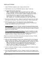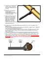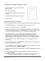
1
ProStand HD
Video Cutterhead Setup & Measurement Stand
Set up and Operation Manual
The contents of this document are protected by the copyright laws of the United
States of America. No part of this document may be reproduced by any means,
electronic or otherwise, without the expressed written permission of Accurate
Technology, Inc.
Copyright © 2007 Accurate Technology, Inc.
Revision D, ProStand 2.3, March 2008
Warranty
Accurate Technology, Inc. warrants ProStand™ against defective parts and
workmanship for one year, commencing from the date of original purchase. Upon
notification of a defect, Accurate Technology, Inc. shall have the option to repair or
replace any defective part. Such services shall be the customer's sole and exclusive
remedy. Expenses incidental to repair, maintenance, or replacement under warranty,
including those for labor and material, shall be borne by Accurate Technology, Inc.
Except as expressly provided in this warranty, Accurate Technology, Inc., does not
make any warranties with respect to the product, either expressed or implied, including
implied warranties of merchantability or fitness for a particular purpose, except as
expressly provided in this agreement.
Accurate Technology, Inc. shall not be liable for any special, incidental, or consequential
damages. Accurate Technology, Inc. shall not be liable for loss, damage or expense
directly or indirectly arising from the customer's use of or inability to use the equipment,
either separately or in combination with other equipment, or for personal injury, loss, or
destruction of other property, or from any other cause.
Accurate Technology, Inc.
270 Rutledge Rd. Unit E
Fletcher, North Carolina 28732 USA
800-233-580 828-654-7920
Fax 828-654-8824
www.proscale.com
[email protected]
ProStand 2.3
Accurate Technology, Inc.
Page 2 of 10
Overview
ProStand uses a color CCD camera coupled to a precision lens, a hairline crosshair, and a
color LCD display to locate and measure reference points, lines, and arcs on a cutterhead.
No measuring components make physical contact with the cutterhead thereby eliminating
common problems such as deflection errors or ambiguity of the exact point being measured.
The LCD shows a full color, real-time image of the cutterhead, including both the knife edge
and the supporting steel. Magnification of 22-25X allows an operator to see the smallest
defect in the knife edge or surface.
For the best accuracy and repeatability, the lenses’ focus must be adjusted to the correct
measuring plane. (The correct measuring plane is perpendicular to the lens and passes
through the center of the spindle/shaft.) After the focus is set, the maximum radius at any
point on the knife contour can be determined reliably and repeatedly. Radial and axial
measurements are taken by rotating the shaft until the knife edge comes into focus (on the
measuring plane).
Specifications
Measurement Range:
Radial measurements up to 190mm
Axial measurements up to 380mm
Dimensions (L x W x H):
900mm x 635mm x 1100mm
Weight:
Approx. 72kg
Optional Table
915mm x 610mm x 780mm
Input Power:
110-220VAC
Serial Interface:
RS-232 DB-9 connector
-connections for a computer OR a printer
Tools Required for Setup
Metric hex wrench set
SAE hex wrench set
ProStand 2.3
Accurate Technology, Inc.
Page 3 of 10
Setting up ProStand
1. Locate all ProStand components and a sample cutterhead shaft.
2. Check the bolts and screws on ProStand for tightness; tighten if necessary.
3. Assemble ProStand Table (if purchased).
NOTE: If the optional ProStand Table was not purchased, find a suitable
surface for ProStand. ProStand is designed to be used on tables with a height
of 750mm (30 inches). Be sure the table is capable of supporting the full weight
of the ProStand PLUS the weight of the heaviest cutterhead PLUS any
peripheral parts (such as a computer running the ProTool software, a printer,
tools, notepads, etc.). ProStand should be bolted to the table using M12 bolts.
4. Remove the two caps from the lens. Remove the cap from the camera (the silver spacer
must remain on the camera). Screw the lens into the camera. Tighten firmly by hand.
5. RS232 Connection (only one of the following connections should be made).
Use of a RS232 connection is not mandatory for simple operation of ProStand, but is
strongly recommended to maximize your investment.
Connect to a Printer: By default, ProStand is configured to operate with a printer via the
RS232 connection. Connect the supplied serial cable from the PRINTER CONNECTION
on the rear of the ProStand to the printer. (Only select thermal printer models will operate
properly with ProStand’s output.)
Connect to a computer to use the ProTool software: Connect the supplied serial cable
from the PROTOOL CONNECTION on the rear of the ProStand to the computer where
the ProTool will be installed. ProStand needs to be reconfigured to operate with a
computer connection, instead of a printer connection – see Page 10.
Follow the instructions on the ProTool CD to install and configure the software. Printable
ProTool manuals can be found on the ProTool CD.
6. Adjust the V-block spacing (left to right) to fit your cutterhead shaft (the shaft’s bearings
should rest firmly in the V-Blocks). To do this, remove the V-blocks, loosen the V-block
supports, and slide them (left to right) to the appropriate position. Re-attach the V-blocks.
Note: Some grinding shafts have a 30mm bearing on one end and a 62mm on
the other. These shafts are accommodated by inserting the included spacer
under the V-block that supports the 32mm end. If your grinder shaft requires a
different spacer, contact Accurate Technology directly.
7. Install the radial/axial handwheels, leaving a small gap between the handwheels and the
black housing (typically 1mm).
8. Plug in any ProStand peripherals (such as a computer, a printer, etc.) to a power source.
Plug in ProStand to a power source and turn on. Plug-in the monitor for ProStand and turn
on.
ProStand 2.3
Accurate Technology, Inc.
Page 4 of 10
9. Install the focus tool onto the
shaft as shown. Verify the
focus tool is perpendicular to
the shaft.
10. Rotate the shaft until the
FOCUS HERE plane (as
shown below) is parallel to the
surface of the table.
11. Note that the lens has two
adjustments, each with its
own lock. Ensure that the
upper lock is tight before
proceeding. (The upper
adjustment is set at the
factory and should not be changed unless instructed by an Accurate Technology
authorized technician.)
12. a. Adjust the lens’ focus (lower adjustment) until Point A is in focus, as shown in the
diagram below.
b. Turn the radial handwheel counter-clockwise until Point B is under the lens. Rotate the
cutterhead shaft to bring Point B into focus.
c. Turn the radial handwheel clockwise to return to Point A. Re-adjust the lenses’ focus.
d. Move back to Point B. Again, rotate the cutterhead shaft to bring Point B back into
focus (if necessary).
e. Repeat this procedure until the shaft does not need to be rotated to keep the tool in
focus. This process verifies that ProStand will repeatedly read the correct radius values.
Lock the lenses’ focus position so that it cannot be inadvertently moved. Remove the
focus tool from the shaft. (Note: Once this adjustment is made, the focus should not
be changed and this adjustment should not be repeated unless a different diameter
shaft will be used.)
POINT B
FOCUS
HERE
ProStand 2.3
Accurate Technology, Inc.
POINT A
FOCUS
HERE
SHAFT
Page 5 of 10
13. If the image on the LCD is not clear, place the supplied matt between the V-Block
supports (it may need to be trimmed to fit). This provides a greater contrast between the
knife and the background.
14. If the image is still poor, adjust nearby light sources, as too much or too little light might be
reflected into the lens. If there is too little light (entire image is dark), try adding a light
nearby. Placement of the entire ProStand may also remedy any light source problems.
15. Adjust the Radial axis so the center point of the crosshair is on the shaft’s edge. Move
from right to left along the shaft. If the center point of the crosshair does not stay on
the edge of the shaft, adjust the V-block positions (front to back) accordingly. Repeat this
procedure until the edge of the shaft remains on the crosshair.
16. With the center point of the crosshair still on the edge of the shaft, press the SELECT
key on the Digital Readout to activate the RADIAL display axis (the R next to the radial
measurement will begin flashing). Use the + and - keys to program the radius of the shaft
into the display. (Be sure to enter the radius of the shaft, NOT the diameter.)
ProStand 2.3
Accurate Technology, Inc.
Page 6 of 10
ProStand Operation
1. (For units equipped with a moving carriage) Slide the moving carriage to the front (nearest
the operator). The slide will snap into position.
2. Place the cutter to be measured onto the V-Blocks.
3. (For units equipped with a moving carriage) Slide the carriage back until it snaps into
place.
4. Line up the crosshair to the edge of the cutterhead. Press the SELECT key on the Digital
Readout to activate the AXIAL display axis and press “0” key. Adjust the axial and radial
position to view the point of interest on the cutterhead. The axial and radial positions are
shown on the Digital Readout. The current position information can now be printed (with
optional printer), sent to ProTool for data processing, or recorded as necessary.
HINT: In order to achieve the most consistent measurements, always approach the edge
or feature on the cutterhead from the same direction.
5. Once the features of a knife have been measured, the individual knives in a cutterhead
can also be compared to one another, to ensure proper alignment in both radial and axial
directions. This is accomplished by rotating the cutterhead until the next knife is in focus.
Note: Do not adjust the lens to bring the knife into focus. By rotating the
cutterhead to bring the knife edge into focus, measurement accuracy and
repeatability are maintained.
6. Inspect each knife (by following the cutting edge) for damage (chipping, etc) or temper
loss (bluing). The magnified image allows viewing of the knife that is not possible with the
naked eye or with a shadow.
7. Instructions for using the ProTool software can be found on its CD-ROM.
ProStand 2.3
Accurate Technology, Inc.
Page 7 of 10
Standard Functions of the ProStand Readout
POWER – Press the Power key to cycle the LCD display power on and off. When the display
is first powered on, a title screen appears, followed by the firmware version number.
Note: The Power key does not completely remove power from the readout.
MODE – Use this key to control the type of measurement units to be displayed. The types of
measurement units that can be displayed are as follows:
• millimeters/centimeters
• decimal inches
• 1/16in. fractions
• 1/32in. fractions
• 1/64in. fractions
Note: Fractions are disabled on ProStand. Metric readings are in millimeters by default.
SELECT - This key is used to select an axis to change its calibration. An axis is selected
when either the A (axial) or the R (radial) indicator is flashing. When selected, the PLUS,
MINUS, and ZERO keys are operational.
PLUS, ZERO, MINUS - These keys are used to change the calibration of the axial or radial
axes. An axis must be selected before these keys are active (see SELECT above).
F1, SEND, MON – Used for custom ProStand applications only.
PRINT – If a printer is connected directly to the ProStand, pressing the Print key generates a
label with the displayed axes & position(s), plus two blank lines. Note: The Tool Measurement
mode – especially helpful on ProStand – will generate a different label.
DISPLAY – Press this key to cycle through the available display modes. The following modes
are enabled from the factory:
• Show R axis ONLY
• Show A axis ONLY
• Show R and A axes at the same time
• Tool measurement Function – see next page for more information
• Arc measurement Function – see next page for more information
HOLD – Press this key to temporarily freeze the displayed positions of the axes. A “HOLD”
message will alternate with the displayed position of the axes when the hold mode is
activated. Press the HOLD key again to turn off the hold feature.
ABS/INC – This key is used to control the absolute or incremental measurement function of
each axis. By default, the readout measures in absolute mode. Press the ABS/INC key for
one second to set an incremental (temporary) zero point. Make an incremental measurement.
Press the ABS/INC key for 4 seconds to return to the absolute measurement mode.
This key is typically used to measure the error of axial or radial tooling alignment (see:
ProStand Operation Step 5). An axis must be selected before these keys are active (see
SELECT above).
ProStand 2.3
Accurate Technology, Inc.
Page 8 of 10
Advanced Functions of the ProStand Readout
Tool Measurement Function - This function allows an operator to locate and save an Axial
reference point on a knife, then locate and save a Radial reference point on a knife. The
saved measurement points are then displayed for review, can be compared to an engineering
drawing, or a label can be printed. To use this function:
1. Press the DISPLAY key until TOOL MEASUREMENT appears. Press the SELECT key to
begin a tool measurement.
2. A momentary message appears instructing the operator to locate the axial point of interest
on the tool. The current R and A positions are then displayed. Move the crosshair to the
point that represents the axial reference point of the tool. Press the SELECT key.
3. Another momentary message appears instructing the operator to locate the radial point of
interest on the tool. The current R and A positions are then displayed. Move the crosshair
to the point that represents the radial reference point of the tool. Press the SELECT key
when complete.
4. The saved radial and axial positions are displayed.
Press the PRINT key to print the saved positions onto a label. OR
Press the SELECT key to begin another Tool Measurement. OR
Press the DISPLAY key to exit this function.
Arc Measurement Function – This function allows an operator to measure the arc in a tool,
either for reverse engineering the tool, or for checking a tool against an engineering drawing.
To use this function:
1. Press the DISPLAY key until ARC MEASUREMENT appears. Press the SELECT key to
begin an arc measurement.
2. A momentary message appears instructing the operator to locate the first point on the arc.
The current R and A positions are then displayed. Move the crosshair to the first point on
the arc. Press the SELECT key when complete.
3. Another momentary message appears instructing the operator to locate the second point
along the arc. The current R and A positions are then displayed. Move the crosshair to the
second point on the arc. Press the SELECT key when complete.
4. Another momentary message appears instructing the operator to locate the third point
along the arc. The current R and A positions are then displayed. Move the crosshair to the
third point on the arc. Press the SELECT key when complete.
5. The arc radius is displayed. Press the SELECT key to continue.
6. The arc centerpoints are displayed. Notice that the measurements are followed by “CTR”
when the centerpoints are displayed. Press the SELECT key to continue.
7. The arc length is displayed.
Press the SELECT key to begin another Arc Measurement. OR
Press the DISPLAY key to exit this function.
ProStand 2.3
Accurate Technology, Inc.
Page 9 of 10
Drill Pattern for Bolting ProStand to a Table
1. Mark drilling locations onto your table using the
diagram at right.
2. Drill 4 holes through table.
3. Align ProStand’s threaded inserts to the holes on
the table.
4. Install M12 bolts (from the bottom of the table).
5. Tighten securely.
Using ProStand with a Computer
NOTE: The following instructions assume the computer will be running the ProTool software.
1. Turn ProStand’s power off – using the power switch on the rear of the unit.
2. If a printer is connected, disconnect it from ProStand.
3. Connect a serial cable to the connection labeled “ProTool Connect.” Connect the other
end of the cable to your computer. (If your computer does not have a serial port, either a
serial port card should be installed, or a serial-USB converter should be used.)
4. Turn ProStand’s power on. After the power up message and firmware version are
displayed, access the user programming mode: Press and hold the MODE key.
Momentarily press the ZERO key. Release the MODE key. A momentary message is
displayed: “Program Mode”, followed by instructions for using the Programming Mode.
5. Press the MODE key twice. The “Basic Parameters” menu title appears. Press the
SELECT key.
6. Press the MODE key 8 times. “Serial Baud Rate” appears. Press the PLUS key once to
change the displayed value to 19200.
7. Press the MODE key 2 times. “Serial Port Mode” appears. Press the MINUS key once to
change the displayed value to ProMUX 3 Support.
8. Press and hold the MODE key. Momentarily press the ZERO key two times. Release the
MODE key.
NOTE: The ProTool software will only operate properly with ProStand if the baud rate is
properly configured.
NOTE: The ProTool software will only operate with serial ports connected on COM 1 or 2.
Contact your computer administrator for assistance with this configuration.
ProStand 2.3
Accurate Technology, Inc.
Page 10 of 10