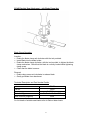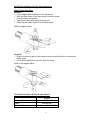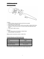
1
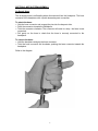
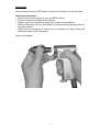
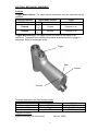
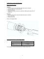
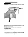
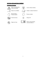
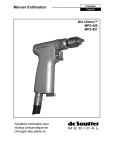
Operating Instructions
International
English
MultiDrive™
MPZ-450
MPZ-451
Pneumatic Modular Small
Bone Instrument System
DE SOUTTER MEDICAL MPZ INSTRUMENT SYSTEM
Index
Item ...................................................................................................... Page
Section 1: General Instructions ................................................................. 2
Warnings and Safety Rules ....................................................................... 2
Product Description ................................................................................... 2
Air Supply .................................................................................................. 2
Reprocessing Instructions.......................................................................... 4
Sterilization Accessory Part Number Details.............................................. 7
System Optional Accessories .................................................................... 7
Section 2: MPZ System Assembly ............................................................ 8
Air Supply Hose ......................................................................................... 8
Attachments ............................................................................................... 9
Section 3: MPZ Handpiece ..................................................................... 11
MPZ-450/451 controls ............................................................................. 11
Supplied Accessories .............................................................................. 11
Section 4: MPZ System Attachments ..................................................... 12
DZ-450 Drill & Burr Attachments.............................................................. 12
RZ-450 Reamer Attachments .................................................................. 14
SZ-450 Sagittal Saw Attachment ............................................................. 15
NZ-450 Quick Release Sagittal Saw Attachment .................................... 16
CZ-450 Reciprocating Saw Attachment ................................................... 17
CZ-451 Reciprocating Saw Attachment ................................................... 18
WZ-450 Wire Driver/PZ-450 Pin Driver Attachment ................................ 19
Section 5: Explanation Of Symbols......................................................... 21
Section 6: System Fault Finding ............................................................. 22
Conditions for Transport & Storage ......................................................... 22
Repair and Service Information ............................................................... 23
Guarantee and Liability ............................................................................ 23
0120
1
SECTION 1: GENERAL INSTRUCTIONS
Warnings & Safety Rules
Failure to follow these instructions may result in serious injury to the patient or
operating staff.
Do not attempt to use the equipment until all the instructions have been
studied and understood.
Never permit untrained personnel to use this instrument system.
Always operate the instrument at the correct air pressure as specified in these
instructions.
Always ensure that the hose is securely connected prior to use.
Always inspect all equipment and accessories before use. Do not use suspect,
damaged or worn equipment.
Always ensure accessories are correctly connected to the handpiece before use.
Always set the instrument mode selector to the SAFE position when changing
accessories or when not in use.
Always use eye protection when cutting to prevent injury from flying debris.
Do not allow loose articles to be caught by the moving parts of the instrument.
Never drop the instrument or it’s accessories; always handle with extreme care.
Always allow the instrument to stop before removing from the surgical site.
Only permit trained personnel to reprocess (clean and sterilize) this equipment.
Do not immerse the instrument in fluids.
Always use Stericut or De Soutter Medical approved accessories.
Never reuse items marked for single use, risks if reused include:
Cross contamination between patients,
Bone necrosis due to extra heat generation.
Inaccurate cutting
Product Description
The MPZ system is a modular pneumatic instrument system for small bone and
trauma surgery. The system consists of:
MPZ-450 The MPZ-450 Handpiece features a powerful reversible air motor, with a
trigger operated variable speed control.
MPZ-451 The MPZ-451 Handpiece features a powerful reversible air motor, with the
variable speed control operated by a separate foot pedal.
The Handpiece acts as the power plant for the MPZ system and may be fitted with
the following attachments:
DZ-450 - Drill Attachments
SZ-450 - Sagittal Saw Attachment
RZ-450 - Reamer Attachments
WZ-450 - Wire Driver Attachment
CZ-450 - Reciprocating Saw Attachment
PZ-450 – Pin Driver Attachment
NZ-450 – Quick Release Sagittal Saw Attachment
2
Air Supply
Use only 99.97% pure, dry compressed air or nitrogen filtered to 5 microns.
Lower pressures may be set for lower speed and torque requirements.
Monitor the pressure on the pressure gauge at the regulator.
Operating Pressure:
7 bar (100 psi)
Never exceed 7 bar (100psi) pressure.
3
Reprocessing Instructions
Warnings:
Limitations on
reprocessing:
Instructions
Point of Use
Containment
and
transportation:
Preparation for
cleaning:
Manual
Cleaning
Do not immerse the equipment in water other than when automatic
reprocessing, and only then, when fitted with the correct washing caps if
specified.
Do not exceed temperatures 140 °C.
Do not clean any part of the equipment in an ultrasonic cleaner.
Ensure that attachments with collet mechanisms are fully open when
reprocessing.
Long narrow cannulations and blind holes require particular attention
during cleaning.
Repeated processing has minimal effect on these instruments. End of life
is normally determined by wear or damage during use.
Detergents
Only use detergents that are declared by the manufacturer as safe for use
on anodised aluminium components.
Only use detergents with a maximum pH value of 11.0.
Ensure the detergent manufacturers guidelines are closely observed.
Do not operate the equipment while still warm
It is recommended that instruments be reprocessed immediately following
surgical use. The handling, collection and transportation of soiled
equipment should be strictly controlled to minimise risks.
Remove all attachments and accessories for cleaning, wash separately, or
dispose of as per instructions.
Equipment:
Manual cleaning should only be carried out where automatic
washer/disinfection is not available. It should be conducted in a dedicated
area by trained personnel wearing protective clothing e.g. gloves,
waterproof apron and goggles or visor. Use suitable detergents (See note
regarding detergents) and Nylon scrubbing brushes. Dedicated sinks with
temperature controlled water, ideally de-ionized or distilled and a Lint-free
cloth for drying.
Method:
1. Wash off excess contaminant with running water (maximum 35 °C)
avoiding fluid ingress via the air hose inlet. Scrub the components
thoroughly using a suitable detergent and nylon brushes to remove all
visible traces of contaminant. Pay attention to recesses, blind holes and
cannulations.
Note: Manually open and close chucks and blade clamps. Use suitable
nylon brushes to reach difficult surfaces and inside cannulations. Flush
through these areas to ensure any trapped contaminants are removed.
2. Rinse off all traces of the detergent with de ionized or distilled running
water (45-65 °C).
3. Shake off excess water and dry surfaces with a lint-free cloth.
4. Visually inspect each item to verify that all contaminants are removed in
accordance with local reprocessing guidelines.
4
Automatic
Cleaning
Equipment:
Automatic Washer/Disinfector capable of meeting relevant national and
international cleaning and disinfection standards i.e. ISO15883 OR
HTM2030.
Method:
1. Large contaminant deposits should be removed manually using the
method described in Manual Cleaning: - item 1. Pay particular attention
to recesses, blind holes, chucks, clamps and cannulations.
Note:
It is recommended that chucks be set to a middle position following the
above pre-wash. This facilitates the automatic washer/disinfection process.
2. Place the equipment onto the wire basket. Ensure all items are
separated. Ensure washing caps are securely fitted to the handpiece
and air supply hose if specified.
Note:
The placement of items in automatic washer/disinfector baskets can be a
critical factor in achieving effective cleaning. Selection of the basket type
and position of the items to be cleaned should be done by suitably trained
personnel in accordance with the manufacturer’s instructions for the
washer/disinfector.
3. Follow manufacturers loading instructions and select the appropriate
cycle recommended.
The cycle should include:
Pressurized cold water rinse (maximum 35 °C).
Hot water wash (minimum 55 °C). (See note regarding detergents)
Warm water rinse.
Disinfection rinse (minimum 80 °C for 1 minutes).
Drying cycle
4. Remove disinfected instruments from the washer/disinfector to a clean
area. Remove the washing caps and the sagittal saw blade clamp
washing spacer if fitted.
5. Visually inspect each item and verify the cleaning process is complete
and all contaminants have been removed in accordance with local
reprocessing guidelines.
Disinfection:
Maintenance:
Thermal disinfection is recommended and included in the automatic
washer/disinfection cycle. See above.
Lubrication of the pneumatic Handpiece motor is not essential but will
enhance the life and performance of the instrument.
1. Apply 3 drops of surgical instrument oil (part no. 30982- Non-sterile)
into the instrument air inlet after cleaning.
2. Connect the instrument to an air supply and run for at least 20 seconds
to ensure adequate dispersal of lubricant.
3. Lubricate collets, chucks and hose connectors using suitable mineral
oil.
5
Inspection and
Function
Testing:
Packaging:
Sterilization:
Storage:
Additional
Information:
Ensure the equipment is in good working order. Note any unusual sounds,
vibrations or operating speeds. If operating difficulties are experienced and
are not already covered in these operating instructions, refer to the Repair
and Servicing Information section of this manual.
Re useable cutting accessories (saw blades, drill bits, reamer shells etc.).
Inspect for damage and wear. Cutting edges should be sharp and free
from damage. Discard worn or damaged cutting accessories into a suitable
sharp’s disposal bin.
Single use accessories (Sterile saw blades, burrs, K wires etc.).
Accessories marked for single use only must not be re used. Dispose
of these items in a sharp’s bin or other suitable disposal method.
Place cleaned equipment into a Sterilisation case. If wrapping is used,
material conforming to EN868 allowing rapid penetration of steam should
be used.
Preferred Method.
• Vacuum steam autoclave, Wrapped or Unwrapped, minimum 3 minutes
@ 134°C (+3°C/ -0°C), 8 minute minimum drying time.
Other Validated methods.
• Gravity steam autoclave, wrapped 35 minutes at 134°C (+3°C/ -0°C), 8
minute minimum drying time.
• Gravity steam autoclave, wrapped 50 minutes at 121°C (+3°C/ -0°C), 8
minute minimum drying time.
Gravity steam autoclave, unwrapped 10 minutes at 134°C (+3°C/ -0°C), 8
minute minimum drying time.
Wrapping sterilized instruments in accordance with EN868 is
recommended to preserve sterility. The material should present a barrier
to microorganisms and particulate contamination.
Automated cleaning was validated in accordance with HTM 2030 using an
automated washer/disinfector and Neutral Ph enzymatic detergent.
Sterilization was validated in accordance with HTM2010 using a 134 °C
(+3°C/ -0°C) vacuum steam autoclave.
Note: Manual cleaning: Not validated for reasons of non-repeatability.
The instruction’s provided above have been validated by De Soutter Medical Ltd. as being capable of preparing a
device for re-use. It remains the responsibility of the reprocessor to ensure that the reprocessing as actually
performed using equipment; materials and personnel in the reprocessing facility achieve the desired result. This
normally requires validation and routine monitoring of the process. Likewise any deviation by the preprocessor
from the instructions provided should be properly evaluated for effectiveness and potential adverse
consequences.
Optional Accessories
Sterilization Accessories
6
Description:
Part No.
Handpiece Washing Cap
9950
Sterilisation Case Complete With Metal Tray
Metal Insert Tray Only
14390
14410
Case/tray will contain:-
Quantity
MPZ-450/451
EPV-200/201
Modular Handpiece
Dedicated Sagittal Saw Handpiece
1
1
Plus
Vaious
Various
Various
Air Supply Hose
MPZ System Handpiece Attachments
EPV System Handpiece Attachments
1
8
5
Other Optional Accessories
Air Supply Hoses
A wide selection of De Soutter Medical standard and ‘Wash Assist’ air hoses are
available to suit different connection systems, refer to the accessories brochure for
further information.
Foot Pedal Control –(MPZ-451 only)
Model
Inlet Connection Type
Part No.
FV-220
FV-221
MA7
Any De Soutter Medical Wash Assist Hose MPZ,
EPV, HST & DPZ With Suitable Hose Probe
Fitting
MA7
14900
14910
FV-222
7
15000
SECTION 2: MPZ SYSTEM ASSEMBLY
Air Supply Hose
The air supply hose is self-sealing when disconnected from the handpiece. The hose
connects to the handpiece with a quick release bayonet connection.
To attach the hose:
• Grip the hose connector and engage the pins into the bayonet slots.
• Push the connector towards the handpiece.
• Twist the connector clockwise. The connector will come to a stop - the hose is now
connected.
• Pull gently on the hose to check that the hose is securely connected to the
handpiece.
To remove the hose:
• Hold the handpiece and grip the hose connector.
• Twist the hose connector anti clockwise, pushing the hose connector towards the
handpiece.
Refer to the diagram.
8
Attachments
All the attachments for the MPZ system connect to the handpiece in the same way.
Attachment Connection:
• Ensure that the mode selector is set to the SAFE position.
• Grip the handpiece and attachment as shown.
• Align the slots on the attachment spigot with the pins in the handpiece.
• Push the attachment fully into the handpiece until the locking ring snaps back into
its original position.
• Check that the attachment is locked into the handpiece by gently pulling the
attachment away from the handpiece.
Refer to the diagram.
9
Attachment Removal:
• Ensure that the mode selector is set to the SAFE position.
• Grip the handpiece and attachment as shown.
• Using thumb and forefinger rotate the locking ring.
• When the locking ring reaches full rotation pull the attachment away from the
handpiece.
Do not drop the attachment out of the handpiece.
Refer to the diagram below.
10
SECTION 3: MPZ-450/451 HANDPIECE
Controls
Trigger Mode Selector: The mode selector determines how the instrument can be
operated:
Required Function
Off/ Safety
Trigger Mode Selector
O
Safety
Trigger
No function
Forward
Forward
Depress to run
Reverse
Reverse
Depress to run
Trigger (MPZ-450 only): The trigger controls the speed of the speed of the
instrument. The speed of the instrument increases progressively as the trigger is
depressed. Refer to the diagram below.
Trigger
Safe
Reverse
Forward
Technical Description and Part Number Details
Part No
Speed Control Type
Speed
MPZ-450
226414
Trigger
0-1100 rpm
Supplied Accessory
Surgical Instrument Oil (25ml bottle)
Part No. 30982
11
MPZ-451
226424
Foot Pedal
0-1100 rpm
SECTION 4: MPZ SYSTEM ATTACHMENTS
DZ-450 Drill & QZ-450 Burr Attachments
Chuck Operation
Universal (Jacobs):
Insert the drill bit into the chuck and tighten with the
chuck key.
Keyless:
Insert the drill bit into the chuck, grip the smaller chuck
ring and rotate the chuck body to tighten.
Note: Do not operate in reverse, as this will un-tighten
the chuck.
Quick Release
Pull the chuck sleeve back and insert the drill bit.
Rotate the drill bit until it enters the chuck fully.
Release the chuck sleeve.
Check that the drill bit is locked in the chuck by pulling
the drill bit away from the attachment.
Refer to the diagram below.
Supplied Accessories
DZ-450 Universal:
Chuck Key for 0-6.35mm Chuck
Chuck Key for 0-4mm Chuck
Part No. 30062
Part No. 8780
12
Technical Description & Part Number Details
Part 1
DZ-450
Quick Release
(AO)
DZ-450
Keyless
0 - 3.2
14130
0-1000 rpm
0-3.2mm
3.1mm
14140
0-1000 rpm
Quick
Release
Shank
1.9mm
DZ-450
Keyless
0.8 - 6.4
DZ-450
QuickRelease
(Trinkle)
Dz-450
Q/Release
(Hudson/
Zimmer)
Part No.
Speed
14120
0-1000 rpm
Chuck Capacity
0.8-6.4mm
Cannulation
Diameter
4.1mm
15050
0-1000
rpm
Quick
Release
Shank
4.1mm
15040
0-1000
rpm
Quick
Release
Shank
4.1mm
QZ-450
Q/Release
(Burr)
ISO
6360
15800
0-1600
rpm
Quick
Release
Shank
4.1mm
Part No.
Speed
Chuck Capacity
Cannulation
Diameter
DZ-450
Universal
0-6.35mm
(Jacobs)
14240
0-1000 rpm
0-6.35mm
DZ-450
Universal
0-4mm
(Jacobs)
14110
0-1000 rpm
0-4mm
4.1mm
2.4mm
Part 2
13
RZ-450 Reamer Attachments
Chuck Operation
Universal (Jacobs):
• Insert the drill bit into the chuck and tighten with the chuck key.
Hudson/Zimmer and AO:
The Hudson/Zimmer and AO reamer chucks operate in the same manner.
• Pull the chuck sleeve back and insert the reamer shaft.
• Rotate the reamer shaft until it enters the chuck fully.
• Release the chuck sleeve.
• Check that the reamer is locked in the chuck by pulling it away from the
attachment.
Refer to the diagram below.
Technical Description & Part Number Details
Part No.
RZ-450 Jacobs 0-6.4mm
14160
RZ-450 Hudson/Zimmer
14170
RZ-450 AO
14150
Cannulation
Diameter
Speed
4.1mm
0-300 rpm
Adaptor Chucks
Universal
(Jacobs)
Part No.
Hudson
Drive Part
No.
AO Drive
Part No.
Not Applicable
5440
7970
Zimmer Chuck
10060
5450
6590
Harris Chuck
10010
5460
6550
Hudson Chuck
10020
Not Available
6560
Trinkle Chuck
10240
7910
6580
AO Synthes Quick Release Drill
10280
5470
7980
AO Synthes/ Protec Reamer Chuck
10190
5480
Not Available
DIN 58 809 Reamer Chuck
10150
5490
6570
Not Available
11260
7770
Description
6.35mm Jacobs Chuck
DHS Chuck
14
SZ-450 Sagittal Saw Attachment – with Blade Clamp Nut
Blade Clamp Operation
Insertion:
• Rotate the blade clamp anti-clockwise with the tool provided.
• Insert Blade into the blade holder.
• Rotate the blade clamp clockwise, with the tool provided, to tighten the blade
clamp mechanism. Check that the blade is correctly located whilst tightening
clamp screw.
• Check that the blade is secure.
Removal
• Rotate clamp screw anti-clockwise to release blade.
• Gently pull blade from attachment
Technical Description and Part Number Details
Part No.
Speed
Blade Hub Type
Blade Wrench (Supplied)
SZ-450
14210
0-18000 cpm
De Soutter Medical S85
9590
For full details of suitable saw blades refer to Stericut data sheets.
15
NZ-450 Quick Release Sagittal Saw Attachment
Blade Clamp Operation
Insertion:
• Fit the Sagittal Saw attachment to the handpiece.
• With the blade clamp in the open position insert the blade.
• Push the blade clamp down.
• Tighten the blade clamp using the clamp nut.
• Check that the blade is secure in the blade clamp.
Refer to diagram below.
Removal:
• Grip the instrument and pull the clamp nut and turn anticlockwise to unscrew the
blade clamp.
• Lift the blade slightly and remove it from the clamp.
Refer to the diagram below.
Technical Description & Part Number Details
Part No.
Speed
Blade Hub Type
NZ-450
14230
0-21000 cpm
De Soutter Medical S88
16
CZ-450 Reciprocating Saw
Blade Clamp Operation
Insertion:
• Rotate the blade clamp anti-clockwise with the tool provided.
• Insert blade into the blade holder.
• Rotate the blade clamp clockwise, with the tool provided, to tighten blade clamp
mechanism. Check that the blade is correctly located whilst tightening clamp
screw.
• Check that the blade is secure.
Removal:
• Rotate clamp screw anti-clockwise to release blade.
• Gently pull blade from attachment
Never operate the attachment without a blade fitted.
Technical Description and Part Number Details
Part No.
Speed
Blade Hub Type
Rasp Shank Diameter
Blade Wrench (Supplied)
CZ-450
14220
0-7000 cpm
De Soutter Medical S92
1/8” (3.17mm)
9940
For full details of suitable saw blades refer to Stericut data sheets.
17
CZ-451 Reciprocating Saw Attachment
Blade Clamp Operation
Insertion:
• Grip the instrument and rotate the blade clamp sleeve clockwise.
• Insert the blade fully into the blade slot.
• Release the sleeve.
• Check that the blade is locked in by pulling the blade gently away from the
attachment.
Removal:
• Grip the instrument and rotate the blade clamp sleeve clockwise.
• Remove the blade.
• Release the sleeve.
Refer to the diagram below.
Technical Description & Part Number Details
CZ-451
15110
0-7000cpm
De Soutter Medical S22
Part No.
Speed
Blade Shank Type
For full details of suitable saw blades refer to Stericut data sheets.
18
`WZ-450
Wire Driver / PZ-450 Pin Driver Attachments
Wire/Pin Driver Controls
Actuating Lever: Pull the lever back to grip the wire/pin. Release the lever to release
the wire/pin.
Wire/Pin Driver Operation
Warning: The wire/pin must be clean before inserting into the instrument, even when
removing wire/pin from a fixation.
Warning: Do not use bent wires/pins.
Warning: Always fit a wire/pin guard when driving or removing wires/pins.
Fitting the Wire/Pin Guard:
• Grip the wire/pin guard and gently push it into the rear of the handpiece.
• The wire/pin guard will snap into place.
Wire/Pin Insertion:
• Set the trigger mode selector to safety/off.
• Insert the wire/pin into the front of the wire/pin driver to the required position. Do
not grip the actuating lever whilst inserting the wire/pin.
• Test that the driver is gripping the wire/pin correctly.
19
Wire/Pin Driving - Insertion:
• Set the Trigger Mode Selector to the required mode.
• Pull back the lever to grip the wire/pin.
• Depress the trigger(s) to rotate the wire/pin.
• Expose more wire/pin after penetration by releasing the top trigger and the
actuating lever, and sliding the instrument up the wire/pin. Repeat the driving
process.
• If the wire/pin is to be removed, do not trim the wire/pin less than 20mm
(¾”). 20mm must be protruding from the surgical site for the instrument to be able
to grip the wire/pin.
Wire/Pin Driving - Removal:
• Set the Trigger Mode Selector to the required mode.
• Slide the instrument over the exposed wire/pin.
• Pull back on the actuating lever to grip the wire/pin.
• Depress the trigger(s) to rotate the wire/pin in the required direction. Pull the
instrument away from the fixated site to remove the wire/pin.
• Take care not to bend the wire/pin during removal.
Immediately after use, clean the attachment to remove debris.
Technical Description & Part Number Details
WZ-450
14180
0-1000 rpm
1.8mm
0.6-1.8mm
Part No.
Speed
Cannulation Diameter
Acceptable wire diameters
PZ-450
14190
0-1000 rpm
3.2mm
1.8-3.2mm
Supplied Accessories
Cleaning Brush
Wire/Pin Guard
Part No. 8120
Part No. 9570
Optional Accessories
Diameter
0.7mm
150mm long
Sterile
K92-071
0.9mm
K92-091
1.1mm
K92-111
1.6mm
K92-161
All K-wires feature trocar points at both ends. Sterile packed K-wires are supplied in
boxes of 5.
20
SECTION 5: EXPLANATION OF SYMBOLS
Explanation of Symbols
Refer to the Operating
Instruction Manual
Vacuum Steam Sterilize.
Rotate to Lock Blade
Rotate to release Attachment
Speed Control /
Forward rotation
Reverse rotation
Do Not Immerse
2
Safety/ Off
Refer to the Operating
Instruction Manual
Single Use Only
21
SECTION 6: SYSTEM FAULT FINDING
Fault Finding
Fault:
Instrument does
not run.
Instrument runs
slowly, or seems to
lack power
Possible Cause:
Air supply faulty
Remedy:
Check air supply
Check hose connections
Trigger Mode Selector
set to Safety
Set Trigger Mode Selector to
Forward or Reverse.
Insufficient lubrication
Refer to Lubrication section of
manual
Insufficient air supply
pressure and/or flow rate
Check air supply pressure at
regulator (bottled air only).
Check hose for possible
restriction.
Regulator
malfunctioning.
Check air supply regulator.
Attachment will not
fit into handpiece.
Drive spindle misaligned.
Retry attachment assembly.
Accessory will not
fit into attachment
Debris inside chuck/
collet/ blade clamp
Clean with small brush
Accessory is damaged
Replace the accessory.
Do not force a damaged
accessory into the attachment
Instrument seems
to cut slowly
Worn accessory
Replace accessory.
• If any problem persists then contact De Soutter Medical Ltd.
22
Conditions for Transport & Storage
Temperature:
Relative Humidity:
Atmospheric Pressure:
Repair & Service Information
-20ºC to +40ºC
90% maximum.
1.5 atmospheres maximum.
All powered instruments and attachments should be periodically checked and
cleaned. Annual servicing is recommended for normal use. Due to the specialist
techniques used in the manufacture and maintenance of De Soutter instruments,
user servicing is not possible. For service and repair please contact your nearest De
Soutter Medical Authorized Service Centre.
To return an instrument for repair:
• Record the serial number of the instrument being returned. Enclose a brief
statement describing the reason for returning the instrument.
• Enclose the purchase order number for the instrument if warranty is being
claimed. It will be helpful to include a contact name.
• Pack the instrument securely and send to the address below.
Please ensure that the instrument has been properly decontaminated and sterilized.
Guarantee & Liability
De Soutter Medical guarantees all instruments, attachments and accessories to be
free from defects in material and workmanship for one year from the date of
purchase. De Soutter Medical is not liable by warranty or otherwise in the case of any
of the following:
• Abuse, misuse or use in other than a surgical environment;
• Disassembly, alteration or unauthorized repair;
• If the product has not been used in a reasonable manner and in full compliance
with the written instructions.
This guarantee does not affect your Statutory Rights in accordance with
1999/44/EEC
23
United Kingdom
De Soutter Medical Limited
Halton Brook Business Park
Weston Road
Aston Clinton
Bucks
HP22 5WF
United Kingdom
Tel:
+44 (0)1296 634 000
Fax:
+44 (0)1296 634 033
Email:
[email protected]
Internet: http://www.de-soutter.com
Australia
De Soutter Medical Australia Pty Ltd
2/12-14 Apollo Drive
Hallam
Victoria 3803
Australia
Tel:
+61 (0) 3 9702 4441
Fax:
+61 (0) 3 9702 4484
Email:
[email protected]
Österreich
De Soutter Medical Austria
Niederlassung Österreich
Hofkirchnergasse 3/1/30
A-3400 Klosterneuburg
Österreich
Tel:
+43 (0) 676 96 71 770
Fax:
+43 (0) 2243 21 656
Email:
[email protected]
Belgium
De Soutter Medical Belgium
In De Bruel 30
3620 Lanaken
Belgium
Tel:
+32 (0) 89/47 15 37
Fax:
+32 (0) 89/70 12 19
Email:
[email protected]
France
De Soutter Medical France
949 Avenue Park des Expositions
33260 La Teste de Buch
France
Tel:
+33 (0) 5 56 54 89 36
Fax:
+33 (0) 9 70 61 37 60
Email:
[email protected]
Deutschland
De Soutter Medical Germany
Niederlassung Deutschland
Kladenfloss
D-66625 Nohfelden
Germany
Italia
De Soutter Medical Italia
Palazzo Marco Polo
II Girasole
20084 Lacchiarella
Milano
Italia
Tel:
+39 (0) 2 9009 4098
Fax:
+39 (0) 2 9009 2673
Email:
[email protected]
Tel:
Fax:
Email:
+49 (0) 68 52-99 12 46
+49 (0) 68 52-99 12 47
[email protected]
Ref: 1957en- 1.6