1
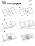
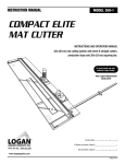
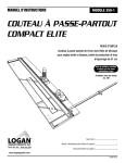
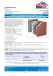
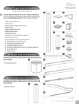
ENGINEERING
STRENGTH
I N S TA L L AT I O N M A N U A L
OUR STRENGTH IS OUR STRENGTH
RAFTER PREPERATION
‘A’ FRAME PREPERATION
AND
ASSEMBLY
‘A’ FRAME
PREPARATION
AND ASSEMBLY
RAFTER PREPARATION
..........................................................................................................................................................................................................................................................................
Open boxes, remove all main frame components and lay out
arranging rafters in numerical order.
Take ridge bar and
connect to fan assembly,
slide bracket into the
ridge and hook into the
pre-routed slot at the
back of the fan assembly.
Tighten ridge bracket
screw to secure in place.
N.B. Care should be taken to avoid damaging or scratching
components.
Choose an area of soft ground or use packaging materials.
STEP 1
Take ‘tie bar ’ rafters,
checking numbers to
ensure correct positioning
and connect as shown in
step 2.
Variable Coupler
STEP 1
........................................................................................................................
Take aluminium bracket and insert into each rafter and ensure that it
slides freely.
STEP 2
‘tie bar ’ rafters have
pre-cut slots on the inner
face to receive tie bar,
and a single hole at top
end to screw to fan.
It is easier to connect
them with ridge in upright
position as shown.
Ensure that numbers on
rafters correspond with
numbers on drawing.
STEP 2
........................................................................................................................
Check screw is located at the top of rafters but do not screw fully
home, allow hook brackets to slide in.
Secure rafter to ridge
bracket using 38mm
screw as shown.
N.B. This will be convenient later in the assembly process.
STEP 3
........................................................................................................................
STEP 3
Find conservatory roof drawing in box, and note the numbers and
positions of all components ie. Rafters, Ridge, Ringbeams.
Fit tie bar into slots in
underside of rafters and
screw through pre-drilled
hole in bottom of tie bar.
C
Components that are the same size will have the same number allocated
to them. The locations will be shown on the plan drawing.
STEP 4
2
Remember to fit seat
and caps to screws.
Screw length 50mm
STEP 4
............................................................................ .............................................................................................................................................................................................
...............................................................................................................................................................................
................................................................................................................................................................................
Use 45mm bolts with
caps through the
bar/rafter bracket.
STEP 5
Using 11/64” metal bit,
drill through pre-drilled
hole at top of rafter into
back of fan assembly.
Secure using 70mm
screw. Repeat on
other rafter.
STEP 6
Completed ‘A’ frame
should be set aside until
ring beam assembly
is complete.
STEP 7
When a conservatory has
a cantilevered hood the
rafters are connected in
much the same manner,
however it may be
necessary to support the
ridge on trestles during
assembly.
3
Cantilevered Hood
STEP 8
RING BEAM
ALTERNATIVE TIE BAR DESIGNS
ALTERNATIVE TIE BAR DESIGNS
STEP 1
Proceed to slide other
slotted rafter over lazer
bracket and ridge
bracket. Fix with top
screw as normal.
STEP 2
Slide aluminium gusset triangle over steel lazer
bracket.
STEP 3
Fix gusset from the
underside with screws
and cap.
STEP 4
..........................................................................................................................................................................................................................................................................
Slide steel lazer bracket
into slotted rafter and
locate onto ridge
bracket.
Rod Tie Bar
Locate corner ringbeam bracket into adjoining ringbeam.
Clip 2no L shaped cleats
simultaneously into the
slots provided in the
rafters .
STEP 1
STEP 1
.......................................................................................................................................
External Corner - Brackets come attached to ring beam.
Locate bracket and screw together through pre-drilled holes
using 50mm screws.
Slide tie bar end fixing
over the located cleats
and fix bolt.
STEP 2
STEP 2
.......................................................................................................................................
Fix ring beam to wall panels by drilling from underside and
screwing upwards.
Tighten nut onto bolt and
finish with bolt caps.
Again it is useful to tape ring beam and frames together
before drilling
STEP 3
STEP 3
.......................................................................................................................................
Install adjustable ring beam plate as shown
Tie bar is completed with
mild steel threaded bar
and PVC tubular cover.
4
..........................................................................................................................................................................................................................................................................
................................................................................................................................................................................
................................................................................................................................................................................
Lazer Tie Bar (Hidden)
RING BEAM
STEP 4
STEP 4
STEP 5
STEP 6
5
RAFTER ASSEMBLY
RAFTER ASSEMBLY
RAFTER ASSEMBLY
Sealock
Pin
Fit brackets into slots in
ridge (pre-cut), slide rafter
onto bracket and tighten
screw through pre-drilled
hole in rafter, locating into
angled section bracket.
Sealock
Pin
P402 Rafter
Tightening the screw will
pull the rafter tight.
P403 Used as Ridge
Centre Ridge
STEP 2
TOP BRACKET: Hook
bracket into pre-cut slot
in ridge (or fan assembly)
slide rafter onto bracket
and place screw through
pre-drilled hole in rafter
locating into angled
section of bracket.
No bracket is required
for the bottom
STEP 3
Screw to tighten rafter.
(38mm ss.)
STEP 4
..........................................................................................................................................................................................................................................................................
STEP 1
6
..........................................................................................................................................................................................................................................................................
.................................................................................................................................................................................
................................................................................................................................................................................
Lift completed ‘A’ frame
onto ring beam and prop
ridge against host wall.
RAFTER ASSEMBLY
Rafter fixed to adjustable aluminium flap with 50mm s.s. screw.
Slide rafter onto
adjustable ringbeam
Tip: Loosely fitting foam board internal liners can help locate rafters
into the correct position before screwing.
STEP 5
STEP 9
.......................................................................................................................................
Fit double sided tape holder (P.V.C.) to adjustable flap of ring beam.
Tape Holder
Foamboard
Adjustable Ringbeam Flap.
PVCu Liner
Aluminium
Ringbeam
Section Through
Adjustable Ringbeam
Ogee Gutter
PVCu Fascia
STEP 6
STEP 10
.......................................................................................................................................
Ring beam with
‘A’ - Frame and host wall
rafters fitted.
Fix foam P.V.C. inner liner board to adjustable flap with silicone
(use sparingly).
STEP 7
STEP 11
Add all rafters
.......................................................................................................................................
Remove protective cover from double sided tape.
STEP 8
STEP 12
7
GLAZING
FINIAL AND CRESTING
GLAZING
..........................................................................................................................................................................................................................................................................
STEP 1
1
2
3
4
5
6
7
Remainder of work at
ridge, etc. will be from
top of glazed roof.
Roof bars will support a
person but care should
be taken. Spread weight
across rafters and wear
soft soled shoes to avoid
damage to glazing
material.
8
9
10
11
Seal around front fan
assembly with silicone.
12
STEP 1
........................................................................................................................
Slide cresting modules
into place.
Toughened double glazed unit or polycarbonate is set onto
ringbeam first and then dropped into the top.
(As illustrated)
STEP 2
STEP 2
........................................................................................................................
PVCu Caps
Snap caps onto rafter thermal
break and tap firmly into place
Diagram showing ridge
cap in position.
Nylon Hammer
Aluminium Caps
Screw down pressure plates
Locate one side of cover cap
and tap other side with a
nylon hammer
(Tip: use a block of wood as shown).
STEP 3
Wood
Cover
Pressure
plate
Rafter
STEP 3
........................................................................................................................
Place the cresting channel
onto ridge, and tap firmly
into place.
Fit end closer
to bottom of glazing.
NOTE: Always slide
end closer behind
rafter end caps.
STEP 4
8
STEP 4
TIP - Keep end closer
behind rafter cap.
..........................................................................................................................................................................................................................................................................
. ................................................................................................................................................................................
................................................................................................................................................................................
Start glazing from left hand side
and continue glazing opposite
sides as shown.
FINIAL AND CRESTING
Before fitting hood cover,
seal end of channel
against fan assembly.
STEP 5
Seal ridge channel at host
wall as at fan assembly.
9
Also seal along host
wall rafter for secondary
weather proofing
below flashing.
STEP 6
Fit hood over
threaded upstand.
Cut slots into gasket
around rafters and
remove any excess
rubber from surface of
rafter cappings.
STEP 7
Screw finial onto
threaded upstand
and tighten.
STEP 8
VALLEY ASSEMBLY
VALLEY ASSEMBLY
VALLEY ASSEMBLY
..........................................................................................................................................................................................................................................................................
Secure ridge to host wall
using 100mm x 10mm
Fischer bolts, min 1no per
bay.
STEP 1
STEP 5
STEP 9
.......................................................................................................................................
When jack rafter is in position bore hole with 1/8” bit and
secure with a 25mm screw and cap.
Repeat on other jack rafters.
Slide the valley rafter over
the bottom cap and tap
down gently.
The 2no ridges when
fitted together will form
the top of the valley.
Locate 2no brackets in
the slots provided.
STEP 2
Lift the valley rafter
into position by locating
the brackets inside the
main valley rafter.
STEP 3
Push the valley rafter
slowly over the brackets
until it is tight into the top
corner. If necessary trim
with flat PVC.
.
STEP 4
Starting at the top of the valley fit jack rafter into ridge as
normal and locate bottom bracket (already attached) into
slots on valley rafter.
Fix the bottom valley cap
unto the ringbeam shelf
making sure the valley
is in the correct position.
Ensuring the first ridge is
level, fit the lean to ridge
against the host wall.
10
..........................................................................................................................................................................................................................................................................
. ................................................................................................................................................................................
...............................................................................................................................................................................
1. Do Not Remove Timber Inserts Until Glazing Commences
2. Do Not Remove Valley Rubber From Clip Connectors”
VALLEY ASSEMBLY
STEP 6
STEP 10
.......................................................................................................................................
When all jack rafters are in position then
glazing can commence.
Fix through the side of
the main valley rafter
into the legs of the
bottom cap.
Remove timber inserts from valley glazing cap. Do not push cap down
until glazing is complete.
STEP 7
STEP 11
.......................................................................................................................................
Locate glazing into valley and slide down under
rubber/PVC valley cap.
Trim sides of connected
valley rafter with PVC
foamboard.
.
TIP: It is useful to use a scraper to prise the valley cap up.
STEP 8
STEP 12
11
HIP ASSEMBLY
VALLEY ASSEMBLY & GLAZING
VALLEY ASSEMBLY & GLAZING
STEP 13
................................................................................................................................................................................
Hook hip bracket into
fan assembly or screw fix
on mark II ridge.
When all the glazing is
fitted into the valley and
the valley cap is pushed
down tight, fit the jack
rafter cover caps.
Screw fix into ringbeam
flap at bottom through
PVC
STEP 14
STEP 1
Locate top of
JACK RAFTER with
factory fitted bracket
attached into slot on
long hip rafter
Valley System 21
Section through valley
Ridge
STEP 2
Drill hole through hip
rafter with 1/8” metal bit
(widening hole in the
JACK RAFTER will
achieve a better ‘pull’
when screwing into long
hip rafters).
Aluminium
Ringbeam
STEP 3
Ensure bottom of rafters
are tight to inside of ring
beam and screw jack
rafter to hip rafter with
38mm screws.
Section at eaves junction.
.....
12
STEP 4
..........................................................................................................................................................................................................................................................................
Continue to glaze the rest
of the valley.
...........................................................................................
................................................................................................................................................................................
HIP ASSEMBLY
Rafter should now be
fitted as shown.
STEP 5
All the main components
are now in position
and secure.
Proceed to glaze.
(see page 8 )
STEP 6
Mark and cut PVC and
trim tops of glazing sheets
on outside and inside.
13
Silicone PVC into place
and seal around cover
caps and front of fan
assembly.
STEP 7
Due to the angle of the
HIP corner more
pressure is needed to
secure cover caps.
STEP 8
GUTTER
MARK II RIDGE ASSEMBLY
GUTTER
STEP 1
Fix external corner
gutter brackets to suit
the gutter angle
connector.
STEP 2
Fix internal corner gutter
brackets to suit the
gutter angle connector.
Gutter brackets can be
fitted during ring beam
preparation.
Hang OGEE GUTTER on
bracket as shown and
swing into position.
Ridge Rafter
STEP 4
Having snapped gutter
into position fit corner
sections provided,
following manufacturers
instructions where
necessary
STEP 1
Ridge Rafter
STEP 5
Gutter angles may be
fitted to ringbeams
before they are fitted
on top of the wall panels.
14
Rafter Bracket
Main Rafter
Hip Rafter
Ridge rafter slots over ridge bracket and is fixed into place from above with the screws provided. Note: where there is no ridge rafter in the design the end
of the ridge is capped with a flat cover.
Hip Rafter
(Fit before main rafter)
STEP 2
Ridge
Main Rafter
STEP 33
STEP
Stitch hip rafter into side of ridge using 2 no screws and cap with dome caps provided. Then fix main rafters into slots provided (See rafter assembly section).
Screw mark II ridge cover into main ridge bar and cap with dome caps.
STEP 3
Ridge
Ridge Bracket
..............................
..........................................................................................................................................................................................................................................................................
Fix gutter bracket to the
side of the roof rafters,
not underneath using
25mm screws.
.............................................................................................................................................................................................................................
................................................................................................................................................................................
...............................................................................................................................................................................
TIP
15
BOX GUTTER
PVCu Angle
Host Wall
.
Ringbeam
................................................................................... ..................................................................... ...................................................................
..................................................................................................................................................................
Composite Board
Trim
.
The standard box gutter section will be supplied connected to the eaves beam. On one offs if joining is required this should be
completed before the box gutter is installed.
The internal box gutter supports should be positioned at approx 500mm centres.
The box gutter should be positioned on top of the window frames and fixed to the host wall at maximum 500mm centres with
propriety fixings.
The box gutter is cladded underneath with composite cladding board. Firstly push composite board to the underside of the box gutter
nearest the wall Trim the junction between the ringbeam and composite board with PVCu angle trim.
Sealant required on internal box gutter
surfaces prior to sliding in connector.
..............................
Box Gutter
PVCu Gutter Connector
Apply two lines of box gutter sealant on all three surfaces of the box gutter and then slide the connector fully into place.
Apply sealant provided at the joint between the box gutter and the connector. Allow sealant to set prior to attaching the main Ogee gutter.
16