1
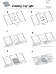
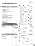
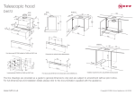
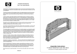
SKYROOM INSTALLATION MANUAL
RINGBEAM & BOX GUTTER ASSEMBLY
1
3
Check that frames are square by measuring
equal distances from corner to corner.
Lift the rear box gutter including the ringbeam and
place it on top of the side window frames.
2
4
Remove the ringbeam flaps from the ringbeam.
Centre the gutter on the frames.
7
9
Lift the final front ringbeam into position and slide
the ringbeam bracket into the channel on the
adjoining ringbeams and push together.
Fix the box gutter securely to the rear wall (see Figure 1).
8
10
Fix the ringbeam to the window frames
around the perimeter of the Skyroom roof.
Position the ringbeam flaps into place.
Flap engages at approximately 900.
SKYROOM REAR BOX GUTTER SECTION
5
Slide the ringbeam bracket into the
channel on the adjoining rear ringbeam.
6
Fix the ringbeam screws into
predrilled holes from above.
11
Lift the side gutters into place, by hooking them
onto the hanger plate fixed to the ringbeam.
FIGURE 1
2
3
A-FRAME PREPARATION & ASSEMBLY
12
14
16
4
Slide the side gutters over the angle corner brackets
fixed to the rear box gutter and fix with screws.
Tighten the joints by screwing an angled corner
bracket into the adjoining aluminium gutters.
Cover the inside of the aluminium box
gutters at the corners with sealant.
13
15
17
Fit the front gutter by hooking it
onto the pre-fixed hanger plate.
Screw the aluminium gutters and the
ringbeams together at approx 400mm centres.
Push the plastic moulded corners inside
the corners of the aluminium box gutters.
1
3
5
Layout the routed ridge, central
rafters and tie bars on the ground.
Engage the rafter bracket into
the slot provided on the ridge.
Screw into position by fixing the top screw.
2
4
6
On a hidden tie bar, push the steel bracket
into the routed side of the central rafters.
Slide the rafter over the bracket, making sure
it locates in the central bracket channel.
Slide the adjacent rafter over the steel angled bracket.
5
RAFTER ASSEMBLY
7
9
Place the rafter into the slot on
the ridge and slide the rafter up.
Fix remaining rafters on the main A-frame.
8
10
Screw into position by fixing the top screw.
Lift the main A-frame into position.
1
3
5
Slide the ridge end rafter
over the pre-fixed ridge bracket.
Fix the opposite ridge end rafter.
Secure the hip rafter by fixing the top screw.
2
4
6
Tighten the pre-fixed screw
to secure the ridge end rafter.
Slide the hip rafter over the bracket
and push it tight against the ridge.
Rotate the ringbeam flaps keeping them
tight against the hip rafter cut before fixing.
RIDGE ASSEMBLY
6
7
GLAZING
7
Before fixing down the rafters, temporarily fit
foam boards against flap to correctly space
rafter positions.
8
Fix each side of the hip glazing
seat into the ringbeam flaps.
1
Once rafters are fixed, remove the
foam boards and locate the glazing shelf.
2
Glue packers into place at bottom glass end closers.
FIGURE 2: SCREW POSITION
9
3
Once the rafters are in position pull the ringbeam
flap up tight to the rafter and fix centrally with
a screw (see Figure 2).
Slide glazing end closer over the bottom of the glazing.
4
Lift glass into place behind the rafter end
stops and press down glazing. Make sure
the protective yellow tape is removed.
IMPORTANT NOTE:
It is vital when box gutters are required
that adequate support is considered
in the way of brick piers or gallow
brackets. Always fix the gallow brackets
and packer before the roof is glazed.
8
5
Fit all the rear units of glass keeping the
glazing end closer between the rafters.
6
Position the plastic central pressure plate
over rear rafters and fix with screws.
9
INTERNAL RINGBEAM
1
Fix angle cleat to the side of the upper ringbeam.
PRESSURE PLATE & COVER CAP
2
Slide the upper ringbeams into
position between the rafters.
1
Glaze the remainder of the roof once
all the upper ringbeams are fitted.
2
Fit remaining pressure plates into position.
FIGURE 3: CLEAT POSITION
3
4
10
3
Screw through the angle brackets
into the side of the rafters.
Screw fix the upper ringbeams through the
pilot holes provided into the side of the hip rafter.
5
Fit the remainder of the upper ringbeams into position.
5
Centralise the ridge pressure plate
between the rafter pressure plates.
Position the ridge cover cap over the ridge
pressure plate and clip down securely.
Clip on the external cover caps.
4
6
Fix the ridge pressure plate centrally
to the main ridge body with screws.
Fit the gusset cover over the
hidden tie bar. Secure with screws.
11
CORNICE INSTALLATION
1
3
5
12
Lift the external cornice into position by positioning them
at the bottom edge of the aluminium gutter and let them
drop into place (see Figure 4).
Mark out the cornice 70mm
and 210mm from the bottom.
Use the cornice bracket again to drill the
top 210mm hole right through the cornice.
2
4
6
Fit remainder of cornices.
Firstly use the cornice bracket to mark the
70mm hole. Drill through the small pilot hole,
but only mark the aluminium cornice.
Screw the bottom mushroom screw through the
semi-drilled holes in the cornice. On the top hole
line through the smaller hole on the bracket
internally with the drill hole on the cornice.
7
9
11
Drill the top mushroom screw through the cornice
into the bracket held at the back of the cornice.
Slide the finishing corner cornice angle over the
mushroom screws by sliding them up from below.
Drill a circular hole in the aluminium
gutter to create the downpipe outlet.
8
10
12
Mushroom screws are tightened to hold corner square.
Stick on the arrow shaped flat trim to the underside
of the gutter to conceal the joint.
Fix the aluminium cornice support straps with screws
from the top of the aluminium rafter cover cap to the
back of the external cornice at each rafter.
Screw the outlet connector
provided into the hole and tighten.
13
INTERNAL PELMET
1
Centralise the vertical ladder frame onto the
horizontal bottom frame and fix together with
the screws provided.
FIGURE 4
2
Lift the longer ladder frame into
position between the ringbeams.
FIGURE 5
3
5
14
Fix the hinge attached to the ladder frame onto
the inside of the upper ringbeams. Make sure
ladder frames are level before securing.
Fix the remainder of the ladder frame making
sure the internal corners are securely fitted.
4
6
When frames are level fix the ladder frame
to the back of the ringbeam (see Figure 5).
Screw plasterboard into the steel ladder grids.
15