1
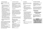
INSTALLATION MANUAL
Decoration panel
BYCQ140CW1
BYCQ140CW1W
1
2
3
5
c
b
a
e
5
4
1
2b
1
2
g
a
5
3
2
1
1
1
d
4
4+6
45°
f
4
h
5
g
5
g
b
b
2
5
3
6
4
2
4
1
3
2
6
3
3
1
4
6
7
8
1
2
2
3
4
7
9
5
8
6 7
6
7
9
5
6
≤12 mm
3
BYCQ140CW1
BYCQ140CW1W
Installation manual
Decoration panel
Preparing the decoration panel for installation
■
The BYCQ140CW1W has white insulations.
Be informed that formation of dirt on white insulations
is visibly stronger and that it is consequently not
advised to install the BYCQ140CW1W decoration
panel in environments exposed to concentrations of
dirt.
When using the BYCQ140CW1W decoration panel it
is advised to change the filter cleaning display
indications on the remote controller from light to
heavy. Changing the setting to heavy corresponds to
filter cleaning display indications in case of higher
contamination of the air. Refer to the indoor unit
installation manual under paragragh "setting air filter
sign" or "field setting", depending on the type of
indoor unit.
■
Read this manual attentively before installation. Do
not throw it away. Keep it in your files for future
reference.
Improper installation or attachment of equipment or
accessories could result in electric shock, shortcircuit, leaks, fire or other damage to the equipment.
Be sure only to use accessories made by Daikin
which are specifically designed for the use with the
equipment and have them installed by a professional.
If unsure of installation procedures or use, always
contact your dealer for advice and information.
1
Remove the suction grille from the decoration panel.
■ Push the suction grille lever (5) inward and open the grille (2).
(See figure 1)
1
Decoration panel
2
Suction grille
3
Corner decoration cover
4
Swing flaps
5
Lever
■ See figure 2. Detach the suction grille from the decoration
panel by lifting the grille up approximately 45 degrees (1)
until the position is reached on which removal of the grille is
possible (2).
■ Remove the transporting cardboard (3) from the decoration
panel (in 4 locations).
■ Remove the transporting tape (4) from the back of the
suction grille (5) (in 4 locations).
2
Remove the corner decoration cover on each corner by pulling it
up in the direction of the arrow. (See figure 3)
INSTALLATION
BEFORE
INSTALLATION
■
Leave the unit inside its packaging until you reach the
installation site.
■
Refer to the installation manual of the indoor unit for items not
described in this manual.
OF THE DECORATION PANEL TO
THE INDOOR UNIT
Refer to the installation manual of the indoor unit for details on
installing the indoor unit.
1
Install the decoration panel (See figure 5)
a
NOTE
To the installer
Be sure to instruct the customer how to properly
operate the system showing him or her the
operation manual of the indoor unit.
Accessories
Mounting bracket
b
Hook
c
Piping section
d
"Piping side" marking
e
Drain section
f
"Drain side" marking
g
Temporary latch
h
Swing flap motor lead wire
Installation manual
PREPARATION
1
Hold the decoration panel against the indoor unit by
matching the piping side and drain side marks on the
decoration panel with the position of the piping section and
drain section of the indoor unit.
2
Temporarily install the decoration panel to the indoor unit by
hanging the temporary latch into the hooks of the indoor unit
body. (2 locations)
3
Hook the 4 mounting brackets on the corner sections of the
decoration panel onto the hooks around the indoor unit body.
Make sure that the swing flap motor lead wire is not caught
between the indoor unit and the decoration panel.
4
Screw all 4 hexagon head screws located in the corner
section in for approximately 5 mm. The panel will rise.
5
Adjust the decoration panel by turning it in the direction
indicated by the arrows on the figure so that the ceiling
opening is completely covered.
6
See figure 6 (cross section of the air outlet) and tighten the
hexagon head screws until the thickness of the sealing
material between the decoration panel and the indoor unit
reduces to 12 mm or less.
BEFORE INSTALLATION
For this unit, you are able to select air flow directions. To discharge air
in 2 or 3 directions, it is necessary to purchase the optional blocking
pad kit for sealing air discharge outlets.
Handling of the decoration panel
To prevent any damage to the decoration panel, take care of the
following:
- Never place the panel facing down.
- Never let the panel lean against a wall.
- Never put it down on a projecting object.
- Never touch or put pressure on the swing flap in order to
prevent malfunction of the swing flap.
BYCQ140CW1 + BYCQ140CW1W
Decoration panel
4PW48467-1
Installation manual
1
INSTALLATION OF THE SUCTION GRILLE AND THE
1
Indoor unit
2
Ceiling
CORNER DECORATION COVER
3
Sealing material
4
Decoration panel
5
Swing flap
Install the suction grille by reversing the procedure shown in
paragraph "Preparing the decoration panel for installation" on page 1.
6
Air outlet
■
Install the suction grille
Precautions
■
Improper tightening of the screws (see figure 4) may cause air to
leak into the unit and between the ceiling and the decoration
panel (1) resulting in formation of contamination (2) and dew (3).
■
If there is a gap remaining between the ceiling and the
decoration panel after tightening the screws, re-adjust the indoor
unit body height (see figure 9). Adjustment of the indoor unit
body height is possible through the holes in the corners of the
decoration panel. The indoor unit must be kept levelled and the
drain piping kept unaffected.
2
Wiring of the decoration panel (See figure 8)
After hooking the suction grille to the decoration panel, attach
the strings of the suction grille to the pins of the decoration
panel.
NOTE
Make sure that strings are pushed down to the
footing of the pins, so that strings cannot shove off
the pins.
Make sure to turn off the power supply before wiring!
1
Swing flap motor lead wire (decoration panel side)
2
Connector
3
Swing flap motor lead wire (indoor unit side)
4
Swing flap motor lead wire
5
Electric components box lid
6
Hooks
7
Screw (2 locations)
■ Remove the electric components box lid.
Loosen the 2 screws, slide the electric components box lid in
the direction of the arrows and disengage it from the hooks.
■
It is possible to install the suction grille in 4 directions by simply
turning it 90 degrees.
■
Change the direction when adjusting the direction of the suction
grille of multiple units or to comply with demands of the
customer.
NOTE
■ Securely connect the connectors for swing flap motor lead
wire installed on the decoration panel.
■ Replace the electric components box lid reversing the
procedure to remove it.
Make sure that the swing flap motor lead wire is not
caught between the indoor unit and the decoration
panel and inbetween the electric component box lid.
Make sure that strings are not hanging out
inbetween the decoration panel and the suction
grille.
Install the corner decoration cover
(See figure 7)
1
Attach the string of each corner decoration cover to the pin of
the decoration panel.
NOTE
2
When the corner decoration cover gets loose
during maintenance of the decoration panel of the
indoor unit, the string prevents the corner
decoration cover from falling on the floor and
getting damaged.
Install each corner decoration cover.
■ First insert the hook at the square tip of the corner decoration
cover into the hole at the decoration panel corner.
■ Then position the 4 latches of the corner decoration cover to
fit into the holes of the decoration panel and gently push the
corner decoration cover onto the decoration panel.
Installation manual
2
BYCQ140CW1 + BYCQ140CW1W
Decoration panel
4PW48467-1
NOTES
4PW48467-1
Copyright © Daikin