1
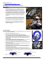
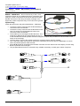
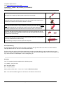
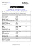
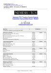
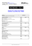
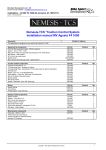
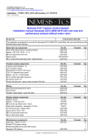
Competition Systems Ltd - UK
Tel 0044 (0)8707 444666 / Fax 0044 (0)8707 444888
E-mail: [email protected] www.competitionsystems.co.uk
Installation – 1098R – AA (revision_04, 31/08/2011)
Author – Mick Boasman
Nemesis-TCS ‘Traction Control System
Installation manual 1098R - Type – AA for race seat
Kit part No.
TCS-1098R.AA
Application - 1098R using the race type seat fairing. The TCM clamps to the rear sub frame cross member. For
1098R applications with a standard seat unit and DTC mount the TCS clamp will not be needed.
Speed pick up components
Front left speed bracket
Front left axle spacer
5 bolt trigger disk assembly
Speed sensor
M8 Washer - Aluminium
M6 x 16 Zinc Hex head cap screw - Speed sensor
Part No
Checked
CSD1327
CSD1281
CSP1014
23813030401
CSP1013
CSP1019
Qty
1
1
1
1
5
1
Traction module components
Traction Control Module
Bobbin - Dia 10x15, M5 x12mm
Bracket set race seat, inc 4 x cap screws
M5 Serrated Flange Nut
Part No
TCM
CSP1012
CSD1288
CSP1017
Checked
Qty
1
3
1
6
Wiring
Coil wiring
CAN and Inputs wiring
Front speed ext cable
Throttle signal - quick link (red)
Part No
CSW1285
CSW1299
CSW1411
CSP1015
Checked
Qty
1
1
1
1
Display module components
Display module
Spacer
M6x35 S/S cap head screw
Center bracket - TC-Pod
Push button assembly - blue/green TC-Pod
Double sided glue pad
M3x8 Hex button head
Part No
TC-Pod
CS1258
CSP1016
CS1243
CS972
CSP1020
CSP1018
Checked
Qty
1
1
1
1
1
2
2
Miscellaneous components
Cable ties - 200mm x 4mm
Printed TCS over view manual
Printed TCS 1098R AA manual
Nemesis-TCS stickers
Part No
CSP1021
Checked
Qty
16
1
1
6
CSP1022
Copyright – Competition Systems Ltd 2010
1
Competition Systems Ltd - UK
Tel 0044 (0)8707 444666 / Fax 0044 (0)8707 444888
E-mail: [email protected] www.competitionsystems.co.uk
Installation – 1098R – AA (revision_04, 31/08/2011)
Author – Mick Boasman
IMPORTANT – To be read by ALL installers and owners
Diagnostic light
The Nemesis TCS directly controls the ignition coils on your bike. If you have a standard, re-flashed or DP ECU on
your bike the internal diagnostics will think there is a problem with the coils and activate the diagnostic light on your
dashboard. There is no way to avoid this.
Terms of use
The presence of the Nemesis-TCS does not take away the responsibility of the rider to operate the bike correctly
within their own abilities, the track conditions and the laws of physics.
The system is designed to achieve greater on-track performance by the use of power modulation during wheel slip
events, but in no way should it be considered possible for the system to recover from every conceivable loss of grip.
The onus for safety always rests with the rider to stay within his or her own abilities, and to ensure that the ‘on-bike’
equipment is programmed, setup correctly, and an appropriate TC level selected for the skill of the rider, the bike
and the track conditions.
This equipment is intended for racing or track day performance use only and where exhaust emission controls are
not applicable.
By installing and using the Nemesis-TCS you automatically indemnify Competition Systems Ltd, our suppliers and
our authorised dealers from all first party or third party loss or damages. Normal components warranty is not affected
Battery
It is recommended that the standard battery be used with this system.
TC Module Mounting:
• Disconnect and remove the standard DTC module.
• Fit the 3 rubber bobbins inside the apertures in the TCS
module housing and secure with three of the M5 flange
nuts
• Fit the mounting bracket to the rubber bobbins and
secure to the rear frame as seen in this picture.
• When finished the carbon face of the TC module should
be on the underside and level with the floor when the
bike is resting on its wheels
• The wiring should be cable tied to the left and right subframe tubes
IMPORTANT – Certain aftermarket sub frames are smaller
diameter than standard, always ensure that the clamps are fully
tight to avoid the TC module coming loose. Do NOT rely on tape
to pack out the clamps, use metal shim or drill and tap the
brackets / frame
IMPORTANT – always check the clearance at the back of the TC
module to the angled frame tube, if less than 3-4mm clearance
exists, use
washers to pack
out the bobbins
Top View
and raise up the
carbon face is on underside
TC Module
Front of bike
TC Module
Check clearance here
Minimum 3-4mm
Sub frame
tube
IMPORTANT – If the Module is fitted in an incorrect orientation or
angle to the system will not work as it is designed.
Copyright – Competition Systems Ltd 2010
2
Competition Systems Ltd - UK
Tel 0044 (0)8707 444666 / Fax 0044 (0)8707 444888
E-mail: [email protected] www.competitionsystems.co.uk
Installation – 1098R – AA (revision_04, 31/08/2011)
Author – Mick Boasman
TC-Pod Fitting:
• Due to limited clearance on the handlebars the TC-Pod
should be fitted centrally just in front of the dashboard
using the angled bracket CS1243. This can be held in
place using the double sided adhesive or any alternative
method using the single mounting hole. The pod should
be pushed back as far as possible so that the upper edge
touches the front lower face of the dash, the kit contains
a small piece of foam tape to avoid wear on the dash
surround
•
Mount the CS972 switch assembly to the upper or lower
clutch master cylinder clamp using the longer bolt and
spacer provided. Connect the CS972 switch assembly to
the TC-Pod via the 4 way connector of the TC-Pod
•
Important note – The TC-Pod supplied, as part of the
TCS is not the same as the standard TC-Pod. Do not
attempt to swap parts
Front Wheel Speed:
Your TCS kit comes with a dedicated 10-tooth trigger disk, sensor, and axle spacer
for use on the left side of the bike.
•
•
•
•
•
•
•
•
•
Remove the front wheel from the bike
Remove the 5 bolts that secure the left brake disk in place
If your brake disks have small sunken rebates in their surface to
accommodate the bolt heads, these must be filled using the 5 aluminium
washers provided. Failure to do this will distort the trigger disk and more
importantly may cause the brake disk to come loose in service - See
images below
Fit the new blue trigger disk using the original bolts and secure using the
recommended thread lock agent and tightening torque
Ensure that the trigger disk is sitting flush against the brake disk
Re-fit the wheel, replacing the standard spacer with the new thinner spacer
and sensor mounting
The sensor gap is fixed and no adjustment is required by the user. The
design gap is between 1mm and 2.5mm
The sensor maximum range is over 4mm for smaller targets and 6mm for
larger targets, therefore no other ferrous objects should be installed
anywhere near this equipment
The sensor bracket can be fitted at any angle relative to the fork - this
makes no difference to the measurement. The image to the right shows the
sensor angled forwards to clear the wheel guard but it can be fitted in a vertical position if modification of the
guard is permissible.
Cap screw
Trigger tooth disk
use aluminium spacer in
these voids
Brake disk
Copyright – Competition Systems Ltd 2010
Cap screw
Trigger tooth disk
Brake disk
3
Competition Systems Ltd - UK
Tel 0044 (0)8707 444666 / Fax 0044 (0)8707 444888
E-mail: [email protected] www.competitionsystems.co.uk
Installation – 1098R – AA (revision_04, 31/08/2011)
Author – Mick Boasman
Quick shifter
The 1098R wiring is unique among Ducati in that there are 2 wires already in the standard loom located near the left
foot rest in a white connector, these are routed to the DTC module wiring and were presumably for a quick shift
option to DTC that was never realised.
Within the Nemesis-TCS we re-use these wires for exactly the same purpose.
Any ‘normally open’ switch can be used and will create a shift signal when these two wires are linked together.
WIRING – IMPORTANT – Do not connect any of the three TCS connectors directly to any standard bike loom
connectors (even if they fit). These 3 connectors must only be linked to the blue-banded connectors of the wiring we
supply. Damage to the equipment or bike components may occur if this rule is ignored.
Coil Wiring
Locate the wiring loom with yellow identification - CSW1285.
Connect the 6 way connector with the blue banding to
connector 1 of the TC Module.
Route the wiring along the left side of the bike following the
original wiring route.
Disconnect the loom wiring from the horizontal coil and use
the CSW1285 wiring loom to bridge the gap as shown below
and in the example image
Disconnect the loom wiring from the vertical coil and use the
CSW1285 wiring loom to bridge the gap as shown below.
Should it ever be necessary to isolate all TCS functions and
return the bike to normal operation, simply remove these links
and re-connect the coils back to their original loom
connections.
IMPORTANT – This wiring loom has a 6mm eyelet for direct
connection to battery negative. This must not be fastened to
any other ground location only battery negative.
1
2
3
1
2
3
1
2
1
Horizontal coil wiring from bike
2
3
3
Horizontal cylinder
Coil H
1
Coil V
1
2
3
1
2
3
1
2
Vertical coil wiring from bike
3
Vertical cylinder
1
2
3
Copyright – Competition Systems Ltd 2010
4
Competition Systems Ltd - UK
Tel 0044 (0)8707 444666 / Fax 0044 (0)8707 444888
E-mail: [email protected] www.competitionsystems.co.uk
Installation – 1098R – AA (revision_04, 31/08/2011)
Author – Mick Boasman
WIRING – IMPORTANT – Do not connect any of the 3 TCS
connectors directly to any standard bike loom connectors (even
if they fit). These 3 connectors must only be linked to the bluebanded connectors of the wiring we supply. Damage to the
equipment or bike components may occur if this rule is ignored.
Inputs wiring
Locate the wiring loom with yellow identification - CSW1299.
•
•
•
•
•
•
•
Connect the 8 way connector with the blue banding to
connector 2 of the TC Module.
Connect the 4 way connector with the blue band on the
new TCS wiring loom CSW1286 and connect it to
connector 3 of the TC Module.
The throttle input is the single wire D of this loom. This
needs to be attached to the orange signal wire (pin C)
of the standard bike throttle position connector using the red quick link provided in the kit, as shown in the
steps on the next page.
Connect wires F and G to the chassis connectors originally used for the DTC module
The 4 way black AMP connector E is used as the connection point for the WinTC USB adaptor so can be
left in any suitable position under the seat.
Wires B / A should be routed along the left side of the bike and are used to link to the display TC-Pod using
B and a pit limiter switch using A
The pit speed limiter A can be connected to any suitable momentary ‘normally open’ switch if required.
F
4
G
1
2
3
4
1
4
5
8
E
1
1
1
4
5
5
8
3
2
D
B
A
Copyright – Competition Systems Ltd 2010
5
Competition Systems Ltd - UK
Tel 0044 (0)8707 444666 / Fax 0044 (0)8707 444888
E-mail: [email protected] www.competitionsystems.co.uk
Installation – 1098R – AA (revision_04, 31/08/2011)
Author – Mick Boasman
Throttle quick link instructions.
The quick link is made up of three parts as seen here on the right:
Using the green section with the slot, push it over the orange throttle signal wire of
the bike loom until the wire rests at the bottom of the slot:
The large red centre section must be fitted the correct way around or the link will not
work. Locate the end with the sharp pointed tip protruding from the end of the outer
body and screw this end onto the green section until it rests firmly against the wire.
The sharp tip will pierce the outer sleeve but not sever the inner core of the wire:
Strip back the sleeve of the throttle input wire on the TCS loom CSW1278 so that
8mm of inner metal core is exposed. Push this into the red cap as seen here on the
right with inner core showing:
Screw this cap and wire into the main body ensuring that metal inner core and wire
cores are sandwiched and held securely.
Shrink sleeving can be put over this quick link if required.
Front speed wiring
The original front speed sensor wire connection is located on the right hand side of the frame. Use the extension
cable provided to link from this to the new front speed sensor.
For bikes which still use the original front speed sensor and pick up trigger disk, this can be retained but you must
inform you dealer notifying them of this so that a suitable map with the correct trigger teeth count can be installed. Or
if you have the Win-TC USB adaptor it can be changed by you.
PC Setup
Your TCS module should be loaded with the following maps:
111_1098R_1_Sxx_Rxx.S19
Sxx – Slip map version
Rxx – revision version
Status position offset value – 0.30 to 0.40 – Refer to WinTC View Data
Note : The WinTC installation guide can be found in the Nemesis-TCS manual.
Copyright – Competition Systems Ltd 2010
6