1
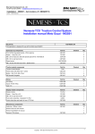
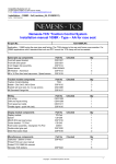
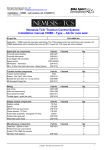
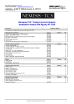
Competition Systems Ltd - UK
Tel 0044 (0)8707 444666 / Fax 0044 (0)8707 444888
E-mail: [email protected] www.competitionsystems.co.uk
Installation – MGS01 – AA (revision_01, 08/06/2011)
Author – Mick Boasman
Nemesis-TCS ‘Traction Control System
Installation manual Moto Guzzi - MGS01
UK
Tel – 08707 444 666
Fax – 08707 444 888
[email protected]
Kit part No.
TCS-MGS01.AA
This application is designed for use with the Moto Guzzi MGS01
Speed pick up components
Part No
Front left fork leg speed bracket - 25mm spacing
Checked
Qty
CSD1351
1
Spacer - 11mm Dia x 6.5
CS1258
2
M8 x 20 low head zinc disk bolts (Ducati spec) Pt No. 7070 083 20
CSP1034
6
M6 x 40 s/s cap head screw
CSP1025
2
23813030401
1
CSP1019
1
Speed sensor
M6 x 16 Zinc Hex head cap screw - Speed sensor
Traction module components
Part No
Traction Control Module
Checked
Qty
TCM
1
Frame clamp with 20mm dia + screws
CSD1316
1
Bobbin - Dia 10x15, M5 x12mm
CSP1012
3
M5 Serrated FlangeNut
CSP1017
6
Wiring
Part No
Checked
Qty
Coil wiring
CSW1356
1
Inputs / Power wiring
CSW1357
1
CAN / PC
CSW1358
1
Display module components
Part No
Display module
TC-Pod
1
Spacer - 11mm Dia x 6.5
CS1258
1
M6 x 40 s/s cap head screw
Push button assembly - blue/green TC-Pod
Double sided glue pad (apply to rear of TC-Pod)
Miscelaneous components
Qty
CSP1025
1
CS972
1
CSP1020
1
Part No
Cable ties - 200mm x 4mm
Checked
CSP1021
Checked
Qty
10
Printed TCS over view manual
1
Printed TCS MGS01 AA manual
1
Nemesis-TCS stickers
CSP1022
Copyright – Competition Systems Ltd 2011 – 10/3/2100
6
1
Competition Systems Ltd - UK
Tel 0044 (0)8707 444666 / Fax 0044 (0)8707 444888
E-mail: [email protected] www.competitionsystems.co.uk
Installation – MGS01 – AA (revision_01, 08/06/2011)
Author – Mick Boasman
IMPORTANT – To be read by ALL installers and owners
Terms of use
The presence of the Nemesis-TCS does not take away the responsibility of the rider to operate the bike correctly
within their own abilities, the track conditions and the laws of physics.
The system is designed to achieve greater on-track performance by the use of power modulation during wheel slip
events, but in no way should it be considered possible for the system to recover from every conceivable loss of grip.
The onus for safety always rests with the rider to stay within his or her own abilities, and to ensure that the ‘on-bike’
equipment is programmed, setup correctly, and an appropriate TC level selected for the skill of the rider, the bike
and the track conditions.
This equipment is intended for racing or track day performance use only and where exhaust emission controls are
not applicable.
By installing and using the Nemesis-TCS you automatically indemnify Competition Systems Ltd, our suppliers and
our authorised dealers from all first party or third party loss or damages. Normal components warranty is not affected
TC Module Mounting:
• Fit the 3 rubber bobbins inside the apertures in the TC module
housing and secure with three of the M5 flange nuts
• Fit the mounting bracket to the rubber bobbins and secure to
the rear frame cross member as seen in this image
• When finished the upper carbon face of the TC module should
be on the underside and level with the floor when the bike is
resting on its wheels. Module orientation should be as seen in
the diagram
• The wiring should be cable tied to the left and right sub- frame
tubes
• IMPORTANT – DYNO When running the bike on a dyno or
prolonged periods at low speed that produce limited airflow
under the seat it is recommended that the TCS module be
protected from heat damage. Warranty will not be given for
heat soak damage
Note – Ensure the module is free from contact of all other
components by at least 4mm
Copyright – Competition Systems Ltd 2011 – 10/3/2100
Top View
carbon face
Front of bike
2
Competition Systems Ltd - UK
Tel 0044 (0)8707 444666 / Fax 0044 (0)8707 444888
E-mail: [email protected] www.competitionsystems.co.uk
Installation – MGS01 – AA (revision_01, 08/06/2011)
Author – Mick Boasman
TC-Display pod Fitting:
• Mount the display pod to the aluminium area to the left of the
dashboard. It is recommended that a strong adhesive or Velcro
be used for this purpose.
•
Mount the CS972 switch assembly to the upper or lower clutch
master cylinder clamp using the longer bolt and spacer provided.
Connect the CS972 switch assembly to the TC-Pod via the 4 way
connector of the TC-Pod
•
Important note – The TC-Pod supplied, as part of the TCS is not
the same as the standard TC-Pod. Do not attempt to swap parts
Front Wheel Speed:
Your TCS kit comes with a dedicated bracket, sensor, spacers and different disc cap-head bolts.
•
•
•
•
•
•
•
Remove the 6 bolts that secure the right brake disk in place and replace with the 6 new low head cap bolts.
Fit to the manufacturer recommended torque and thread lock agent. Under no circumstances should any
alternative bolts be used.
Remove the two M6 spindle clamp bolts and push the Dia 11mm x 6.5mm spacers into the apertures. These
are designed to be a tight fit and it may be necessary to pull them into place using the bracket and new
longer screws we provide. This should be done carefully and evenly to avoid any damage to the threads or
bracket.
When installed correctly the assembly should look as seen
here.
Remove the rubber O ring from the sensor body and fit into the
rebate of the sensor bracket.
Apply a small amount of grease to the sensor body and push
the sensor into the bracket. Lock in place using one of the
M6x16 cap screws.
Ensure all screws are secure This is a safety critical
component and could result in wheel locking or TCS
failure if it were to come loose.
The sensor maximum range is approx 4mm for smaller targets
and 6mm for larger targets, therefore no other ferrous objects
should be installed anywhere near this sensor
IMPORTANT – Care should be taken when using paddock stands not to damage the wiring of the front speed
sensor.
Copyright – Competition Systems Ltd 2011 – 10/3/2100
3
Competition Systems Ltd - UK
Tel 0044 (0)8707 444666 / Fax 0044 (0)8707 444888
E-mail: [email protected] www.competitionsystems.co.uk
Installation – MGS01 – AA (revision_01, 08/06/2011)
Author – Mick Boasman
WIRING – IMPORTANT – Do not connect any of the three TCS
connectors directly to any standard bike loom connectors (even if they
fit). These 3 connectors must only be linked to the blue-banded
connectors of the wiring we supply. Damage to the equipment or bike
components may occur if this rule is ignored.
Coil Wiring
Locate the wiring loom with yellow identification - CSW1356.
Connect the 6 way connector with the blue banding to connector 1 of
the TC Module.
Route the wiring along the left side of the bike and follow the battery
positive cable up into the region of the coils.
Disconnect the loom wiring from the left coil and use the CSW1356
wiring loom to bridge the gap as shown below.
Disconnect the loom wiring from the right coil and use the CSW1356
wiring loom to bridge the gap as shown below.
The ground connection 2 should be fitted directly to the battery
negative.
IMPORTANT – Failure to fit the ground securely can lead to misfire /
engine not starting / TCS module damage. This is the main power
ground for the coil system.
Should it ever be necessary to isolate all TCS functions and return the
bike to normal operation, simply remove these links and re-connect the
coils back to their original loom connections.
Right coil
Right coil wiring from bike
Coil R
1
battery ground
2
Left coil
left coil wiring from bike
Coil L
Copyright – Competition Systems Ltd 2011 – 10/3/2100
4
Competition Systems Ltd - UK
Tel 0044 (0)8707 444666 / Fax 0044 (0)8707 444888
E-mail: [email protected] www.competitionsystems.co.uk
Installation – MGS01 – AA (revision_01, 08/06/2011)
Author – Mick Boasman
WIRING – IMPORTANT – Do not connect any of the 3 TCS connectors directly to any standard bike loom
connectors (even if they fit). These 3 connectors must only be linked to the blue-banded connectors of the wiring we
supply. Damage to the equipment or bike components may occur if this rule is ignored.
Inputs wiring
Locate the wiring loom with yellow identification - CSW1357.
Connect the 8 way connector with the blue banding to
connector 2 of the TC Module.
Route the wiring along the right side of the sub frame all the
way to the ECU body. At this point branch off the connectors A
and B towards the throttle sensor.
Throttle – Disconnect the 3 way connector from the throttle
sensor and bridge the gap using connectors A and B. Note that
the clearance behind the sensor connector is quite tight and it
will be necessary to bend over the flexible cover of the wiring.
Now route the remaining wiring under the back of the ECU to
the left side of the bike and follow the route of the standard bike
wiring towards the front.
Rear speed – Disconnect the 3 way white plastic connector of the rear speed sensor. This is located just above the
throttle cables. Bridge the gap using connectors C and D. Note that this connection provides switched power and
sensor grounding as well as the rear speed signal to the TCS system. It is recommended that this connector be
protected from water ingress and checked regularly for corrosion.
Front speed - Route the front speed wiring along the left side of the bike following the original wiring route. Use the
left brake line as a guide for the cable run and connect to the front speed sensor. This sensor is fundamental for
system operation and care must be taken to avoid chaffing or damage during use.
3
2
1
1
A 23
B
1
1
2
3
C
E
1
2
5
2
3
150
1
2
3
D
Copyright – Competition Systems Ltd 2011 – 10/3/2100
3
2
1
5
Competition Systems Ltd - UK
Tel 0044 (0)8707 444666 / Fax 0044 (0)8707 444888
E-mail: [email protected] www.competitionsystems.co.uk
Installation – MGS01 – AA (revision_01, 08/06/2011)
Author – Mick Boasman
WIRING – IMPORTANT – Do not connect any of the 3 TCS
connectors directly to any standard bike loom connectors (even if
they fit). These 3 connectors must only be linked to the bluebanded connectors of the wiring we supply. Damage to the
equipment or bike components may occur if this rule is ignored.
CAN and PC Wiring
Locate the wiring loom with identification - CSW1358.
Locate the 4 way connector with the blue band on the new TCS
wiring loom CSW1358 and connect it to connector 3 of the TC
Module.
Route the wiring along the right side of the sub frame all the way
to the ECU body. Now route the wiring under the back of the
ECU to the left side of the bike and follow the route of the
standard bike wiring towards the front.
You can now plug the 4 way connector 3 in the drawing below into this 4 way connector.
PC - The 4 way black AMP connector F is used as the connection point for the WinTC USB adaptor so can be left in
any suitable position near the dashboard.
Display - Route the wiring to the left of the headstock tube and connect the 8 way ‘H’ connector to the TC-Pod
display.
Pit limiter - Connect the Pit limiter at connector G to a suitable momentary ‘normally open’ switch if required, or use
Part No. CSP1041 which plugs directly in.
1
4
5
8
4
H
G
1
1
F 23
4
PC Setup
Your TCS module should be loaded with the following maps:
120_MGS01_1_Sxx_Rxx.S19
Sxx – Slip map version
Rxx – revision version
Status Position offset value – 0.3 to 0.40 – Refer to WinTC View Data
Note : The WinTC installation guide can be found in the Nemesis-TCS manual.
Copyright – Competition Systems Ltd 2011 – 10/3/2100
6
3