Transcript
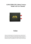
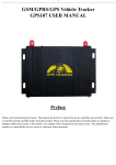
ECU installation
Sensor installation
Display
Red
White
Pink
Red
Reversing
light
Footbrake
ACC ON
Battery
Pink
Black
Brown
up
Brown
Equal
1. The positions of the
holes should be vertical
and even.
2. Measure & position
the sensors' locations.
3. Verify that the size of the
hole saw is compatible with
the diameter of the sensor.
5. Push the sensor into the
hole firmly with sensor pad
supplied with the product.
Installation Manual
Horn
GND
Right turn
signals
Left turn
signals
4. Install the sensor vertically,
the "up" sign must be on
upside.
6. Insert the plug into the socket
and wind the turncap tightly.
Sensor
Unpacking checklist
Display
Sensor
Display
ECU
Hole saw
ECU
Mount ECU at a concealed place in the driving
compartment and away from the switchboard.
Sensor pad
Sensor x 8
Sensor wire×8
Signal detection wire
User's Manual
Installation Manual
Wire harness×2
1. This unit is for vehicles with 12V DC only.
2. Unit should be installed by a professional auto technician.
3. Route wiring harness away from heat sources and electrical
components.
4. Power loom connections should be soldered and insulated.
5. Perform test after finishing the installation.
E-mail: [email protected]
Function Testing
Hold a wooden board
(30×100cm) standing in front of
the car, drive slowly to test the
corresponding functions of the
system according to user’s
manual.
Hold a wooden board
(30×100cm) standing at the
back of the car, reverse slowly
to test the corresponding
functions of the system
according to user’s manual.
Display installation
1. There are 5 recommended
locations you can install the
display, such as places on the
dashboard, the front windshield
or the A/C vent.
2. Remove the sticker
from the pedestal, the
display can be stuck
on the dashboard or
windshield firmly.
3. The display can be
fixed in the A/C vent
with the clip provided.