1
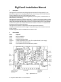
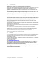
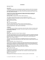
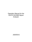
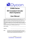
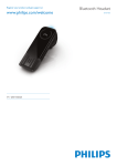
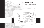
 Installation Manual
for D1110
DigiCom2
Dycon Ltd
Tel: +44 (0)1443 471 060
Fax: +44 (0)1443 479 374
Cwm Cynon Business Park – Mountain Ash – CF45 4ER - UK
www.dyconsecurity.com
[email protected]
TABLE OF CONTENTS
Section
Index
1
2
Description
Part numbers
3
3
3
4
5
6
What to do:
Installation
System testing
Troubleshooting
Helpdesk
4
4
5
5
The details:
Inputs and self learning
System power supply and battery
NVM programming, line monitoring
Calling
Select services
Inputs 1 – 8
Automatic test calls
PSTN line monitor
Output
6
6
7
7
7
7
7
7
8
Appendix 1 – LED indications
Appendix 2 – Input connections
Appendix 3 – Specification
Appendix 4 – Approvals
Appendix 5 – Glossary of terms
9
10
13
14
15
7
8
9
9.1
9.2
9.3
9.4
9.5
9.6
D1110 DigiCom2 Installation Manual - D1110-INST-EN/10F/v1
Page
-2
DigiCom2 Installation Manual
1.
Description
The DigiCom2 is an advanced auto-dialing digital communicator for alarm reporting. It can
transmit alarm signals to an Alarm Receiving Centre via the analogue PSTN (Public Switched
Telephone Network) using the ‘DTMF Fast Format’ protocol.
The DigiCom2 has 8 alarm inputs. When triggered by the alarm system, it initiates calls to the
Alarm Receiving Centre (ARC).
The DigiCom2 monitors the PSTN line continuously. If a fault occurs local annunciation is made.
The DigiCom2 comes complete with the “Alarm Abort” feature to enable older alarm systems to
comply with the ACPO false alarm policy (in the UK). Once the system is set, if a mis-operation
occurs and the system is unset within 90 seconds, a “Restore on Channel 3” or separate code
will be sent to the Alarm Receiving Centre.
The DigiCom2 is housed in an ABS plastic case which protects the electronics.
A tamper protected steel box with an integral 1 amp power supply is also available. See below
for part numbers.
An NVM Programmer D1154 is available that connects to a PC.
2.
Part numbers
D1110
D1055
D0354
D1154
D1520-B
D0730
D0402
DigiCom2
Box of 10 NVM ICs
NVM programmer
NVM programmer software
Tamper protected box with 1 amp, En-compliant Grade 2 power supply
Security ADSL (broadband) filter
Dycon products CD with manuals for all products
Fig. 1 – DigiCom2 D1110
D1110 DigiCom2 Installation Manual - D1110-INST-EN/10F/v1
-3
3.
Installation
Program the NVM for the system specific requirements, or obtain a programmed NVM from your
Alarm Receiving Centre. See page 15.
1.
2.
3.
4.
5.
6.
7.
Totally power down the control panel mains and battery.
Fit the (programmed) NVM into the 8-pin socket located at the front of the DigiCom2
module ensuring correct orientation. See Fig 1. The NVM should be programmed with
the D1154 NVM programmer.
Connect the input triggers as required. See Fig 1 and ‘Self Learning Inputs’ on page 6.
Connect the PSTN line to the terminals A and B. See pages 7 to 14.
Connect the 12 volt supply to the ‘12v +’ & ‘12v -’ terminals. See Fig 1 and page 14.
Reconnect the mains supply to the control panel.
Your DigiCom2 is now ready for testing.
4.
System Testing
Ensure you have informed your Alarm Receiving Centre that you are ready to test your
DigiCom product.
Note: If the NVM is faulty, fitted incorrectly or has been incorrectly programmed, the red and
yellow LEDs will flash alternately. If there is a problem with the PSTN telephone line, the red LED
will flash. See Appendix 1.
1.
2.
3.
4.
5.
6.
7.
8.
Power up the DigiCom2 - the unit will initialise.
Start testing by momentarily shorting the test pins on the DigiCom2. This will cause the
DigiCom2 to send a test signal to the Alarm Receiving Centre.
Once the test pins are shorted, the “Active” LED will illuminate. During communication
the LED will flash to indicate the progress of the call, see Appendix 1. When the
DigiCom2 successfully communicates with the Alarm Receiving Centre, the “Active” LED
will go off, this will mean that the test call is complete.
Now trigger all the used inputs on the DigiCom2. This should be done by setting the
control panel and triggering an alarm condition. If PA or fire circuits are being monitored,
these should also be triggered.
Contact your Alarm Receiving Centre to confirm that all signals have been received.
Ensure that all ‘Restore’ signals are received when the DigiCom2 input terminals return
to their quiescent value.
If the quiescent (non-active) states of the input terminals are incorrect, i.e. “positive
applied/removed” is inverted, then the ARC will report that the alarm/restore or
open/close is the ‘wrong way round. To correct this, use the self learning input feature.
See page 6.
If at any time you wish to cancel a call, short the reset pins. See Fig. 1.
If you are using the “Alarm Abort” feature, set the alarm panel, initiate an alarm condition
and (if the alarm system incorporates bell delay this will be overridden), unset the system
within 90 seconds. Check that the alarm abort signal has been sent to the Alarm
Receiving Centre and, if selected the alarm system has reset.
Your DigiCom2 is now fully tested.
D1110 DigiCom2 Installation Manual - D1110-INST-EN/10F/v1
-4
5.
Troubleshooting
Q. What if there appears to be random triggering of the DigiCom2?
Ensure that 0 volts is common across all parts of the alarm system. If the DigiCom2 receives its
power from a power supply that is additional to the alarm system, ensure that the 0 volt
connection on the additional power supply is connected to the 0 volt connection on the alarm
system.
Check that the supply voltage is sufficient for reliable operation. A supply voltage below 9v will
damage the standby battery and may generate spurious signals.
Q. What if the digital communicator is not received by the Alarm Receiving Centre?
Check that the NVM is fitted and has been correctly programmed, i.e. correct telephone
numbers.
Check that the PSTN line is properly connected. Check with a meter that approximately 48 volts
DC is present across the PSTN terminals marked A and B. Connect a telephone to the PSTN
line and make a call to ensure that it is fully functional. Remove telephone after test.
Disconnect any other equipment that is using the same PSTN line to ensure that it is not
inhibiting the DigiCom2.
Check that when the digital communicator is triggered, the voltage across the A and B terminals
drops to between 6 and 12 volts DC.
Ensure that ‘call barring’ to the ARC Receiver telephone number has not been set on the PSTN
line used by Digicom.
See Appendix 1 for line monitoring indications. These will help diagnose line problems.
Q. What if some channels are not received correctly by the Alarm Receiving Centre?
Check that the NVM has been correctly programmed for your requirements.
Repeat the ‘Learning the Inputs’ programming stage.
6.
Help Desk
If you have installed the DigiCom2 in accordance with these instructions, checked all the above
points but are still experiencing problems you can contact your DigiCom2 supplier or your
Telecom Service Provider.
In the UK, DigiCom2 installation, programming, operation or other questions may be addressed
to: Dycon Technical Support:
Tel: +44 (0)1443 471 064
Email: [email protected]
The Dycon web site: www.dyconsecurity.com contains the latest copies of all manuals for all
Dycon products. Please ensure that you are working from the latest version. You can also
download associated information and software samplers.
Sales, shipping and contact information is here too. A CD is available that contains manuals for
all Dycon products and the programming software for DigiCom and Dualcom. Contact our
Technical Support for more information.
D1110 DigiCom2 Installation Manual - D1110-INST-EN/10F/v1
-5
7.
Inputs and Self Learning
For full Inputs connection information see Appendix 2.
To aid installation, the DigiCom2 can learn the quiescent state of its inputs, i.e. the ‘not active’
state, without having to re-program the NVM.
This allows the unit to be programmed during installation with ‘positive applied’ or ‘positive
removed’ inputs. It will correct NVMs that have been supplied with incorrect input polarities.
1.
2.
3.
4.
5.
Setup the inputs ‘non-active’ conditions by connecting a positive voltage or ‘no’ voltage
(0v) on each input terminal as required. This is easily achieved by connecting the control
panel outputs to the DigiCom2 inputs, then put the control panel in the day state with no
activated detectors and all alarm conditions reset. You can leave any unused
DigiCom2 inputs disconnected.
‘Non-active’ means that the voltage on the alarm inputs are in the ‘not in alarm” condition
and open/close inputs are in the ‘open’, ‘unset’ or ‘day’ condition.
Ensure that the unset/open/day state is selected on the control panel, not the ‘set’ or
‘engineering’ states.
With the DigiCom2 powered up, apply a permanent short to the test pins with a jumper
link or screwdriver blade etc…
Momentarily short the reset pins.
The red and yellow LEDs will flash: 3 red... 3 yellow... 3 red... etc… indicating ‘learning’
mode.
Remove the short on the test pins.
The LED flashing will cease and the state of the 8 inputs will be remembered as the ‘nonactive’ condition. This information will be stored in the NVM.
When complete, DO NOT park the jumper link onto BOTH test pins because this will
immediately trigger a test call and inhibit further operation.
8.
System Power Supply and Battery
The DigiCom2 requires a supply of 12-13.8 volts DC at 6mA in standby and 20mA when
activated. The installer must ensure that the alarm system power supply is rated to provide
adequate power for this apparatus and for any other auxiliary apparatus drawing power from the
alarm system power supply.
If the supply voltage falls to below 11v, a “Low Voltage” signal will be transmitted to the ARC.
If the standby battery voltage falls below 9v (deep discharge), the battery may sustain permanent
damage. The DigiCom2 will, however, remain operational, but the red Fault LED will be
permanently on.
If the DigiCom2 receives its power from a power supply that is additional to the alarm system,
ensure that the 0 volt connection on the additional power supply is connected to the 0 volt
connection on the alarm system.
Only power supplies conforming to EN60950, EN41003 or International Safety Standards should
be used with this apparatus.
D1110 DigiCom2 Installation Manual - D1110-INST-EN/10F/v1
-6
9.
NVM Programming
The operating parameters for the DigiCom2, e.g. telephone numbers, are stored in the NVM
(Non Volatile Memory). The DigiCom2 is designed to use an NVM that has been specifically
programmed for it, or an NVM that has been programmed for a Scantronic 8400, 8440 or 9056
Digital Communicator.
Note: when using a Scantronic NVM, the option to specify regular dial-tone tests or the ACPO
Abort features will not be available. The NVM can be programmed using the D1154 NVM
programmer connected to a PC. The NVM can also be programmed by a Scantronic-type 7200
or 7300 programmer. Your Alarm Receiving Centre will normally provide a programming service
and will supply programmed NVMs on request. Professional installers may also have the D1154
and be able to provide a DigiCom2 programming service.
For a full list of programmable features see instructions for the D1154 NVM programmer.
9.1
Calling
a) DTMF Dialing
b) Three Way Calling (Select Services)
c) Three or four telephone numbers for PSTN alarm reporting.
9.2
Select Services
If the PSTN line for the DigiCom2 is not ‘outgoing calls only’, we recommend that your Telecom
Service Provider’s “Three Way Calling“ service (if available) is enabled on the phone line. The
NVM will need to be programmed with “3-way calling” enabled.
This will ensure that the DigiCom2 can make an outgoing PSTN call if the line is engaged by an
incoming call. See page 10 for recommended connections for security applications.
9.3
Inputs 1 - 8
There are 8 inputs on the DigiCom2. These inputs require 0 volts or a DC positive voltage (+4v to
+15v) to operate. They may be programmed to send an alarm call when a positive voltage is
applied to an input or when a positive voltage is removed, i.e. the input voltage is changed to 0
volts.
To assist triggering, there is one output terminal labelled ‘Stt +’ that supplies +12 volts via a
resistor. See Appendix 2.
9.4
Automatic Test Calls
Periodic test calls can be sent at intervals of 1 to 99 hours since the last call was made.
9.5
PSTN Line Monitoring
Any or all of the following PSTN tests may be switched on. If a problem is detected, the
DigiCom2 can operate the Aux relay:
a) 24 Hour DC Voltage
b) 24 Hour Off Hook Detect
c) 24 Hour Ringing Detect
d) Regular Dial Tone Detect
D1110 DigiCom2 Installation Manual - D1110-INST-EN/10F/v1
-7
9.6
Output
One output is provided. The connections marked Aux can be programmed to operate:
a) When a line fault is detected
b) If a communication attempt fails
c) If a communication attempt is successful
d) When a communication attempt is in progress
The Aux output may also be programmed to be normally on or normally off. In addition, the
output can be inverted by shorting the INV pins on the DigiCom2. The Aux output may be
programmed to be timed or latched. If latched, the Aux relay will remain in its active state until
the DigiCom2 is reset or power is removed and restored.
D1110 DigiCom2 Installation Manual - D1110-INST-EN/10F/v1
-8
APPENDIX 1
LED Indications
The LEDs are red and yellow, and labelled as ‘Fault’ and ‘Active’. See Fig 1.
Input Learning Indication
When the DigiCom2 is ‘learning’ the quiescent (non-active) state of its inputs, the red and yellow
LEDs will flash: 3 red... 3 yellow... 3 red... etc…
NVM Fault Indications
LEDS alternate flash - slow
(red, yellow, red, yellow ...)
NVM is faulty or fitted incorrectly
LEDS alternate flash – fast
(red, yellow, red, yellow ...)
(on and off 5 times per sec)
NVM is the correct type and is working,
but has been incorrectly programmed
Communication indications
The yellow “Active” LED will flash to indicate the progress of the call.
LED Off
PSTN path not activated
LED On solid
PSTN activated
LED Slow flash
Dialing or waiting for ‘handshake’ from receiving
equipment
LED Rapid flash
Handshake received, sending data to receiving equipment
LED 6 slow flashes
Communications successful. Data received correctly
at receiving equipment
Both ON
D1110 is resetting
PSTN Line Failure Indications
The Fault LED will flash to indicate the type of line or communication failure. If more than one
type of failure is detected, the lowest number will be displayed.
1 flash
PSTN telephone line DC voltage is very low or absent
2 flashes
Another telephone (or fax, modem etc…) on the same PSTN line is off-hook and
can inhibit the DigiCom2 from making a telephone call
3 flashes
Incoming ringing is detected and this will inhibit the DigiCom2 from making a
telephone call
On
Supply voltage to DigiCom is very low
D1110 DigiCom2 Installation Manual - D1110-INST-EN/10F/v1
-9
APPENDIX 2
Input Connections
There are 8 input terminals on the DigiCom2.
When the DigiCom2 is triggered, the voltages on the input terminals are 0 volts changing to a
positive voltage (+4 volts to +12 volts), or they may be a positive voltage changing to 0 volts. This
is called ‘positive applied’ or ‘positive removed’ triggering. All voltages are measured with
respect to 0 volts.
The inputs may be programmed to send an alarm call when a positive voltage is applied to an
input or when a positive voltage is removed. See the D1154 NVM Programming Manual for
details.
Note: Triggering voltages in excess of +16 volts may cause spurious operation. The DigiCom2
can ‘self learn’ its inputs and correct the NVM. See page 6.
ST+ Fig. 11
The diagram above shows the internal connections of the DigiCom2.
The +12 volt and 0v supply connections from the control panel or power supply is connected to
the +12v and - 12v terminals.
Each of the input terminals on the DigiCom2 is connected to 0 volts by a resistor. Therefore, by
leaving an input terminal unconnected will ensure that that input is connected to 0 volts and is
unused.
The ‘Start+’ (ST+) terminal on the DigiCom2 is an output. It will give a positive ’pull-up’ voltage
which can be used to assist input triggering. See page 11.
D1110 DigiCom2 Installation Manual - D1110-INST-EN/10F/v1
- 10
APPENDIX 2
Input Connections (cont’d)
D1110 DigiCom2 Installation Manual - D1110-INST-EN/10F/v1
- 11
APPENDIX 2
Input Connections (cont’d)
D1110 DigiCom2 Installation Manual - D1110-INST-EN/10F/v1
- 12
APPENDIX 3
Specification
Model
D1110 Stand Alone
Dimensions (h x w x d)
19 x 61 x 91 mm
Weight
80 grams
Telephone Path
Standard PSTN technology
Abort Facility
Built-in
Power Requirement
Max 13.8v Min 9.0v DC, 0.1volt max ripple
Current Consumption
6mA quiescent, 20mA operating
Low Battery
10.9-11.1 volts falling, 11.9-12.1v recovery
Outputs
1 Aux relay (24v 1A contacts)
Start Inputs
Max +15 volt, Min +3.5 volts DC
Temperature
-20°C to +60°C transit, -4°C to +5°0C operating
Humidity
0 - 80% non-condensing
Mounting
Any orientation
Warranty
2 years
D1110 DigiCom2 Installation Manual - D1110-INST-EN/10F/v1
- 13
APPENDIX 4
European PSTN Approval
The D1110 range of DigiCom2 products meets the requirements of the EU PSTN standard
CTR21 and is approved for connection to any exchange line forming part of a Public Switched
Telephone Network (PSTN).
AHCTR210 001
Declaration of Network Compatibility
The equipment has been approved in accordance with Council Decision 98/ /
EC ( 5 ) for pan-European single terminal connection to the Public Switched Telephone Network
(PSTN). However, due to differences between the individual
PSTNs provided in different countries, the approval does not, of itself, give an unconditional
assurance of successful operation on every PSTN network termination point.
In the event of problems, you should contact your equipment supplier in the first instance.
AHCTR211 001
Statement to Notified Body, Vendor and User
The equipment has been approved in accordance with Council Decision 98/ /
EC ( 5 ) for pan-European single terminal connection to the Public Switched Telephone Network
(PSTN).
The equipment has been designed for use in all 17 EU countries, plus Switzerland, but may have
interworking difficulties in Germany and Greece.
For use in Portugal it is necessary to ensure that a programming master chip, catalogue number
D1145-02 is used to ensure reliable operation with the Portuguese telephone network.
Approval Authority:
CE0168
D1110 DigiCom2 Installation Manual - D1110-INST-EN/10F/v1
- 14
APPENDIX 5
Glossary of Terms
Alarm Abort
A facility to reduce false alarms requiring police response. Specified by ACPO (The Association
of Chief Police Officers) in the UK. An “Alarm Abort” situation occurs when the alarm system is
set, and an alarm occurs, and it is then reset by the alarm system being unset by a key or valid
user code, all within 90 seconds.
This false alarm is often caused by the user of an alarm system failing to set the system
correctly. The “Alarm Abort” signal identifies this situation to the ARC thus avoiding an
unnecessary police visit to the site.
Analogue PSTN - Analogue Public Switched Telephone Network.
The analogue national telephone system, often just called the PSTN. Service
is available to customers on twisted-pair wires that carries a DC supply provided from the
network telephone exchange.
ARC - Alarm Receiving Centre
See ARS.
ARS - Alarm Receiving Station
A 24-hour manned centre (often privately owned and operated) capable of
receiving and logging calls of alarm, and forwarding them to security authorities
and other relevant services. Often called a Central Station.
Call Minder
A call answering service offered by some telecom Service Providers. When an incomming call to
the subscriber’s telephone is not answered, the Service Provider can record it and forward it to
the subscriber at a later time.
Central Station
See ARS.
Digital PSTN - Digital Public Switched Telephone Network.
The digital national telephone system. Service is available to customers on twisted-pair wires that
carry a DC supply provided from the network telephone exchange, on optical fibre or other digital
transmission medium. The digital service may be in ISDN format or another digital format.
DTMF - Dual Tone Multi Frequency
The series of tones used by telephones to send dialling information to an analogue PSTN
exchange. These tones are also used by the DTMF Fast Format and Contact ID alarms reporting
protocols.
DTMF Fast Format - Alarms Reporting Protocol
A protocol that is a sequence of analogue tones (push-button telephone tones) used to send via
telephone lines a transmission to receiving equipment at an ARC, and to receive checking and
acknowledgement replies from that receiving equipment. Eight or 16-channel DTMF Fast Format
protocol is commonly used in burglar or intruder alarm equipment.
EEPROM - Electrically Erasable Programmable Read Only Memory.
A type of NVM. See NVM.
NTP - Network Termination Point
A telephone line is terminated at the users premises by a Network Termination Point which is
provided by the Telecomms Service Provider. This is a socket or connection where the users
equipment can be connected.
NVM - Non Volatile Memory.
An integrated circuit memory device that does not need any power to remember data.
D1110 DigiCom2 Installation Manual - D1110-INST-EN/10F/v1
- 15
APPENDIX 5
Glossary of Terms (cont’d)
PABX - Private Automatic Branch Exchange
A small telephone exchange for use within one building or group of buildings. Commonly used in
businesses where each phone in that business is an extension on that PABX. Usually connects
to one or more analogue PSTN or ISDN telephone lines.
PSTN - Public Switched Telephone Network.
A national telephone system. This may be analogue and/or digital. See analogue PSTN.
Terminal Adapter
A device that connects to the S-bus connection of an ISDN Network Termination
Point and adapts the digital S-bus data, i.e. protocol, data speed, structure, to that required, e.g.
the conversion may be to analogue PSTN or to a serial port for cable connection to a PC’s serial
‘COM’ port.
3-Way-Calling
This is a service provided by some telecommunication service providers. BT in the UK offers this
service. When a call is in progress on a telephone line it is possible to send a signal via that line
to the equipment at the telephone exchange. The exchange will put the current call on ‘hold’ and
provide a dialing tone so that another outgoing call may be made. When this second call has
finished a signal to the exchange will disconnect the second call and re-connect the first one that
was put on ‘hold’.
D1110 DigiCom2 Installation Manual - D1110-INST-EN/10F/v1
- 16