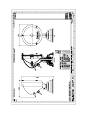
1
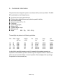
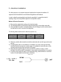
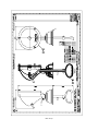
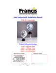
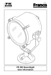
User Instruction & Installation Manual M9 & M10 Searchlight Product Reference Number: A2059 – M9 Silver Finish A2060 – M9 White Finish A2084 – M10 Silver Finish A2085 – M10 White Finish Manufacturer’s details: Distributor details: Francis Searchlights Ltd Union Road, Bolton Lancashire, BL2 2HJ, UK Tel: +44 (0) 1204 558960 Fax: +44 (0) 1204 558979 http://www.francis.co.uk E-mail: [email protected] Manual Part Number: C24187 Issue: 1 CONTENTS 1 - Introduction 2 - Safety Precautions 3 - Technical Information 4 - Unpacking and Installation Instructions 5 - Electrical Installation 6 - Operating Instructions 7 - Fault Finding 8 - Maintenance and Servicing 9 - General Assembly Drawing 10 - Spare Parts List 1 - Introduction It is imperative that this manual is read carefully and understood before installing your equipment. For your future reference please keep this manual in a safe place. Thank you for specifying a product from the Francis Searchlights range. All Francis products are designed to give complete customer satisfaction and are manufactured to the highest engineering standards in order to ensure optimum performance and service life. The Francis Halogen ranges combine features proven over many years’ service in the most hazardous conditions in both marine and land installations. In order to prolong the life and performance of your product, we recommend that you only specify Francis Searchlights spare parts. This will also ensure that any warranties on your equipment will not be invalidated. Information on spares ordering and parts is provided in this manual. Should you ever need to contact Francis Searchlights Ltd. regarding your equipment, please quote the Product Serial Number at all times. Back To Top 2 - Safety Precautions The following instructions must be adhered to, in order to ensure a safe working environment and the safety of the user. Prevent rain, snow, condensation and water droplets from contacting the lamp as this may cause bulb failure, and possible shattering; Quartz halogen lamps run with a high internal pressure in excess of atmospheric. Whilst the construction is inherently strong, there is a slight risk of the lamp shattering; Never look directly into an illuminated searchlight as this may cause severe damage to eyesight. If it is necessary to inspect a lamp whilst in operation, always wear suitable protective goggles; Should it be necessary to examine the lamp with the front bezel removed, always use a protective shield to ensure a safe working environment; Never attempt to clean the lamp when in use; Searchlights get hot. Never touch the unit when lit and always allow at least ten minutes for cooling down after turning off; Ensure the lamp has cooled sufficiently before removal. During the cooling down period avoid mechanical or thermal shock to the lamp as this may cause shattering; If undue force appears necessary to remove the lamp, the equipment should be inspected by a competent person, or contact the manufacturer; When breaking a lamp for disposal, care must be taken to ensure that the fragments are safely contained. Precautions must be taken against flying glass and other fragments. This operation should be performed outdoors or in a well-ventilated area. In ALL cases reference should be made to the lamp manufacturers instructions packed with the lamp; Due to the vast range of lamps available, it may appear possible that more powerful lamps can be used in the equipment for which it was designed. Even when the unit will physically accept a higher wattage lamp, this substitution is not recommended as it could be dangerous; Back To Top 3 – Technical Information This product has been designed to operate in accordance with the product specification. The M9 & M10 searchlights have the following features: Constructed from marine grade aluminium; Polished, electro-brightened super purity aluminium parabolic reflector; Stove enamel painted; Vertical movement +35° to -35°; Fixed focus; Toughened front glass; Sealing to IP65; Tungsten Halogen Lamps; Solas approved; Weight M9 – 1.7Kg M10 – 2.2 Kg The searchlight also performs to the following optical data: Volts Watts Range @ 1 Lux P.B.C.P. x 1000 Div. Lamp Life Lamp Cap Part Number 12v 12v 12v 12v 24v 50 50 100 100 100 164 332 409 242 191 3.4 3.0 4.0 4.6 4.7 3000 Hrs 50 Hrs 50 Hrs 2000 Hrs 2000 Hrs G6.35 G6.35 G6.35 G6.35 G6.35 D4051 D9849 D3018 D9848 D9850 405M 576M 640M 492M 438M In order that the searchlight operates correctly it is imperative that competent personnel are responsible for the installation, operation and servicing of this equipment. Failure to adhere to this advice may cause premature failure or incorrect operation of the searchlight, which may damage the equipment or cause personal injury. Back To Top 4 - Unpacking and Installation Instructions The following instructions should be read and fully understood prior to installing the equipment to ensure that the correct procedures are followed and all safety precautions are observed. If the equipment has been in storage for a considerable time, it is advisable to conduct a routine maintenance check on all parts before installation. Care should be taken when unpacking the searchlight, so as not to cause damage to the equipment or cause personal injury. A visual inspection of the equipment should be conducted to check for damage during transit or damaged lamps. Enclosed in the packing is the flange sealing gasket. This should be retained for installation purposes. Preparing the Mounting Position Mark out and drill 3 off holes ∅6.4 on a 108.0 P.C.D. On underdeck models a central hole ∅45.0 will be required to accept the movement of the control handle. Make sure to fit the Base-sealing gasket, when in the desired position bolt the searchlight firmly down. On an UN-even surface a suitable sealant maybe required to provide a weatherproof seal. Back To Top 5 - Electrical Installation For safety purposes, only competent personnel should perform the electrical installation. All equipment should be installed to current Electrical Regulations and Standards. In order to obtain the maximum light output from the searchlight, it is essential that the full operating voltage of the lamp fitted be applied to the lampholder contacts. Method of Electrical Connection 1) Disconnect the supply before working on the electrical system; 2) The searchlight must be connected to a fused electrical supply, using suitably sized cable; 3) If the searchlight is located a considerable distance from the supply, provision must be made in the cable size in order to overcome the voltage drop. The following table should be used for indication purposes only: Searchlight Cable Size (mm²) 1.0 12v 50w Distance Max 12v 100w Distance Max 24v 100w Distance Max 3 MTRS 1 MTR 6 MTRS 4) Whenever possible cable terminations should be made below deck and with approved terminal devices; 5) If a spare auxiliary fuse or circuit breaker is not available, one of the correct type and rating should be fitted and connected to a positive supply. It is advisable to locate a bus bar or main connection and avoid any direct connection to the supply: 6) When wiring the negative supply, the direct connection to a battery or supply, or metal hull/object, should be avoided. It is advisable to use a suitable commoning block or connection. 7) For ease of use a single pole switch, of the appropriate rating, should be fitted in a convenient location. All cable lengths should be kept to a minimum. Back To Top 6 - Operating Instructions This equipment is designed for use out of doors, in free air. Never place anything on, or cover, the searchlight when in use as this may present a hazard. M9 Searchlight The searchlight can be tilted ±35° by using the rear handle mounted on the rear of the searchlight. M10 searchlight The searchlight can be tilted ±35° by pushing or pulling the underdeck handle. This product should not be used for any purpose other than for which it was designed. Any modifications to the product should not be undertaken without consulting the manufacturer. Back To Top Setting to Work Safe service in use necessitates the strict observance of the following precautions. Any article fabricated from quartz or glass is inherently fragile and care should therefore be taken, at all times, when handling lamps; Eye protection must be worn when handling lamps that have been removed from their packaging materials. The protective sleeve should not be removed from the lamp for safety reasons, as there is a remote possibility of the lamp shattering violently, especially if it is subjected to mechanical shock or vibration; Quartz lamps should not become contaminated with oils, grease or come into contact with skin. When fitting the lamp: Always isolate the equipment from the supply before inserting a lamp; Ensure the circuit is suitably fused; Ensure that the lamp is of the recommended type and rating; Check the lampholder is in good condition. If the contacts show any sign of corrosion the lampholder should be replaced; Check that the lampholder is in a good dry condition. Never allow water to collect in the lamp fitting or come into contact with the lamp; To fit the lamp: Loosen the two thumbscrews on the front of the searchlight; Remove the front bezel and glass; Cut open one end of the protective sleeve surrounding the lamp; Using the sleeve to prevent the fingers coming into contact with the lamp, position the two lamp pins in-line with the lampholder; Gently push the lamp into the lampholder and discard the protective sleeve; Position the front bezel onto the searchlight and tighten the thumbscrews until hand tight; In all circumstances the lamp manufacturer’s data should be referred to when dealing with lamps. Back To Top Testing Upon correct installation and connection to an electrical supply, the equipment can be tested in order to ensure its correct performance. A competent person with some knowledge of electrical equipment must carry out this work. Equipment required: Multimeter with leads; Ammeter; Using the equation P=VI the approximate power output of the equipment can be calculated in the following way; Using the multimeter take a voltage reading; Using the Ammeter, take an amps reading from the live cable to the lamp; Multiply these values together to give an approximate wattage. For example: Using a 24v 100w Tungsten Halogen lamp. Voltage reading: 24v Amps reading: 4 amps Therefore: Wattage = 24 x 4 = 96 watts. Back To Top 7- Fault Finding If a fault occurs the following procedures should be adopted. Any work to be carried out should be conducted by a competent person. A multimeter should be used for fault finding purposes. Fault Lamp fails to light Causes 1) Power not supplied. 2) Fuse blown. 3) Failed Lamp Remedy 1) Check voltage at supply / battery. If necessary recharge battery. If supply is not present fault is at customer’s supply. If power is present, see remedy 2. 2) Check fuse for visual failure. If none noticeable check fuse for continuity. If fuse found to be faulty, replace with new part. If found to be working correctly see remedy 3. 3) Firstly, check supply. If supply present, disconnect unit from power supply before removing lamp. If noticeable damage to filament is present, the lamp will have failed. The lamp can also be checked using a multimeter for continuity of the filament. Replace new lamp following all precautions mentioned previously and lamp manufacturers’ instructions. Back To Top 8 - Maintenance and Servicing In order to prolong the service life and performance of your searchlight, the following maintenance guidelines are recommended: Maintenance checks should be conducted before every voyage or at least every three months; Before checking, disconnect the equipment from the supply; Visually inspect the condition of the equipment; Any major or minor structural damage should be rectified immediately; After inspection it may be necessary to clean the inside of the searchlight. The following procedure should be adhered to: Remove the front bezel; Clean the front glass inside and out using a proprietary glass cleaner or metal polish; Clean the reflector if required; Ensure that the lampholder is free from corrosion or other damage; It is advisable to check all seals and gaskets for signs of degradation. Renew if necessary; Upon completing all maintenance requirements the searchlight should be tested for full working order (approximately 20 minutes). If in any doubt as to the correct servicing procedures to adopt please contact your distributor/agent or the manufacturer who will be able to advise the best course of action for your product. Back To Top 9 - General Assembly Drawing Drawing Number Description A2060 M9 G.A. A2085 M10 G.A. Back To Top 10 – Spare Parts List The following spare parts can be ordered directly from the manufacturer: Part Number Description C15790-00 C01865-00 C10739-00 C10552-00 C15557-00 C15920-00 C02193-00 C17104-01 Base Gasket Reflector Lampholder Front Glass Rubber Bellows Bellows Locking Band Base Spring Gasket Seal Kit In order to prolong the life and performance of your product, we recommend that you only specify Francis Searchlights spare parts. This will ensure that any warranties on your equipment will not be invalidated. When ordering spare parts please contact the Sales Department at Francis Searchlights Limited. Please quote searchlight model and serial number at all times. This will enable a fast response to your spares’ requirements. Back To Top