1
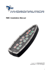
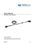
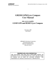
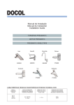
Ezy-DP Installation Manual
Osmotech UK
Hamble Point Marina
Hamble
Southampton
SO31 4NB
1. Table of Contents
Congratulations on your purchase of the Hydronautica EZY-DP system.
With this guide we will explain to you step by step how to skilfully and reliably build this
system, connect and use
2
Welcome
2.1
Installation of the EZY-DP
2.2
Mounting GH2183 GPS / Compass module
2.3
Mounting the PCB
2.4
Connecting the Ezy-DP
3
User Manual
3.1
Priority ranking between different systems
4
Annex
4.1
Appendix: Layout of the PCB
2. Welcome
The Hydronautica Ezy-DP system functions in conjunction with the RMC and Ezy
Dock modules.
If you already use an RMC in conjunction with the EZY-Dock system, the installation of
the Ezy-DP system is very simple. This guide takes you through the various stages to
install and operate a Ezy-DP system.
2.1 Installation of the Ezy-DP control
You need to decide whwre to place the positioning of these
pieces of equipment:
1 Drill holes Ø44mm
3. Drill Ø3,5mm
4. 2mm Allen key
Decide on the desired position of control panel.
Using the polished stainless steel ring mark out the
location.
Drill in the centre of the circle of a hole Ø44mm
Place the casing in the hole and rotate it
until the 4 small holes in a position that
you like
Mark these holes and drill these through with
drilling Ø3,5mm
Put the rubber seal on the dashboard. Then place the
housing again through the hole, in the right position.
Slide up the fastening ring at the bottom of the enclosure it, place the locking
ring on the top of the housing and pull the three parts together with the supplied
Allen screws m3.
Mounting the GPS/Compass sensor
The Ezy-DP uses an Airmar GH1283 GPS / Compass module connected to the EZYMaster.
The placement of this antenna requires some attention. Other devices can propagate
signals into the GPS and disrupt satellite reception.
Looking at the diagram below a position for the GH1283, which meets all requirements
with regard to possible confounding factors. Look at adjacent diagram for instructions
on installing the GH1283 Pull the cable from the module to the CPU box and plug it on
the board of the EZY-master.
Antenna Mounting Options
Pole or Rail Mount
The nut assembly supplied has standard marine 1"-14 TPI that can be
fitted to a standard marine antenna mount, extension pole, or rail-mount
bracket. Before beginning the installation, plan for securing the pole/rail bracket to
the selected mounting surface and purchase all the necessary hardware. It may
be helpful to fasten the pole/rail bracket in place before proceeding.
1. Remove the label from the sensor unit’s socket. Fasten the mount
base (part C) to the sensor unit (part A) with the two machine screws and lock
washers supplied. The torque for the screws is 1.35Nm.
2. Decide if you want the cable to exit through the center or along the side of the
pole/rail bracket. Slide the nut assembly onto the end of the cable at the sensor
connector. Do not connect the sensor at this time.
a. Centre exit—Pass the sensor connector end of the cable through the center
of the pole. Be sure to leave several inches of cable extending beyond the
nut assembly.
b. Side exit—Place the cable side-exit adaptor (part D) over the cable. Being
sure the cable is passing through the slot in the side, screw the nut assembly
onto the adaptor. Hand tighten only. Do not over tighten.
NOTE: Use the adaptor supplied as it has smooth edges that will not chafe the
cable. Do not use a purchased part.
3. Screw the extension pole/rail bracket onto the nut assembly /side-exit adaptor.
Hand tighten only. Do not over tighten.
4. Remove the protective cap from the sensor connector on the cable. (Save the
cap to protect the connector when the receiver is removed.) Plug the cable
firmly into the sensor.
5. With the alignment tab on the sensor facing forward and parallel to the
centerline of the boat / vehicle, slide the captive nut upward and screw it onto
the mount base. Hand tighten only. Do not over tighten.
Flush Mount
1. Remove the label from over the sensor unit’s socket (see Figure 3). Apply
removable thread locker to the two studs supplied. Screw the studs into the
underside of the sensor unit (part A).
2. Using the gasket (part B) as a template, position it at the selected mounting
location upside down with the arrow facing forward and parallel to the centerline
of the vehicle/boat. Mark the position of the two mounting holes and the center
hole for the cable.
3. Using a 3mm or 1/8" bit, drill the pilot holes. Using a 6mm or 1/4" bit, drill the two
mounting holes for the studs. Drill the cable hole with a 38mm drill or 1-1/2" hole
saw.
Fiberglass—Minimize surface cracking by running the drill in reverse until the
gel coat is penetrated.
4. Pass the sensor connector-end of the cable through the center of the gasket
and through the center mounting hole in the boat/vehicle.
5. Plug the cable firmly into the sensor unit.
6. Orient the gasket with the arrow facing in the same direction as the alignment tab
on the sensor unit. Push the gasket onto the studs and slide it over the connector.
NOTE: The gasket fits one way only. A groove in the gasket fits over the
alignment tab on the connector.
7. With the sensor’s alignment tab pointing forward and parallel to the centerline of
the boat/vehicle, push the studs through the mounting surface. Check to be
sure the gasket is tucked under the lip of the unit. From underneath the
mounting surface, slide a flat washer and lock washer onto each stud. Fasten
them with the thumb nuts. Hand tighten only. Do not over tighten.
NMEA Connections.
The EZY-Positioning system requires data from the antenna in the form of NMEA-0183. The
data connections are as below.
Power connection 9- 40VDC
GH2183 Antenna connections
to Ezy-DP PCB
NMEA 0183 out from antenna
Assembling the control box PCBs
Both the Ezy-DP and EZY-Pilot require additional PCBs installed in the main CPU
blue-box. In this circuit, the "EZY-master ', this GPS / compass connected. If you
already own a EZY-Pilot system, then it is already installed and you can skip this
section.
The next step in the installation is to add the EZY-Master board in the CPU box of the
RMC system. Make sure the system is completely disconnected before you start the
work ahead!
Screw the EZY-master with the four supplied screws firmly into the box.
See Appendix
Expand the power supply to the RMC connector.
Use the supplied power cable
Power looped to the RMC board.
Take the EZY dock board and place it on the RMC board like the pictures in the
Annex. Note be extremely careful to align holes and pins in the printed circuit boards
exactly align before pushing them together.
Connecting the Ezy-DP
Please note that the numbering of the compounds on the EZY Positioning are opposite
than the numbering on the circuit board., Both JP 3 as JP 4 can be used for this
purpose.
User Manual
When you have performed all previous steps it's time to test the system in use.
The Ezy-DP works only when the RMC system is running.
When the RMC system is running, you put the positioning standby for 2 seconds on
the right on / off button. When a usable GPS / Compass signal is present the green
LED will light up.
To activate positioning short press the left button
with the check mark. The system will now ensure
that the vessel remains at exactly the same position
To deactivate the Positioning momentarily press the
left button. For complete shutdown, you need the
right on / off button for 3 seconds
If the LED flashes red when the Pilot is activated,
it means that the system has no position lock.
Make sure the GPS / Compass module antenna is
connected correctly and has unobstructed sky view.
Priority ranking between different systems
If your vessel is equipped with an RMC system in combination with products from the
EZY/Ezy-DP series, certain systems have priority over others. In general, it applies
that the RMC is dominant.
The order shall be as follows:
1. RMC system. In use all the other systems are deactivated.
2. EZY dock. When using the joystick, both the pilot and the positioning are
deactivated
3. Ezy-DP.
Annex:
Lay-out of the RMC PCB:
Ezy Dock PCB
.
1.
Antenneaansluiting
Remote PCB
Master PCB
RMC PCB Parts List
1. Wireless remote antenna connection.
2. Wireless pairing button.
3. Line of 8 connectors. Numbers correspond with the buttons on the hand-held
RMC
4. Power supply connection. Note: The middle connector is common negative (0v)
The outside connectors are positive.
5. Potentiometers for adjusting the engine output signal. Adjust in conjunction with
pushing the corresponding control button.
6. Neutral connection.
7. Connector for the connection of a lever on the RMC foreign system.
8. Jumpers, remove it when you connect the RMC system on a non Hydronautica
lever.
9. Loop-through connector for an RMC plant in combination with a Hydronautica
EMC system.