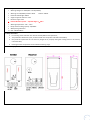
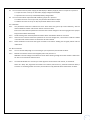
1
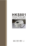
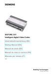
 Photocell beam sensor User Manual (P5101) 1 I. Technical Specification 1. Working voltage: 12~24VAC/DC or 3V Dry Battery 2. Working current(24VDC):emitter: ≤8mA receiver: ≤40mA 3. Photocell wavelength: 940nm 4. Angle of opposite emission: ≤±5º 5. Receiver range: ≥12m 6. Internal Rotation system adjusted Angle: 0~180 º 7. Working temperature: ‐20º~+60℃ 8. Relay contact loading capacity: 1A/30VDC 9. Waterproof grade: IP54 10. Size: 128*50*28mm II. Safety Instruction 1.
For security, please read the user manual carefully before initial operation; 2.
This photocell is without any fuse, so Please make sure the power is off before installation; 3.
Only used this system that do not cause any danger life or property during the running failure or its security risks eliminated; 4.
Please guarantee the products used in effective working range. III. Picture Display 2 IV. Installation instruction 4.1 You can choose external power supply (12‐24V AC/DC) or Battery supply by Latch or Jumper J2 in picture 3. 4.1.1 put the short circuit cap on Ext. Power, Supply voltage:12‐24V AC/DC 4.1.2put the short circuit cap on BATTERY, Battery voltage:3VDC 4.2 You can set the switch of photocell NO and NC by jumper J5 in picture 4. 4.2.1 when the short circuit cap on NO, The photocell will be Normal Open 4.2.2when the short circuit cap on NC, the photocell will be normal closed 4.3 Installation 4.3.1
The photocells should be installed more than 20cm above the ground (to avoid reflection), and the distance between emitter and receiver shall be more than 50cm. End user should install the photocell on the back of the direct sunlight or other strong light source (±5º) to keep photocell work well steadily. 4.3.2
Avoid installing other infrared photocell emitters within the effective distance of receiver 4.3.3
If the end user need to install other photocells in one same straight line , the receivers could be installed in the two ends and the emitters could be back‐to‐back installed 4.3.4
Stable installation could avoid the signal of emitter and receiver skewing due to lightly vibrate and the malfunction. 4.4 Wire connection 4.4.1
You can choose safety edge or not according to your requirement, PLS see PIC 5 & PIC 6. 4.4.2
PHOTO is the switch contact and changed by NO or NC, PLS see 4.2 LOW.BAT is the low voltage alarm switch to buzzer when working voltage of emitter module is lower than 2V. Also it can activate the external alarm. 4.4.3
You will find LED will turn on when you make alignment at the emitter and receiver, or led will off. When J5 is keep” NC”, alignment the emitter and receiver, LED will be on, photocell switch will work; if someone or something shelter the sensor, the Led will turn off, photocell switch will be does not work. 3 V Installation Pictures 1. Opening package
and taking out
accessories
2. Fixing the holder
location map on
wall
3. Drilling, and
fixing expansion
pipe
4. Connecting
lines
5. Fixing bottom
cover
6. Put upper
cover on
7. Screw bottom and
upper cover together
8.
Finished
4