1
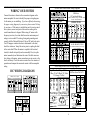
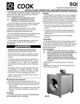
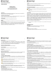
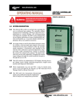
Installation &
Maintenance Manual
Techtop Canada Inc.
2-2795 Brighton Road
Oakville, ON L6H 6J4
www.techtop.com
[email protected]
________________________________________
Before you install, operate or perform maintenance,
become familiar with the following:
NEMA Publication MG-2: Safety Standard for Construction and
Guide for Selection, Installation and Use of Electric Motors.
IEC 60072-1 Electrical and IEC72-1 Mechanical specifications
ANSI C51.5, the National Electrical Code (NEC) and local codes
and practices.
OSHA standard 1910.147 titled: The Control of Hazardous energy
(lockout/tag-out).
RECIEVING
Once you receive your motor, instantly observe the condition of
the shipping container. Immediately report any damage to the
commercial carrier that delivered your motor.
Verify that the part number of the motor you received is the same
as the part number listed on your purchase order.
HANDLING
Use correct material handling equipment to avoid injury. Use
caution when removing the motor from its packaging. Sharp
corners may exist on motor shaft, motor key, sheet metal and other
surfaces.
SAFETY NOTICE
________________________________________
corners may exist on motor shaft, motor key, sheet metal and other
surfaces.
1. Connect Power and Ground to the motor according to NEC or
IEC and local codes.
2. Provide a permanent guard to prevent accidental contact of
body parts or clothing with rotating or moving parts of motor.
Beware of burns if motor is hot.
3. Shaft key must be secured before starting motor.
4. Mounting bolts should be high tensile steel. Be sure to use a
suitable locking device on each bolt (spring washer or thread lock
compound).
5. Do not apply power to the motor until the motor is securely
mounted by its mounting holes.
6. This motor must only be connected to the proper line voltage,
line frequency and load size.
7. Motors are not to be used for load holding or restraining unless
a properly sized brake is installed. If a motor mounted brake is
installed, provide proper safeguards in case of brake failure.
8. Disconnect all power services, stop the motor and allow it to
cool before servicing.
9. For single phase motors, discharge the start and/or run
capacitors before servicing.
10. Do not by-pass or render any inoperative safety devices.
GUARDING
Only qualified personnel, trained in the safe installation and
operation of this equipment, should install this motor. When
improperly installed or used, rotating equipment can cause
serious or fatal injury. Equipment must be installed in accordance
with the National Electrical Code (NEC), local codes and NEMA
MG2 Safety Standards for Construction and Guide for Selection,
Installation and Use of Electric Motors and Generators and OSHA
regulation standard 1910.147 titled: The control of hazardous
energy (lockout/tag-out).
Use correct material handling equipment to avoid injury. Use
caution when removing the motor from its packaging. Sharp
After motor installation is complete, a guard of suitable dimensions
must be constructed and installed around the motor. This guard
must prevent personnel from coming in contact with any moving
parts of the motor or drive assembly, but must allow sufficient
cooling air to pass over the motor. If a motor mounted brake is
installed, provide proper safeguards for personnel in case of brake
failure. WARNING: Guards must be installed to form a safe and
uncompromised perimeter around rotating parts such as couplings,
pulleys, external fans, and unused shaft extensions.
1
2
________________________________________
________________________________________
All parts should be permanently guarded to prevent accidental contact
by personnel. Accidental contact with body parts or clothing can
cause serious or fatal injury. When this motor is installed according
to these instructions, it complies with the EEC Machinery Directive.
Electromagnetic Compatibility (EMC) requirements for CE compliance
are met when the incoming power is purely sinusoidal.
or closed systems from which they can only escape through
accidental rupture or breakdown of such containers.
HAZARDOUS LOCATIONS
Ensure that the motor installed is proper for the location in which it
will operate. Division 2 motors should never be installed in locations
requiring a Division 1 motor. Familiarize yourself with the ratings
and the specific details of the motors working environment.
CLASS I: (Gases, Vapors)
Group A: Acetylene
Group B: Butadiene, ethylene oxide, hydrogen, propylene oxide
Group C: Acetaldehyde, cyclopropane, diethel ether, ethylene,
isoprene
Group D: Acetone, acrylonitrite, ammonia, benzene, butane,
ethylene dichloride, gasoline, hexane, methane, methanol, naphtha,
propane, propylene, styrene, toluene, vinyl acetate, vinyl chloride,
xylem
CLASS II (Combustible Dusts)
Group E: Aluminum, magnesium and other metal dusts with
similar characteristics.
Group F: Carbon black, coke or coal dust
Group G: Flour, starch or grain dust
Division 1: In which ignitable concentrations of hazards exists,
under normal operating conditions and/or where hazard is caused
by frequent maintenance or repair work or frequent equipment
failure.
Division 2: In which ignitable concentrations of hazards are
handled, processed or used, but are normally in closed containers
3
MOUNTING
Foot mounted: Foot mounted motors should be mounted to a rigid
foundation to prevent excessive vibration. Shims may be used if
the location is uneven. Improper alignment may void the motor’s
warranty.
Flange mounted: Flange mounted motors should be properly seated and aligned. Note: If improper rotation direction is
detrimental to the load, check the rotation or ‘bump’ the motor
prior to coupling the load to the motor shaft.
V-belt drive: Mount the sheave pulley close to the motor housing.
Allow clearance for end to end movement of the motor shaft. Do
not over tighten belts as this may cause premature bearing failure
or shaft breakage.
Direct coupled: Direct coupled motors should be carefully aligned
and the shaft should rotate freely without binding or drag.
NOTE: Techtop Motors with frame 254T and larger are
shipped with an opposite drive end bearing lock. If front end
bearing locks are desired, please contact Techtop for assistance.
GROUNDING
Ground the motor according to NEC and local codes. In the USA,
consult the National Electrical Code, Article 430 for information
on grounding of motors and generators, and Article 250 for general information on grounding. In making the ground connection,
the installer should make certain that there is a solid and permanent metallic connection between the ground point, the motor or
generator terminal housing, and the motor or generator frame. In
non-USA locations consult the appropriate national or local code
applicable.
4
________________________________________
NEMA Three Phase Motors Wiring Diagrams
WIRING YOUR MOTOR
3 Phase - YY/Y - 9 Lead
GR3 Motors
215T and Smaller Motors
Connect the motor as shown in the connection diagram on the
motor nameplate. Be sure to identify the proper wiring diagram
for the motor you are installing. If you have difficulty determining
the proper wiring diagram for your motor, please contact Techtop
for assistance. If this motor is installed as part of a motor control
drive system, connect and protect the motor according to the
control manufacturer’s diagram. When using AC motors with
frequency inverters, be certain that the motors maximum speed
rating is not exceeded. The wiring, fusing and grounding must
comply with the National Electrical Code or IEC and local codes.
Note: If improper rotation direction is detrimental to the load,
check the rotation or ‘bump’ the motor prior to coupling the load
to the motor shaft. When the motor is coupled to the load and
started, it should start quickly and run smoothly. If not, stop the
motor immediately and determine the cause. Possible causes are:
low voltage at the motor, motor connections are not correct or the
load is too heavy. Check the motor current after a few minutes of
operation and compare the measured current with the nameplate
rating.
V2
W2
U2
V2
W2
W2
W4
U2
U4
V2
V4
U2
U4
V2
V3
W2
W3
U3
V3
W3
U3
V3
W3
U3
V3
W3
W4
U4
V4
U1
V1
W1
U1
V1
W1
U1
V1
W1
U1
V1
W1
LOW VOLTAGE HIGH VOLTAGE
U2
4
5
6
7
8
9
7
8
9
12
10
11
12
10
11
1
2
3
1
2
3
U2
V2
V1
U1
W1
5
V1
W1
6
4
5
6
7
8
9
7
8
9
1
2
3
1
2
3
LOW VOLTAGE HIGH VOLTAGE
All 3 Phase - Single Voltage
ALL OR3 - GR3 & BL3 (575, 460V)
CONNECTIONS
5
4
5
6
10
11
12
7
8
9
7
8
9
4
5
6
12
10
11
12
10
11
7
8
9
1
2
3
1
2
3
1
2
3
460V RUN
230V RUN
796V RUN
T1 & T4: Blue / T2 & T5: White / T3 & T6 Orange
1,2,3 Top - 4,5,6 Bottom
215T and
Smaller Y
1
2
3
L1
L2
L3
6
4
5
1
2
3
L1
L2
L3
NEMA Single Phase Motor Wiring Diagrams
T2
T5
T3
T2
T5
T3
P1
T4
T8
P1
T4
T8
L1
L2
P2
L1
L2
P2
Single Phase Single Voltage
RD1 Line- Frame 182T-215T
BLUE
31
BLACK
WHITE
ORANGE
BLACK
BLACK
P1
P2
T5
BLACK
T2
BLUE
T3
T8
MAIN 2
T4
182/4T
BLUE
213/5T
Interchange T1 T8 P2 T8
T5 and T8
T5
T5
to Reverse P1 T4 P1 T4
Rotation
L1 L2 L1 L2
High Voltage
Low Voltage
YELLOW
U1
5
4
MAIN 1
W2
4
6
2
V2
CONNECTIONS
Low Voltage High Voltage
BLUE
132 and
Smaller Y
W2
5
T8
Leads may
not be color
coded
T5
AUX
U2
3 Phase - Single Voltage
4
Single Phase Dual Voltage-RD1 Line
P: Blue / P2 & T5: Black / T2: White
T3: Orange / T8: Red
3 Phase - YY/Y - 9 Lead
GR3 Motors 132 and Smaller Motors
LOW VOLTAGE HIGH VOLTAGE
CONNECTIONS
6
AUX
IEC WIRING DIAGRAMS
4,1 Blue / 5,2 White / 6,3 Org / 7 Yl / 8 Blk / 9 RD
1,2,3 Top - 4,5,6,7,8,9 Bottom
1
RED
2
3
Interchage T5 and T8 to Reverse Rotation
6
MAIN 2
213/5T Only
182/4T Only
P1
P2
T1
T4
_____________________________________________
________________________________________
WARNING: Do not touch electrical connections unless you first ensure
that power has been disconnected. Please refer to: OSHA standard
1910.147 titled: The Control of Hazardous energy (lockout/tag-out).
8. Install grease drain plug located opposite the grease inlet.
WARNING: Surface temperatures of motor enclosures may reach temperatures which can cause discomfort or injury to personnel coming in contact
with hot surfaces. Protection should be provided by the user to protect
against accidental contact with hot surfaces. Failure to observe this precaution could result in bodily injury.
LUBRICATION PROCEDURE
Caution: Keep grease clean. Mixing dissimilar grease is not recommended
and may result in premature bearing failure.
1. Re-lubrication is recommended when the motor is warm and the shaft is
stationary.
2. Remove all dirt and wipe the outside of the grease fills and drains.
3. Clean the grease fitting (or area around grease hole, if equipped with
slotted grease screws). If the motor has a purge plug, remove it. Motors can
be re-greased while stopped (at less than 80°C) or while running.
4. When applicable, locate the grease inlet at the top of the bearing hub. If
the motor is not equipped with grease fitting, clean the area and replace the
1/8-inch pipe plug with grease fitting.
5. Remove grease drain plug located opposite the grease inlet.
6. Apply grease gun to fitting (or grease hole). Too much grease or injecting grease too quickly can cause premature bearing failure. Slowly apply
the recommended amount of grease, taking a few minutes or so to apply.
7. Operate the motor for 20 minutes and reinstall the purge plug if previously removed.
7
SUGGESTED LUBRICATION INTERVALS
NEMA Frame RPM
DUTY
INTERVAL
210-360
1800 or less
standard
2 years
210-360
1800 or less
severe
1 year
210-360
> 1800
standard
6 months
210-360
> 1800
severe
3 months
400-510
1800 or less
standard
1 year
400-510
1800 or less
severe
6 months
400-510
> 1800
standard
3 months
400-510
> 1800
severe
1 month
SUGGESTED LUBRICANT VOLUME
NEMA frame
Volume (Cubic in)
Volume fluid ounces
250
1.00
.55
280
1.25
.69
320
1.50
.83
360
1.75
.97
400
2.25
1.2
440
2.75
1.5
500
3.00
1.7
MAXIMUM SIDE LOADING
When application calls for significant side loading of the motor, the
application may require roller bearings to avoid early life failure
of motor.
8
________________________________________
Properly asses the resultant side load before installing your motor.
If your side load exceeds the value shown in the table, please
contact Techtop to explore options for use of roller bearings.
Allowable Side Load for Ball Bearing Motors
Frame Size
143T
145T
182T
184T
213T
215T
254T
256T
284T
286T
324T
326T
364T
365T
404T
405T
444T
445T
447T
449T
3600 RPM
106
109
180
180
230
230
470
470
570
570
660
660
820
820
1800 RPM
154
154
227
227
300
300
593
589
735
735
860
850
1080
1080
1270
1290
1560
1520
1450
1490
1200 RPM
179
176
260
260
350
350
703
705
838
838
990
980
1240
1240
1450
1480
1760
1760
1660
1660
If the application calls for significant thrust loads, please contact
Techtop to determine if you have the correct motor for your
application.
9
________________________________________
NOTES
1. Overhung loads are considered to include belt tension and
sheave weight.
2. Belt loads considered to act in a vertically downward direction.
3. To determine load at shaft end subtract 15%.
4. Overhung load radial limits are based on a bearing L-10 life of
26,280 hours.
5. Overhung load limits don’t include effects of any unbalanced
magnetic pull.
CONDENSATE DRAINS
Many Techtop motors come standard with one way sintered brass
breather drains. These drains allow the motor to expel liquids from
the casing without allowing liquid to enter the motor. Drains may
require periodic maintenance to keep them clean of debris and
flowing freely. Occasionally, remove the brass drains and wash
them thoroughly. Eliminate any built up debris which may be
impeding their operation.
For motors which are equipped with rubber plugs in their
condensate drain holes, be sure to remove the plug (i.e. especially
if the motor is installed in a location where condensate build up is
likely).
In all instances, ensure that the drain is in the lowest portion of the
motor. Some motors may require rotation of the end plates (i.e. if
the mounting location is not a typical horizontal mounting).
SEAL REPLACEMENT
Inspect seals regularly for excessive wear which could lead to
bearing failure. If significant wear is present, please contact
Techtop for replacement seals.
10