1
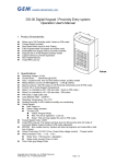
DG-15 series Digital Keypad Entry system Operation User's Manual 1. Specifications: Operating Voltage: 12 Vdc Current Draw: Average 15mA, Peak 100mA @ 12Vdc Input: request-to-exit, time out reed switch contact Output: Dual relays, N.O./N.C./Com. Output (free voltage contact) Relays Electric Current: 2A MAX @30Vdc ;0.4A @ 120Vac Relay Activation Time: Relay 1 time delay setting code「*30」、Relay 2 setting code「*31」 Strike Time: 1~99 seconds(adjustable) Strike mode: Access Timer or Latch Memory Volume: 20+1 PIN codes Relay 1 is controlled by *01~*20 user slots Relay 2 is controlled by *21 user slots Operating Temperature: -20~+70℃ Ambient Humidity: 5~95% relative humidity non-condensing Factory Master Code: 12345 Invalid PIN Lock-out: The system will shut down for 60 seconds while 30 codes of incorrectly Master Codes enrolled or PIN codes attempted(None beeper signal of keypad activations). EPROM: Non-volatile memory, System will retain all programs and codes after a total loss of power. The indicator signal chart: LED signal Sound signal Green LED Power on, stand-by 1 Beep Effective PIN codes、Any key pressed Red LED Relay 1 activated 2 Beeps Entering 、Exiting from the Program mode Yellow LED Relay 2 activated 3 Beeps Data computing error 5 Beeps Master Code reset to Factory (12345) 2. Operation Instruction: Enter Program Mode: 1. Compose twice the master code (4 digit format press「1234」、5 digit format press 「12345」) → 2 beeps → you are now in the "programming mode". 2. After 60 seconds if you have not entered any codes or data, the system will automatically exit from the programming mode. Exiting from the program mode: 1. Press「#」 to exit from the programming mode. 2. After 30 wrong codes attempts at the master code the lockout facility will operate. Add PIN codes Enter the Programming mode, Enter the slot position code 「*01~*20」→????? Input 5 digit (or 4 digit)PIN codes→ (beep) enrolled Æ(repeat) Press 「#」 to exit from the programming mode, or program other operating. Note 1: The codes「0000」,「00000」,「1234」,「12345」or master code are not be used for PIN code. Note 2: Relay 2 is controlled by *21 user slots To Delete a User Code: Copyright Gianni Industries, Inc. All Rights Reserved. P-MU-DG15 Ver. B Publish:2008.08.01 Page: 1/ 2 Enter the Programming mode→ Press the slot position code of your choice to delete (example "06") →Press「*06」→「0000」(or「00000」)→(beep)→delete→ Press「#」 to exit from the programming mode, or programming other operating. To Program Relocking Timer Enter the Programming mode, A. Relay 1:Press「*30」Followed by the number of seconds the relay should open→「05」=5 seconds(01 ~99 = seconds,「00」Sets the relay to latching mode)→(beep)→enrolled → Press 「#」 to exit from the programming mode, or program other operating. B. Relay 2:Press「*31」Followed by the number of seconds the relay should open)→「05 =5 seconds (01 ~99 = seconds,「00」Sets the relay to latching mode). →(beep)→enrolled → Press 「#」 to exit from the programming mode, or program other operating. C. Latching mode: Correct code entered opens the relay, and the relay stays open until the correct code is entered again. Changing the Master codes: Enter the Programming mode, Enter「*00」Followed by the new 4 digit (or 5 digit) master code→(beep)→enrolled→Enter 「#」 to exit from the programming mode, or program other operating. Master Code reset to Factory 「12345」 Insert the RESET jumper resetting positionÆ5 audible beepsÆReset successfulÆ Return Insert the jumper to normal position. 3. Wiring diagram: Fail-Safe Locking Device 2 Power Supply Relay 2 Relay 1 Push Button Contact door reed switch This reed switch is used to reset the re-locking time to 0 second when the door is moved. 4OR5 RESET Master Code resetting to Factory Code"12345" System 4 or 5 digit code setting 4 digit 5 digit 4OR5 RESET Resetting Normal Note: The suggested wire gauge is #22~26 AWG. The varistor or diode must be connected across the lock terminal (electromagnet...) operated by the device. The vartistor controls the overload produced by the strike coil (EMP). Egresses switch should be N.O. type. REED contact input for anti-trailing(Relay 1). Contact door reed switch, this reed switch is used to reset the re-locking time to 0 second when the door is moved. Using N.O. contact in case of door closed changeover to N.C. When door is moved. Copyright Gianni Industries, Inc. All Rights Reserved. P-MU-DG15 Ver. B Publish:2008.08.01 Page: 2/ 2