1
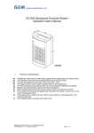
DG-700 Stand alone Access Controller
Operation User's Manual
Specifications:
z
z
z
z
z
z
z
z
z
z
z
z
z
Input: Request-to-exit
Relay Electric Current: 3A MAX@30Vdc /
3A@120Vac
Operating Voltage: 10~15VDC
Operating Temperature: -5~60℃
Memory Volume: 65000 Proximity cards
Keyboard: 12 digits keypad (0,9,*,#)
Waterproof Design: Waterproof Type Key Pads
Transmitting Frequency: 125K
Visual Signals: LED (RED, BLUE AND GREEN)
Relocking timer: 1~255 Seconds
Read Range: Up to 10 cm (Depending on local
installation conditions)
Size: 110(H)x76(W)x23.5(D)mm
Ambient Humidity: 5%~95%
Master Card Function
z
First set a master card. These cards can then be used to enter programming mode
directly.
Sound and LED indicator:
Mode
Setting
Standby Mode
Signal
Condition
Blue LED+Bi once
Setting Successful
Red LED+Bi twice
Fail
Blue LED Flash every 0.1 sec.
In Security Setup Mode
Blue LED Flash every 0.5 sec.
All cleared, Normal Operation Mode
Blue LED Flash every 2 sec.
In Data Processing Mode
Red LED(Flashing)
Start Alarm Function
Red LED+Blue LED(Flashing)
Press *99 (5 Beeps), cancel Alarm
If not set within 30 seconds it automatically exit the setting mode
Blue LED
Power on, Stand-by
Red LED
Operation mistake
Green LED
Valid Access
Default Settings
Access Mode
Read Card only
Card register
Master Codes
Alarm function
Relocking timer
Setting mode delay time
None
123456
Defeat able (000)
3 seconds
30 seconds
WIRING
Wire
1
2
3
4
5
Color
Wire Application
Pink
LED
Blue
Gray Beeper
Yellow
Wiegand
Orange
Connector - 6P Color Coding
Description
LED Red output 5V/20ma,Max
LED Blue output 5V/20ma,Max
Beeper output 5V/50ma,Max
Wiegand D0 input
Wiegand D1 input
Copyright Gianni Industries, Inc. All Rights Reserved.
P-MU-DG-700 Ver. B Publish:2006.02.08
Page: 1
Wire
1
2
3
4
5
6
7
8
Color
Purple
Green
White
Pink
Brown
Gray
Black
Red
Wire Application
Door Relay
Door Sensor
Exit switch
Alarm Output
Power
Connector-8P Color Coding
Description
(N.O.) DC24V1Amp
(N.C.) DC24V1Amp
(COM.) DC24V1Amp
Negative Trigger input
Negative Trigger input
Transistor output (open Collector Active Low) Max 12v/100ma
DC Power 0 V
DC Power 12 V
Connector - 3P Color Coding
Wire Color Wire Application
Description
1
Green
N.O.
2
White Tamper Switch COM.
3
Purple
N.C.
Enter Programming
Press *123456 # (Default Master Code 123456). The blue LED will now flash rapidly (You
are now in programming Mode)
Changing The Master Code
Show Master Card
Enter 01*?????? + ?????? #
?????? = New master code which is entered twice
Show master to exit programming.
Set & Add Master Tokens
Enter programming mode
Enter 25 * N # (N= Number of master cards required 1 or 2.) → Show proximity device to
register master cards.→ One long beep followed by a short beep confirms registration.
Exit Programming
Press * # ( you have now exited programming mode). You can now enter programming
mode by just using the master cards. Show master card (You are now in programming, blue
LED flashing rapidly)
Adding User Cards / Tokens
Show Master Card→ Show card to be added→ Show next card to be added→ Show Master
to exit programming.
Deleting User Cards / Tokens
Show Master Card→ Show card to be deleted→ Show next card to be deleted→ Show
Master to exit programming.
To delete a non-present card you require the optional TAG SIMULATOR unit.
Adjusting The Lock Relay Time
Show Master Card
Enter 03* ??? # (??? = Number of seconds required 001 =1 sec. Max 255=255 sec.)
By entering 000 the lock timer will set to toggle. Toggle = show a user card relay opens, and
stays open until another. user card is shown. Show master to exit programming.
Deleting All User Cards / Tokens
Show Master Card→ Enter 15* 99 #→ Show Master to exit programming.
Copyright Gianni Industries, Inc. All Rights Reserved.
P-MU-DG-700 Ver. B Publish:2006.02.08
Page: 2
Copyright Gianni Industries, Inc. All Rights Reserved.
P-MU-DG-700 Ver. B Publish:2006.02.08
Page: 3
Copyright Gianni Industries, Inc. All Rights Reserved.
P-MU-DG-700 Ver. B Publish:2006.02.08
Page: 4