1
KRAMER ELECTRONICS, Ltd.
USER MANUAL
Distribution Amplifiers Models:
VM-1010, VM-1015, VM-1021,
VM-1042, VM-1044, VM-1055, VM-54
IMPORTANT: Before proceeding, please read paragraph entitled
"Unpacking and Contents"
KRAMER ELECTRONICS LTD.
Table of Contents
Section
Name
1
1.1
1.2
2
3
4
4.1
5
5.1
5.2
5.3
5.4
5.5
5.6
5.7
6
6.1
7
8
8.1
8.2
8.3
8.4
8.5
8.6
8.7
9
10
10.1
10.2
INTRODUCTION
A Word On Distribution Amplifiers
Factors Affecting Quality of Results
SPECIFICATIONS
HOW DO I GET STARTED?
UNPACKING AND CONTENTS
Optional Accessories
VM SERIES AMPLIFIERS
Getting To Know Your VM-1010 Amplifier
Getting To Know Your VM-1015 Amplifier
Getting To Know Your VM-1021 Amplifier
Getting To Know Your VM-1042 Amplifier
Getting To Know Your VM-1044 Amplifier
Getting To Know Your VM-1055 Amplifier
Getting To Know Your VM-54 Amplifier
INSTALLATION
Rack Mounting
CONNECTING TO VIDEO DEVICES
USING THE VIDEO AMPLIFIERS
Powering On The Amplifier
Looping
Level Control
Equalization Control
Coupling
Black Level Clamping
Sync Tip Clamping
TAKING CARE OF YOUR VIDEO AMPLIFIER
TROUBLESHOOTING
Power And Indicators
Video Signal
Limited Warranty
List Of Illustrations
Figure
1
2
3
4
5
6
7
VM-1010 Front/Rear Panel Features
VM-1015 Front/Rear Panel Features
VM-1021 Front/Rear Panel Features
VM-1042 Front Panel Features
VM-1044 Front/Rear Panel Features
VM-1055 Front/Rear Panel Features
VM-54 Front/Rear Panel Features
VM-1010 Front Panel Features
VM-1010 Rear Panel Features
VM-1015 Front Panel Features
VM-1015 Rear Panel Features
VM-1021 Front Panel Features
VM-1021 Rear Panel Features
VM-1042 Front/Rear Panel Features
VM-1044 Front/Rear Panel Features
VM-1055 Front/Rear Panel Features
VM-54 Front Panel Features
VM-54 Rear Panel Features
Signals Supported By Model
KRAMER ELECTRONICS LTD.
1
1
2
3
4
4
4
5
5
6
7
9
10
11
12
14
14
15
15
15
15
16
16
17
17
17
17
18
18
18
20
Page
5
6
7
9
10
11
12
List Of Tables
Table
1
2
3
4
5
6
7
8
9
10
11
12
Page
Page
5
6
7
7
8
8
9
11
12
13
14
15
i
INTRODUCTION
Congratulations on your purchase of this Kramer Electronics amplifier. Since 1981 Kramer
has been dedicated to the development and manufacture of high quality video/audio
equipment. The Kramer industrial line has become an integral part of many of the best
production and presentation facilities around the world. In recent years, Kramer has
redesigned and upgraded most of the industrial line, making the best even better. Kramer’s
line of professional video/audio electronics is one of the most versatile and complete
available, and is a true leader in terms of quality, workmanship, price/performance ratio
and innovation. In addition to the Kramer line of high quality amplifiers, such as the one
you have just purchased, Kramer also offers a full line of high quality industrial and
broadcast switchers, processors, interfaces, controllers and computer-related products.
Kramer welcomes your inquiries for Kramer equipment or custom-manufactured products,
engineering, private labeling and OEM manufacturing per your specifications.
This manual includes configuration, operation and information for the following products
from the Kramer VM line of distribution amplifiers. All these VM amplifiers are similar in
operation and features.
VM-1010 - 1:10 Video Distributor
VM-1015 - 1:5 Video Distributor
VM-1021 - 1:20 Video Distributor
VM-1042 - 4:2 Video Component Distributor
VM-1044 - 4:4 Video Distributor
VM-1055 - 1:5 Five Channel Video Component Distributor
VM-54 - Looping Video Distributor
A Word On Distribution Amplifiers
Distribution amplifiers are used to distribute one source to several acceptors for
simultaneous recording or monitoring of one source, with no discernible signal
degradation. They vary in the number of inputs, looping capability, programming
capability, number of outputs, operating format, bandwidth and input/output coupling. A
good quality distribution amplifier amplifies the incoming signal, pre-compensates the
signal for potential losses (resulting from the use of long cables, noisy source, etc.) and
generates several identical buffered and amplified outputs. Often, a signal processor is
inserted between the source and the distribution amplifier for correction and fine-tuning of
the source signal before multiplication, so that all copies are corrected in the same way.
The front panels of these Kramer amplifiers are designed to be simple to operate.
KRAMER ELECTRONICS LTD.
1
Factors Affecting Quality of Results
There are many factors affecting the quality of results when signals are transmitted from a
source to an acceptor:
Connection cables - Low quality cables are susceptible to interference, they degrade signal
quality due to poor matching and cause elevated noise levels. They should therefore be of
the best quality.
Sockets and connectors of the sources and acceptors - So often ignored, they should be of
highest quality, since "Zero " connection resistance is the target. Sockets and connectors
also must match the required impedance (75 in video). Cheap, low quality connectors
tend to rust, thus causing flaws in the signal path.
Amplifying circuitry - Must have quality performance when the desired end result is high
linearity, low distortion and low noise operation.
Distance between sources and acceptors - Plays a major role in the final result. For long
distances (over 15 meters) between sources and acceptors, special measures should be
taken in order to avoid cable losses. These include using higher quality cables or adding
line amplifiers.
Interference from neighboring electrical appliances - These can have an adverse effect on
signal quality. Balanced audio lines are less prone to interference, but unbalanced audio
should be installed far from any mains power cables, electric motors, transmitters, etc.
even when the cables are shielded.
KRAMER ELECTRONICS LTD.
2
SPECIFICATIONS
VM-1010
VM-1015
VM-1021
VM-1042
VM-1044
VM-1055
VM-54
Configuration
2X CV
1X CV
1X CV
4XCV/RGB
4XCV/RGB
5XCV/ RGB
HSVS
1X CV, 3comp
Input Type
CV
CV
CV
CV/RGB
CV/RGB
CV/RGB HSVS
CV/Comp
Input
Connections
BNC
BNC
BNC
BNC
BNC
BNC
BNC
Input Level
1Vpp/75
looping
1Vpp/75
looping
1Vpp/75
looping
1Vpp/75
looping
1Vpp/75
1Vpp/75
1Vpp/75
looping
Output Type
1X10 or 2X5
5XCV
CV 3Vpp Max.
2X4 CV/RGB
2Vpp
4X4 CV/RGB
5X5CV/ RGB
HSVS
3x18
Composite/ CV
Output
Connector
BNC
BNC
BNC
BNC
BNC
BNC
BNC
Output Level
1Vpp/75
1Vpp/75
1Vpp/75
1Vpp/75
1Vpp/75
1Vpp/75
1Vpp/75
Output
Coupling
DC/AC
AC/ DC/
Clamped
AC/ DC/
Clamped
DC
DC
DC
DC/AC
S/N Ratio
74dB
75dB
74dB
73dB
74dB
74dB
70dB
Bandwidth
220MHz –3dB
340MHz -3dB
350 MHz -3dB
200 MHz -3dB
320 MHz -3dB
300 MHz -3dB
350MHz
Differential
Gain
0.05%.
0.08%.
0.1%.
0.05%.
0.05%.
0.1%.
0.03%
Differential
Phase
0.05Deg
0.12Deg
0.07Deg
0.05Deg
0.05Deg
0.1Deg
0.09Deg
K-Factor
<0.05%.
<0.03%.
<0.03%.
<0.05%.
0.1%.
0.05%.
<0.05%
Non Linearity
0.2%
<0.1%.
0.1%.
<0.1%.
<0.1%.
0.1%.
0.2%
EQ. Control
0 to 2.5dB @
100% color bar,
4.43MHz
0 to 2.7dB @
100% color bar,
4.43MHz
0 to 2.9dB @
100% color bar,
4.43MHz
0 to 1.3dB @
100% color bar,
4.43MHz
0 to 0.9dB @
100% color bar,
4.43MHz
No equalization
0 to 2.3dB
DC Clamp
Not clamped
0 V DC Black
Level, or sync
bottom TIP
0 V DC Black
Level, or sync
bottom TIP
Not clamped
Not clamped
Not clamped
Not clamped
Level Control
-1.4dB to
+2.5dB
-1.2dB to
+2.8dB
(trimmer)
4 accessible
trimmers
-2.2dB to
+2.0dB
-1.1dB to
+2.5dB
Fixed gain=1
24 accessible
trimmers
Dimensions
19” (W), 7” (D),
1U (H)
48.26 cm x
17.78 x 4.5cm
19” (W), 7” (D),
1U (H)
48.26 cm x
17.78 x 4.5cm
19” (W), 7” (D),
1U (H)
48.26 cm x
17.78 x 4.5cm
19” (W), 7” (D),
1U (H)
48.26 cm x
17.78 x 4.5cm
19” (W), 7” (D),
1U (H)
48.26 cm x
17.78 x 4.5cm
19” (W), 7” (D),
1U (H)
48.26 cm x
17.78 x 4.5cm
19” (W), 7” (D),
2U (H)
48.26 cm x
17.78 x 9 cm
Weight
2.5kg (5.55lb)
Approx.
2.42kg (5.38lb)
approx.
2.66kg (5.91lb)
approx.
2.5kg (5.55lb)
approx.
2.54kg (5.64lb)
approx.
2.66kg (5.91lb)
approx.
3.98kg (8.84lb)
approx.
Power
consumption
Power Source
10.3VA
4.6VA
6.7VA
3.2VA
4.6VA
5.3VA
21.39VA
230V/115V AC
50/60Hz
230V/115V AC
50/60Hz
230V/115V AC
50/60Hz
230V/115V AC
50/60Hz
230V/115V AC
50/60Hz
230V/115V AC
50/60Hz
230V/115V AC
50/60Hz
KRAMER ELECTRONICS LTD.
3
HOW DO I GET STARTED?
The fastest way to get started is to take your time and do everything right the first time.
Taking 15 minutes to read the manual may save you a few hours later. You don’t even
have to read the whole manual. At the beginning of each section, you’ll find an overview
of the section. So if the section doesn’t apply to you, you don’t have to spend your time
reading it.
UNPACKING AND CONTENTS
The items contained in your Kramer VM Amplifier packaging are listed below. Please save
the original box and packaging materials for possible future transportation and shipment of
the Amplifier.
Amplifier (rack-mountable)
AC power cable
User Manual
4 rubber feet
For additional information regarding optional cables and optional accessories contact your
Kramer dealer.
Optional Accessories
The following Kramer accessories can enhance implementation of your amplifier.
SP-11 - (Video/Audio Processor) can be serially connected between the video/audio source
and the VM amplifier for video and audio control/correction. The machine provides camera
control and luminance/white balance correction. The SP-11 is also capable of performing
Composite to Y/C conversion and bi-directional transcoding. The machine allows full control
over the video signal: Video gain down to full fade, log or linear Definition control, log or
linear Contrast control, Color saturation control, Black Level control, Red, Green and Blue
controls and a Screen Splitter control for “before-after” comparison. The Input switch control
is "Audio-follow-Video".
SP-3001 - (Component Video Processor) can be serially connected to the VM amplifier in
order to achieve full control of component video. The SP -3001 has 3 looping Component
Video inputs and 9 outputs- three for each component; thus it serves as a Component DA as
well. The SP -3001 allows full control of Gain, Contrast, Definition and black level of the Y
channel and individual Gain and Black level controls of the R-Y and B-Y channels. A Screen
Splitter control for "before-after" comparison is also built in.
611T/611R - (611T full bandwidth Fiber Optic Transmitter and 611R matching Fiber Optic
Receiver) Part of the KRAMER TOOLS series, and designed for studio and other demanding
applications. These machines, in combination, may be used to send one of the distributed
channels to distances of 5-25Km. The 611T and 611R use state-of-the-art fiber optic circuitry
and allow the user (via rear panel trimmers) to adjust input and output video levels and high
frequency peaking to achieve best performance. Both machines, like all KRAMER TOOLS,
are fed from a 12V DC source, making them perfectly suitable for fieldwork as well.
KRAMER ELECTRONICS LTD.
4
VIDEO TESTER - A new, unique, patented, indispensable tool for the video professional,
the Video Tester is used to test a video path leading to/from an amplifier. By pressing only one
touch switch it can trace missing signals, distinguish between good and jittery (VCR sourced)
signals, and identify the presence of good signals. Whenever a video signal is missing, because
of bad connections, cable breaks or faulty sources, the Video Tester is all you need.
VM SERIES AMPLIFIERS
This section describes all the controls and connections of your amplifier. Understanding all
of the controls and connections helps you realize its full power.
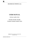
Getting To Know Your VM-1010 Amplifier
The KRAMER VM-1010 is full broadcast, state-of-the-art, Programmable Video
Distribution Amplifier designed for studio and other demanding applications. The VM1010 has two looping video inputs, each splitting to 5 outputs. The user may select 2x1:5
or 1:10 operation via front panel control switches. Several VM-1010 units may be chained
through the looping inputs. Output signals are (user selectable) DC or AC coupled for
maximum flexibility.
Front/rear panel features of the VM-1010 are described in Figure 1, Table 1 and Table 2.
Figure 1: VM-1010 Front/Rear Panel Features
Table 1: VM-1010 Front Panel Features
No.
Feature
1.
Power switch
Illuminated switch: Supplies power to the unit.
2.
EQ trimmer (CHANNEL B)
Controls cable equalization of channel B outputs.
3.
Level trimmer (CHANNEL B)
Controls video level of channel B outputs.
4.
MODE (2 x 1:5, 1:10) pushbutton
Selects either 1:10 or 2 x 1:5 operation.
5.
EQ trimmer (CHANNEL A)
Controls cable equalization of channel A outputs.
6.
Level trimmer (CHANNEL A)
Controls video level of channel A outputs.
KRAMER ELECTRONICS LTD.
Function
5
Table 2: VM-1010 Rear Panel Features
No.
Feature
Function
1.
OUT 1A -5A BNC connectors
5 amplified and buffered video outputs.
2.
INPUT A BNC connector
Video input.
3.
75
Selects "75 " or "HI-z" impedance (for looping select "Hiz").
4.
DC pushbutton
Selects DC coupling when pushed.
5.
LOOP BNC connector
Provides video looping capability to increase number of
outputs.
6.
INPUT B BNC connector
Video input.
7.
75
Selects "75 " or "HI-z" impedance (for looping select Hiz).
8.
DC pushbutton
Selects DC coupling when pushed.
9.
LOOP BNC connector
Provides video looping capability to increase number of
outputs.
10.
OUT 1B –5B BNC connectors
5 amplified and buffered video outputs.
11.
Power Connector
A 3-prong AC connector allows power to be supplied to the
unit. Directly underneath this connector, a fuse holder houses
the appropriate fuse.
pushbutton
pushbutton
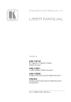
Getting To Know Your VM-1015 Amplifier
The KRAMER VM-1015 is a full broadcast, state-of-the-art 1:5 Video Distribution
Amplifier designed for studio and other demanding applications. The VM-1015 splits a
single input source into five identical outputs with no discernible signal degradation.
Output signals can either be AC or DC coupled, black level or sync tip (signal bottom)
clamped, thus allowing the machine to function in all video environments. The machine
may be used to distribute analog or SDI (Serial Digital) video signals, composite or single
component. Video bandwidth of well over 340MHz and superb specifications make the
VM-1015 the ultimate distributor for all video applications.
Front/rear panel features of the VM-1015 are described in Figure 2, Table 3 and Table 4.
Figure 2: VM-1015 Front/Rear Panel Features
KRAMER ELECTRONICS LTD.
6
Table 3: VM-1015 Front Panel Features
No.
Feature
1.
Power Switch
Illuminated switch: Supplies power to the unit.
2.
EQ trimmer (ADJUST)
Controls cable equalization of the video outputs.
3.
LEVEL trimmer (ADJUST)
Controls video level of the video outputs.
4.
DC (COUPLING) switch
Selects DC coupling when pushed.
5.
AC (COUPLING) switch
Selects AC coupling when pushed.
6.
BLACK (CLAMP) switch
Clamps video signal to the black level when pressed (best used
for Composite or Component video).
7.
TIP (CLAMP) switch
Clamps video signal to the sync tip (signal bottom) level when
pressed (best used for RGB signals).
Function
Table 4: VM-1015 Rear Panel Features
No.
Feature
Function
1.
INPUT BNC connector
Video input
2.
TERM pushbutton
Selects “75 “ or “HI-z” impedance when pressed (for looping
select "Hi-z").
3.
LOOP BNC connector
Provides video looping capability to increase number of outputs.
4.
OUT 1-5 BNC connectors
5 amplified, buffered and clamped video outputs.
5.
Power Connector
A 3-prong AC connector allows power to be supplied to the
unit. Directly underneath this connector, a fuse holder houses
the appropriate fuse.
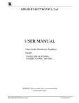
Getting To Know Your VM-1021 Amplifier
The KRAMER VM-1021 is a full broadcast, state-of-the-art, 1:20 Video Distribution
Amplifier designed for studio and other demanding applications. The VM-1021 splits a
single input source into twenty identical outputs with no discernible signal degradation.
Output signals can either be AC or DC coupled, black level or sync tip clamped, thus
allowing the machine to function in all video environments. The outputs are divided into 4
sets of five each, where each set may be individually trimmed (level and EQ) for maximal
flexibility. The machine may be used to distribute analog or SDI (Serial Digital) video
signals, composite or single component. Video bandwidth of well over 350MHz and
superb specifications make the VM-1021 the ultimate distributor for all video applications.
Front/rear panel features of the VM-1021 are described in Figure 3, Table 5 and Table 6.
KRAMER ELECTRONICS LTD.
7
Figure 3: VM-1021 Front/Rear Panel Features
Table 5: VM-1021 Front Panel Features
No.
Feature
1.
Power Switch
Illuminated switch: Supplies power to the unit.
2.
EQ trimmer (SET 4 ADJUST)
Controls cable equalization of SET 4 video outputs.
3.
LEVEL trimmer (SET 4 ADJUST)
Controls level of SET 4 video outputs.
4.
EQ trimmer (SET 3 ADJUST)
Controls cable equalization of SET 3 video outputs.
5.
LEVEL trimmer (SET 3 ADJUST)
Controls level of SET 3 video outputs.
6.
EQ trimmer (SET 2 ADJUST)
Controls cable equalization of the SET 2 video outputs.
7.
LEVEL trimmer (SET 2 ADJUST)
Controls level of SET 2 video outputs.
8.
EQ trimmer (SET 1 ADJUST)
Controls cable equalization of the SET 1 video outputs.
9.
LEVEL trimmer (SET 1 ADJUST)
Controls level of the SET 1 video outputs.
10.
DC (COUPLING) switch
Selects DC coupling when pushed.
11.
AC (COUPLING) switch
Selects AC coupling when pushed.
12.
BLACK (CLAMP) switch
Clamps video signal to the black level when pressed (best
used for Composite or Component video).
13.
TIP (CLAMP) switch
Clamps video signal to the sync tip level when pressed
(best used for RGB signals).
Function
Table 6: VM-1021 Rear Panel Features
No.
Feature
Function
1.
INPUT BNC connector
Video input
2.
TERM pushbutton
Selects “75 “ or “HI-z” impedance when pressed (for
looping select "Hi-z").
3.
LOOP BNC connector
Provides video looping capability to increase number of
outputs.
4.
OUT 1-5 BNC connectors (SET 1)
SET 1 of 5 amplified buffered and clamped video outputs.
5.
OUT 1-5 BNC connectors (SET 2)
SET 2 of 5 amplified buffered and clamped video outputs.
6.
OUT 1-5 BNC connectors (SET 3)
SET 3 of 5 amplified buffered and clamped video outputs.
7.
OUT 1-5 BNC connectors (SET 4)
SET 4 of 5 amplified buffered and clamped video outputs.
8.
Power Connector
A 3-prong AC connector allows power to be supplied to the
unit. Directly underneath this connector, a fuse holder houses
the appropriate fuse.
KRAMER ELECTRONICS LTD.
8
Getting To Know Your VM-1042 Amplifier
The KRAMER VM-1042 is a full broadcast, looping Video Component Distributor
designed for studio and other demanding applications. VM-1042 splits each input of a
four-component source into two identical outputs with no discernible signal degradation.
Input and output DC coupling and state-of-the-art video amplifying circuitry make the
KRAMER VM-1042 the first choice Video Component Distributor. Signal bandwidth of
200MHz allows the VM-1042 to be used for the most demanding applications. The VM1042 may be used as a 4 times looping 1:2 video DA of exceptional quality, for any video
source (Composite, YC, YUV or RGB).
Front/rear panel features of the VM-1042 are described in Figure 4 and Table 7.
Figure 4: VM-1042 Front/Rear Panel Features
Table 7: VM-1042 Front/Rear Panel Features
No.
Feature
1.
Power Switch (front panel)
Illuminated switch: Supplies power to the unit.
2.
IN BNC connector
(CHANNELS A, B, C, D)
Channel video input.
3.
TERM pushbutton
(CHANNELS A, B, C, D)
Selects “75 “or “HI-z” impedance for channel A
when pressed (for looping select "Hi-z").
4.
LOOP BNC connector
(CHANNELS A, B, C, D)
Provides video looping capability to increase
number of outputs.
5.
OUT 1,2 BNC connectors
(CHANNELS A, B, C, D)
Channel amplified and buffered video outputs.
6.
Power Connector (back panel)
A 3-prong AC connector allows power to be
supplied to the unit. Directly underneath this
connector, a fuse holder houses the appropriate
fuse.
KRAMER ELECTRONICS LTD.
Function
9
Getting To Know Your VM-1044 Amplifier
The KRAMER VM-1044 is a full broadcast, Video Component Distributor designed for
studio and other demanding applications. The VM-1044 splits a four-component input
source into four identical outputs, with no discernible signal degradation. Input and output
DC coupling and state-of-the-art video amplifying circuitry make the KRAMER VM-1044
the first choice Video Component Distributor. Signal bandwidth of over 320MHz allows
the VM-1044 to be used with graphics workstations. The VM-1044 may serve as a 4 times
1:4 Video DA of exceptional quality, for any video source (Composite, YC, YUV, RGB
and SDI).
Front/rear panel features of the VM-1044 are described in Figure 5 and Table 8.
Figure 5: VM-1044 Front/Rear Panel Features
Table 8: VM-1044 Front/Rear Panel Features
No.
Feature
Function
1.
Power Switch (front panel)
Illuminated switch: Supplies power to the unit.
2.
IN BNC connector
(CHANNEL A, B, C, D)
Channel video input.
3.
OUT 1- 4 BNC connectors
(CHANNEL A, B, C, D)
Channel amplified and buffered video outputs.
4.
Power Connector
A 3-prong AC connector allows power to be supplied to the unit.
Directly underneath this connector, a fuse holder houses the
appropriate fuse.
Getting To Know Your VM-1055 Amplifier
The KRAMER VM-1055 is a full broadcast, Video Component/RGBHV Distributor
designed for studio, graphics workstation, presentation and other demanding applications.
The VM-1055 splits a five-component input source into five identical outputs, with no
discernible signal degradation. DC coupled inputs and outputs and state-of-the-art video
amplifying circuitry make the KRAMER VM-1055 the first choice Video Component
Distributor. Signal bandwidth of over 300 MHz and the option to adjust the termination of
two "sync" channels (75 s analog or TTL level) allow the VM-1055 to be used with
graphics workstations and for presentation purposes. The VM-1055 may function as a 5 X
1:5 Video DA, for any video source when the termination switch is at "75 " (Composite,
YC, YUV, RGB and SDI);or as a three analog channels and two TTL channel distributor.
Front/rear panel features of the VM-1055 are described in Figure 6 and Table 9.
KRAMER ELECTRONICS LTD.
10
Figure 6: VM-1055 Front/Rear Panel Features
Table 9: VM-1055 Front/Rear Panel Features
No.
Feature
1.
Power switch
Illuminated switch: Supplies power to the unit.
2.
75
Selects “ 75 “ or “ HI-z” impedance for Hs Channel. When at
the "75 " position, the signal applied to the connector
should be analog video or sync signal. When in the “ HI-z”
position a TTL level sync signal may be used.
3.
IN Hs BNC connector
Hs Channel video input (horizontal sync).
4.
OUT Hs 1- 5 BNC connectors
Hs Channel amplified and buffered video outputs.
5.
75
Selects “ 75 “ or “ HI-z” impedance for Vs Channel. When at
the "75 " position, the signal applied to the connector
should be analog video or sync signal. When in the “ HI-z”
position a TTL level sync signal may be used.
6.
IN Vs BNC connector
Vs Channel video input(vertical sync).
7.
OUT Vs 1- 5 BNC connectors
Vs Channel amplified and buffered video outputs that are
identical to each other and to the input.
8.
IN R BNC connector
R Channel video input.
9.
OUT R 1-5 impedance for Vs
Channel.
R Channel amplified and buffered video outputs that are
identical to each other and to the input.
10.
IN G BNC connector
G Channel video input.
11.
OUT G 1-5 BNC connectors
G Channel amplified and buffered video outputs that are
identical to each other and to the input.
12.
IN B BNC connector
B Channel video input.
13.
OUT B 1-5 BNC connectors
B Channel amplified and buffered video outputs that are
identical to each other and to the input.
14.
Power Connector
A 3-prong AC connector allows power to be supplied to the
unit. Directly underneath this connector, a fuse holder houses
the appropriate fuse.
switch
switch
KRAMER ELECTRONICS LTD.
Function
11
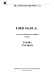
Getting To Know Your VM-54 Amplifier
The KRAMER VM-54 is a high quality, state-of-the-art, Video/Component Distribution
Amplifier designed for studio and other demanding applications. The VM-54 has three
looping input channels each with 18 outputs. With this configuration a 1:18 RGB
distributor can be formed. Each channel is subdivided into four groups of five or three
outputs, which may be tuned separately for gain and cable EQ. The three input channels
may be looped-through together to form a 1:54 DA, or other configurations (e.g. 1:18
Composite or 1:18 YC - using two channels). To form a 1:54 distributor, the channel 1
LOOP connector should be connected to the input connector of channel 2. The channel 2
LOOP connector should be connected to the input connector of channel 3. The termination
switches of channels 1 and 2 should be set at "Hi-z" and the channel 3 termination switch
should be set to "75 ". Output signals may be AC or DC coupled via front panel controls.
Signal bandwidth exceeding 350 MHz makes the VM-54 the first choice for a large
video/component distribution center.
Front/rear panel features of the VM-54 are described Figure 7, Table 10 and Table 11.
Figure 7: VM-54 Front/Rear Panel Features
Table 10: VM-54 Front Panel Features
No.
Feature
Function
1.
Power Switch
Illuminated switch: Supplies power to the unit.
2.
EQ trimmers (OUTPUTS 16-18,
Channels 1-3)
Controls cable equalization of video outputs 16-18 in
Channels 1-3.
3.
GAIN trimmers (OUTPUTS 16-18,
Channels 1-3)
Controls video levels of outputs 16-18 in Channels 1-3.
4.
EQ trimmers (OUTPUTS 11-15,
Channels 1-3)
Controls cable equalization of video outputs 11-15 in
Channels 1-3.
GAIN trimmers (OUTPUTS 11-15,
Channels 1-3)
Controls video levels of outputs 11-15 in Channels 1-3.
EQ trimmers (OUTPUTS 6-10,
Channels 1-3)
Controls cable equalization of video outputs 6-10 in
Channels 1-3.
5.
KRAMER ELECTRONICS LTD.
12
No.
Feature
Function
6.
GAIN trimmers (OUTPUTS 6-10,
Channels 1-3)
Controls video levels of outputs 6-10 in Channels 1-3.
7.
EQ trimmers (OUTPUTS 1-5,
Channels 1-3)
Controls cable equalization of video outputs 1-5 in
Channels 1-3.
8.
GAIN trimmers (OUTPUTS 1-5,
Channels 1-3)
Controls video levels of outputs 1-5 in Channels 1-3.
9.
AC/DC switches (Channels 1-3)
Selects AC/DC coupling for Channels 1-3 (DC coupling
when pressed).
10.
Hi-Z/75
Selects “ Hi-Z/75 ” impedance for Channels 1-3 (75
termination is applied when pressed).
switches(Channels 1-3)
Table 11: VM-54 Rear Panel Features
No.
Feature
Function
1.
INPUT BNC connectors (channels 1-3)
Video input (channels 1-3).
2.
LOOP BNC connectors (channels 1-3)
Provides video looping capability to increase
number of outputs (channels 1-3).
3.
OUTPUTS BNC connectors 1-18
(channels 1-3)
Video outputs that are identical to each other and to
the input.
4.
Power Connector
A 3-prong AC connector allows power to be supplied
to the unit. Directly underneath this connector, a fuse
holder houses the appropriate fuse.
KRAMER ELECTRONICS LTD.
13
INSTALLATION
Rack Mounting
KRAMER ELECTRONICS LTD.
14
CONNECTING TO VIDEO DEVICES
Video sources and output devices (such as monitors, projectors or recorders) may be
connected to the amplifiers through the BNC type connectors located on the back of the
units. Unused inputs are terminated to 75 , and active inputs should be terminated at the
connecting source. Please keep in mind that the output signal format will match that of the
input signal format. (Example: If input is composite, then output is composite.) All signal
connections that use more than one cable interconnecting between devices should be of
equal length. (Example: R,G,B cables between a camera and the amplifier should be equal
in length.) The signals supported by the various models are described in Table 12.
Table 1 : Signals Supported By Model
No.
Model
Supported signal
1.
VM-1010
Composite/component/YC/analog sync video
2.
VM-1015
Composite/component/ analog sync video
3.
VM-1021
Composite/component/ analog sync video
4.
VM-1042
Composite/RGBs/component
5.
VM-1044
Composite/RGBs/component
6.
VM-1055
Composite/RGBHsVs/ analog or TTL sync component
7.
VM-54
Composite/component RGBs video
USING THE VIDEO AMPLIFIERS
Powering On The Amplifier
1.
2.
NOTES
The amplifier should only be powered on, after all connections are
completed, and all source devices have been powered on. Do not
attempt to connect or disconnect any video, audio or control
signals to the amplifier while it is powered on!
The socket-outlet should be near the equipment and should be
easily accessible. To fully disconnect equipment, remove power
cord from its socket.
1) Press the toggle switch on the far-left front panel to the up position. In the up position, the
toggle switch glows red, and the active input button illuminates, as well.
2) Operate the acceptors.
Looping
The looping function enables the operator to extend the number of outputs per input. The
following example describes looping performed by using three amplifiers with one input
and five outputs each: A video signal reaches input of amplifier No. 1. From looping
connector of amplifier No. 1 a cable is connected to input socket of amplifier No. 2. The
loop output of amplifier No. 2 is connected to the input socket of amplifier No. 3. By this
way the input signal is divided into 15 separate output signals. The operator must always
switch to "Hi-z" the termination switch of all the amplifiers but the last. The last
amplifier’ s termination switch should always be at "75 " to maintain well-matched video
KRAMER ELECTRONICS LTD.
15
line (of 75 impedance) from first to last amplifier. Note that if looping function is not
used, the termination switch should be set to "75 ".
Level Control
(VM-1010, VM-1015, VM-1021, VM-54 only)
Level Control function enables the operator to control video signal level or compensate for
distortions such as those caused by cables that are too long. Using a non-standard, or an
uncalibrated video source also affects the incoming signal. Picture darkness is usually
caused by low video signal and on the other hand, excessive video level "burns" the
picture. The sync signal (approx. -0.3v) may be used to check conformity of the whole
video signal: If sync level is too low or too high, the incoming video signal is not within
the standard level. To correct the incoming video signal, an oscilloscope should be
connected to amplifier’ s output and the LEVEL trimmer adjusted until satisfactory sync
level and hence proper picture are achieved.
WARNING!
1.
Be aware that the amplifier was pre-calibrated for
transparent operation at the factory and re-tuning
it will upset signal transparency.
2.
Do not attempt to adjust the LEVEL trimmers
without using accompanying standard calibrated
oscilloscope or waveform monitor!
Equalization Control
(VM-1010, VM-1015, VM-1021, VM-54 only)
Equalization Control function enables the operator to compensate for degradation of the
video signal due to too long or non-standard cables. Popular cables such as the RG-59,
RG-11 or the RG-179 signal cause degradation/attenuation of the following values:
CABLE TYPE
LENGTH
FREQUENCY
ATTENUATION
RG-59
100 meter
100 meter
100 meter
100 meter
100 meter
100 meter
10MHz
100MHz
10MHz
100MHz
10MHz
100MHz
3.6dB
11dB
2.2dB
7.5dB
8dB
30dB
RG-11
RG-179
Degradation and loss of video signal are mainly caused due to stray capacitance which
occur in long cables. As longer cables or higher frequency are used, the problem becomes
worse, resulting in fine detail loss as well as color degradation. When RGB signals are
involved (200-300MHz), degradation is even greater, leading to a total loss of sharpness at
high resolution. It is necessary to compensate for the problem by using the amplifier’ s EQ.
Control trimmer. Equalization is performed as follows: A Color Bar Generator is
connected to amplifier’ s input and a Waveform Monitor (or an Oscilloscope with 75
termination) is connected to the long cable output. A known color bar signal is applied to
the amplifier’ s input and compared to the signal monitored at the far side. The operator
adjusts the EQ. trimmer until the measured output chrominance signal matches that of the
input signal.
KRAMER ELECTRONICS LTD.
16
WARNING!
1.
The amplifier was calibrated at the factory for
transparent operation at 1 meter. Any re-tuning will
upset amplifier’s transparency.
2.
Do not attempt to adjust the Equalization trimmers
without using accompanying standard calibrated
oscilloscope or waveform monitor!
Coupling
The coupling function enables the operator to determine whether the incoming video signal
is DC or AC coupled. When DC coupling is selected and proper standard video signal is
applied to the amplifier’ s input, the output signal is equal to the input signal. When AC
coupling is selected, DC components of the incoming signal are removed. DC coupling is
always preferable since AC coupling might cause some linearity distortions in low and
high frequencies (due to non-ideal behavior of capacitors). A problem may arise when the
incoming signal is riding on a DC offset especially when the acceptors are highly effected
by deviation of DC offsets (A/D converters for example), which in turn results in a
distorted picture.
Black Level Clamping
(VM-1015, VM-1021 only)
In the Black Level Clamping process, the incoming black level signal is "clamped" to
"zero". Whenever this process is activated (by pressing the "BLACK" pushbutton), the
amplifier’ s internal system automatically switches to AC coupling, thus removing the
original DC components of the incoming signal. The black level is clamped to "zero", thus
converting the input signal to a standard video signal. Whenever the picture is distorted,
too dark or too bright the DC offset is probably responsible so it is recommended to choose
AC coupling. If the malfunction still exists, the "BLACK" pushbutton should be activated
to restore the standard DC level of the video signal.
Sync Tip Clamping
(VM-1015, VM-1021 only)
Sync Tip Clamping is recommended for video signals such as RGB. The RGB signal
maximum amplitude is between 0.7V DC to 1V DC and their bottom level should be
always clamped to "zero". It sometimes contains sync signal ("sync on green") and
sometimes does not. When the Sync Tip Clamping process is activated (by pressing the
"Sync Tip" pushbutton), signal bottom level is clamped to "zero" and the whole video
signal is now positive and "zero" clamped.
TAKING CARE OF YOUR VIDEO AMPLIFIER
Do not locate your amplifier in an environment where it is susceptible to dust or moisture.
These may damage the electronics, and cause erratic operation or failure. Do not locate
your amplifier where temperature and humidity may be excessive. Do not clean your
amplifier with abrasives or strong cleaners. Doing so may remove or damage the finish, or
may allow moisture to build up. Take care not to allow dust or particles to build up inside
unused or open connectors.
KRAMER ELECTRONICS LTD.
17
TROUBLESHOOTING
NOTES
1. Please note that if the output signal is disturbed or
interrupted by very strong external electromagnetic
interference, it should return and stabilize when such
interference ends. If not, turn the power switch off and on
again to reset the machine.
2. If the recommended actions still do not result in satisfactory
operation, please consult your KRAMER Dealer.
Power and Indicators
Problem
Remedy
No Power
1.
Confirm that rocker switch is in “ON” position, and red LED is
illuminated.
2.
Confirm that power connections are secured at the amplifier and at the
receptacle. Make sure the receptacle is active, outputting the proper
mains voltage.
3.
If there is still no power, check the fuse. Remove power cord from the
AC outlet and from the machine and then, using a flat head screwdriver,
remove the fuse holder located directly below the power connector.
Confirm that the fuse is good by looking at the wire connected to the
ends of the fuse. If the wire is broken, replace the fuse with another,
with the same value.
Video Signal
Problem
Remedy
No video at the
output device,
regardless of
input selected.
1.
Confirm that your sources and output device are powered on and
connected properly. Video signals at the input of your amplifier should
be of an identical signal format at the output of your source. Video
signals at the output of your amplifier should be of an identical signal
format as at the input of your display or recorder.
2.
Confirm that any other amplifiers in the signal path have the proper input
and/or output selected.
3.
Use a Video Tester to test the video path leading to/from your amplifier.
1.
The amplifiers in this manual (except for the VM-1044 and VM-54)
have termination switches on each input. Verify that the video line is
well matched through 75 impedance, otherwise it results in a video
level that is too high or too dim when looping is performed and the
termination switches are not in proper position.
2.
Confirm that the connecting cables are of high quality, properly built and
terminated with 75 BNC connectors. Check level controls located on your
source input device or output display or recorder.
Video level is too
high or too dim.
KRAMER ELECTRONICS LTD.
18
Problem
Remedy
Noise bars "roll"
up or down in the
output image
Hum bars (ground loop) are caused by a difference in the ground potential of any
two or more devices connected to your signal path. This voltage difference passes
through any available interconnection, including your video cables.
or:
WARNING!
Low frequency
hum in the output
signal
Do not disconnect the ground from any piece of video
equipment in your signal path!
Check the following to remove hum bars:
1.
Confirm that all interconnected equipment is connected to the same
phase of power, if possible.
2.
Remove equipment connected to the phase that may be introducing
noise, such as motors, generators, etc.
3.
Disconnect all cables and reconnect them one at a time until ground loop
reappears. Disconnect the affected cable and replace, or insert an
isolation device (opto isolator or transformer) in the signal path.
KRAMER ELECTRONICS LTD.
19
For the latest information on our products and a list of
Kramer distributors, visit our Web site:
www.kramerelectronics.com
where updates to this user manual may be found.
We welcome your questions, comments and feedback.
Kramer Electronics, Ltd.
Web site: www.kramerelectronics.com
E-mail: [email protected]
P/N: 2900-001001 REV 4