1
IPS-AM
ORDERCODE D6503
Congratulations!
You have bought a great, innovative product from DAP Audio.
The DAP Audio IPS-AM brings excitement to any venue. Whether you want simple plug-&-play action or a
sophisticated show, this product provides the effect you need.
You can rely on DAP Audio, for more excellent audio products.
We design and manufacture professional audio equipment for the entertainment industry.
New products are being launched regularly. We work hard to keep you, our customer, satisfied.
You can get some of the best quality, best priced products on the market from DAP Audio.
So next time, turn to DAP Audio for more great audio equipment.
Always get the best -- with DAP Audio!
Thank you!
DAP Audio
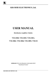
DAP Audio IPT-AM Guide
Warning..…...................................................................................………………………………………….
Safety-instructions………………….……………………………………………………………….…
Operating Determinations…………………………………………………………………………...
Connecting to the mains…………………………………………………………………………….
2
2
4
4
Description..…..............................................................................……….…………………………………
Features…………………………..……………………………………………….………………….….
Overview Front panel..…………..………………………………………………………………....…
Overview Back panel..………….……………………………………………………………….……
5
5
6
7
Operation....................................................................……………………………..………………………..
Connecting the device……………………………………………………………………………….
Link……………….………………………………………………………………………………………..
Using the active up/down switches………………………………………………………………..
Serial linking.…………………………………………………………………………………………..…
Audio connecting………………………………………………………………………………………
9
9
10
11
11
12
Maintenance………..............................….......................................………..………….…….………….… 12
Troubleshooting………..............................…................................………..………….…….………….….. 12
Product Specifications.................................................................……………….…….…………………... 13
1
WARNING
CAUTION!
Keep this system away from rain and moisture!
FOR YOUR OWN SAFETY, PLEASE READ THIS USER MANUAL CAREFULLY
BEFORE YOUR INITIAL START-UP!
SAFETY INSTRUCTIONS
Every person involved with the installation, operation and maintenance of this system have to:
be qualified
follow the instructions of this manual
CAUTION! Be careful with your operations.
With a dangerous voltage you can suffer
a dangerous electric shock when touching the wires!
Before you initial start-up, please make sure that there is no damage caused by transportation. Should there
be any, consult your dealer and do not use the system.
To maintain perfect condition and to ensure a safe operation, it is absolutely necessary for the user to follow
the safety instructions and warning notes written in this manual.
Please consider that damages caused by manual modifications to the system are not subject to warranty.
This system contains no user-serviceable parts. Refer servicing to qualified technicians only.
IMPORTANT:
The manufacturer will not accept liability for any resulting damages caused by the non-observance
of this manual or any unauthorized modification to the system.
Never let the power-cord come into contact with other cables! Handle the power-cord and all
connections with the mains with particular caution!
Never remove warning or informative labels from the unit.
Never use anything to cover the ground contact.
Do not insert objects into air vents.
Do not connect this system to a dimmer pack.
Do not switch the system on and off in short intervals, as this would reduce the system’s life.
Do not open the device and do not modify the device.
Do not open this device. Risk: hazardous radiation exposure.
Only use system indoor, avoid contact with water or other liquids.
Avoid flames and do not put close to flammable liquids or gases.
Always disconnect power from the mains, when system is not used. Only handle the power-cord by
the plug. Never pull out the plug by tugging the power-cord.
Make sure you don’t use the wrong kind of cables or defective cables.
Make sure that the signals into the mixer are balanced, otherwise hum could be created.
Make sure you use DI boxes to balance unbalanced signals; all incoming signals should be clear.
Make sure that the available voltage is not higher than stated on the rear panel.
2
Make sure that the power-cord is never crimped or damaged. Check the system and the powercord from time to time.
Make sure that the amplifier is turned down, before turning the power on or off. So you can avoid
supersonic frequencies, which could damage your speakers.
Don't put your equipment next to TV, radio, etc., because of interference or distortion.
If you connect other parts of the system, be careful of ground loops.
The best way to avoid ground loops is connecting the electrical system ground to one central point
("star" system). In this case the mixer can act as a central point.
Before changing the ground, always turn off your amplifier.
Please read this manual carefully and keep it for future reference. Remember that the amplifier has a
better value on the market, if you save the carton and all packing materials.
Always operate the unit with the AC ground wire connected to the electrical system ground.
Connecting amplifier outputs to oscilloscopes or other test equipment, while the amplifier is in
bridged mode, may damage both the amplifier and test equipment.
Do not drive the inputs with a signal level bigger, than required to drive the equipment to full output.
In system setup, the amplifier's output power must be 50%-100% more than the loaded loudspeakers
rated power.
Please turn off the power switch, when changing the power cord or signal cable, or select the input
mode switch.
In typical use, please set the volume at 0dB position.
Sometimes, when you want to send one signal to more than one amplifier, you should use a signal
distributor.
If your Dap Audio device fails to work properly, discontinue use immediately. Pack the unit securely
(preferably in the original packing material), and return it to your Dap Audio dealer for service.
Allow time to cool down, before cleaning or servicing.
For replacement use fuses of same type and rating only.
Prevent distortion! Make sure that all components connected to the DSA have sufficient power
ratings. Otherwise distortion will be generated because the components are operated at their limits.
Avoid ground loops! Always be sure to connect the power amps and the mixing console to the same
electrical circuit to ensure the same phase!
If system is dropped or struck, disconnect mains power supply immediately. Have a qualified
engineer inspect for safety before operating.
If the system has been exposed to drastic temperature fluctuation (e.g. after transportation), do not
switch it on immediately. The arising condensation water might damage your system. Leave the
system switched off until it has reached room temperature.
This device falls under protection class I. Therefore it is essential to connect the yellow/green
conductor to earth.
Repairs, servicing and electric connection must be carried out by a qualified technician.
WARRANTY: Till one year after date of purchase.
3
OPERATING DETERMINATIONS
If this system is operated in any other way, than the one described in this manual, the product may suffer
damages and the warranty becomes void. Any other operation may lead to dangers like short-circuit,
burns, electric shock, etc. You endanger your own safety and the safety of others!
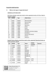
Connection with the mains
Connect the device to the mains with the power-plug.
Always pay attention, that the right color cable is connected to the right place.
International
EU Cable
UK Cable
US Cable
Pin
L
BROWN
RED
YELLOW/COPPER
FASE
N
BLUE
BLACK
SILVER
NUL
YELLOW/GREEN
GREEN
GREEN
EARTH
Make sure that the device is always connected properly to the earth!
Improper installation can cause serious damage to people and property!
4
Description of the device
Features
Intelligent fire alarm interface
Auto activating function
Minicomputer intelligent interface
Up to neighbor +/-4 zones can be activated by inputting alarm signal
Controllable 30 channels each set. Up to 120 channels can be controlled by using multiple units.
5
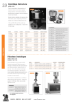
Front panel
1. AC Power Switch.
This is the main Power switch. Press to turn the amplifier on.
2. Link Status Display.
When operating the unit stand alone, the HOST LED lights up. If the unit is linked with other IPS-AM’s the
LED’s will indicate following:
HOST, controls CH1-CH30.
SLAVE1, controls CH31-CH60.
SLAVE2, controls CH61-CH90.
SLAVE3, controls CH91-CH120.
E.g. SLAVE 3 LED and CH12 LED light both up. This indicates that alarm CH102 is active.
3. Alarm Status Display.
Turn on the power switch, alarm LEDs 1-30 light up green, which means the unit is in
standby status. When receiving an alarm signal on the alarm in, the corresponding channel's LED will
light up red.
4. All Alarm LED.
The LED will light up when a general alarm is active. A general alarm can only be activated or
deactivated by the all alarm switch.
5. All Alarm Button.
If the ALL ALARM BUTTON is pressed, all channels will go into alarm. Pressing the ALL ALARM Button
again will erase the general alarm.
6. AC LED
Indicates that AC power is connected and the device is turned on. The LED will dim if the mains
power fails.
7. DC LED.
Indicates that an external 24Vdc power supply is present.
6
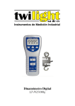
Back panel
8. AC Inlet.
This connector is meant for the connection of the supplied main cord. Connect one end of the power
cord to the connector, the other end to the mains, then turn on the power switch (1) to operate
the unit.
Note: Please make sure that the supply voltage matches the operation voltage before connecting
the unit to mains.
9. Fuse Holder
10. GND Screw.
This screw offers a separate ground connection. Can be useful in case of grounding problems.
11. DC 24V Input.
Used to connect an external back up power supply of 24Vdc (e.g. Battery)
12. Activate UP Switch.
This switch is used to link up to 4 neighbor Channels Up the incoming alarm channel. For more details
and example settings see also “Using the up/down switches” on Page 10/11.
13. Alarm In Socket
All incoming alarm signals have to be connected to the 37-pin socket.
Pin 1-30 are input terminals for alarm channel 1-30.
Pin 31-37 are com.
Depending on the position of the input logic level switch, the unit will recognize an alarm signal as either
a logic “1” (high) or as a logic “0” (low) signal. A logical “1” signal should range between +5V and +24V.
Input current draw is less than 3mA.
14. Activate DOWN Switch.
This switch is used to link up to 4 neighbor Channels Down the incoming alarm channel. For more details
and example settings see also “Using the up/down switches” on Page 10/11.
15. Input Logic Level Switch.
High-level signals are valid when the switch is set to HIGH position. In LOW position, the low-level signals
are valid.
16. Link Up Socket.
This socket can be used if 30 alarm channels are not sufficient. Using the LINK UP and LINK DOWN sockets
you can LINK several IPS-AM units. See also “Linking More Units” on page 10.
7
17. Link Down Socket.
This socket can be used if 30 alarm channels are not sufficient. Using the LINK UP and LINK DOWN sockets
you can LINK several IPS-AM units to expand your channels. See also Chapter “Linking More Units” on
page 10.
18. Or Gate Out Socket.
As soon as any channel receives an alarm signal, the OR GATE OUT socket will be activated. Via the
socket, you can output the alarm signal to activate for example an emergency alarm generator.
19. Alarm Output Socket.
The 25-pin sockets are used to output the alarm signals.
Pin 1-10 are live terminals, indicated by LED 1-10.
Pin 14-23 are com.
Pin 11-13 and pin 24-25 are not connected.
The alarm output sockets will be activated if an alarm is active.
20. Alarm Output Socket.
The 25-pin sockets are used to output the alarm signals.
Pin 1-10 are live terminals, indicated by LED 11-20.
Pin 14-23 are com.
Pin 11-13 and pin 24-25 are not connected.
The alarm output sockets will be activated if an alarm is active.
21. Alarm Output Socket.
The 25-pin sockets are used to output the alarm signals.
Pin 1-10 are live terminals, indicated by LED 21-30.
Pin 14-23 are com.
Pin 11-13 and pin 24-25 are not connected.
The alarm output sockets will be activated if an alarm is active.
8
Operation
Installation
Remove all packing materials from the IPS-WPT. Check that all foam and plastic padding is removed.
Secure the equipment into a 19" rack. Connect all cables.
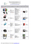
Connecting the device
Below an example of a possible setup.
NOTE: Always turn off and disconnect the amplifier from mains voltage before making any connections.
9
Linking More Units.
Your Alarm Matrix provides 30 preset alarm channels Linking up more devices allows you to control more
than 30 alarm channels, if several units are linked, only the “OR GATE OUT” of the HOST is valid.
Using The Active Up/ Active Down Dipswitches
Using the active up/ active down DIP switches allows you to link up to +/-4 neighbor zones to an alarm
channel.
1.
2.
3.
4.
Activate up: n+1; Activate down: n-1
Activate up: n+2; Activate down: n-2
Activate up: n+3; Activate down: n-3
Activate up: n+4; Activate down: n-4
n = the incoming alarm.
10
Example 1: We want to Link 2 alarms up to each incoming alarm. The DIP switches should be set according
the following diagram.
In case of alarm on channel 14 an alarm will also be sent to channels 15 and 16. The according LED’s on the
front panel will also light up red.
Example 2: We want to Link 3 alarms up and 4 alarms down to each incoming alarm. The DIP switches should
be set according the following diagram.
In case of alarm on channel 14 an alarm will also be sent to channels 11, 12, 13, 15, 16, 17 and 18. The
according LED’s on the front panel will also light up red.
Serial Linking
If you need to link up more than +/- 4 zones you need a second device. In the example given below, The
system is set up for linking 6 channels up and 3 channels down.
11
Audio connection
Use the 6.3mm cable to connect the OR GATE OUT to REMOTE IN of an emergency alarm generator. As soon
as the Alarm Matrix receives an alarm signal, the OR GATE OUT will send an alarm signal to activate the
emergency alarm for alarming. OR GATE OUT REMOTE IN Alarm Matrix Emergency Alarm
Maintenance
The DAP Audio IPS-AM requires almost no maintenance. However, you should keep the unit clean.
Disconnect the mains power supply, and then wipe the cover with a damp cloth. Do not immerse in liquid.
Do not use alcohol or solvents.
Keep connections clean. Disconnect electric power, and then wipe the DMX and audio connections with a
damp cloth. Make sure connections are thoroughly dry before linking equipment or supplying electric
power.
Replacing a Fuse
Power surges, short-circuit or inappropriate electrical power supply may cause a fuse to burn out. If the fuse
burns out, the product will not function whatsoever. If this happens, follow the directions below to do so.
1. Unplug the unit from electric power source.
2. Insert a screwdriver into the slot in the fuse cover. Open the fuse holder.
3. Remove the broken fuse. If brown or unclear, it is burned out.
4. Insert the replacement fuse into the holder where the old fuse was. Reinsert the fuse cover.
Be sure to use a fuse of the same type and specification. See the product specification label for details.
Troubleshooting
DAP Audio IPS-AM
This troubleshooting guide is meant to help solve simple problems. If a problem occurs, carry out the steps
below in sequence until a solution is found. Once the unit operates properly, do not carry out following steps.
1. If the device does not operate properly, unplug the device.
2. Check the fuse, power from the wall, all cables, etc.
3. If all of the above appears to be O.K., plug the unit in again.
4. If you are unable to determine the cause of the problem, do not open the amplifier, as this may damage
the unit and the warranty will become void.
5. Return the amplifier to your Dap Audio dealer.
12
Product Specifications
Model
Power supply
Alarm Input Channel
Power consumption
Alarm Output Channel
Input Logic Level
Alarm Output Level
Link
Weight
Dimension (LxWxD)
Alarm Matrix
AC 110-120/220-240V 50/60Hz
30ch
Less then 18W
30ch
+5 - 24V High Level Signal or 0V selectable
0V (Short)
Up, Down +/- 4 Channel Extension
6.73kg (14.84lb)
483mm x 370mm x 88mm (19.02"x 14,57" x 3.46")
Design and product specifications are subject to change without prior notice.
13
2007 Dap Audio.