1
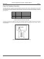
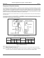
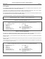
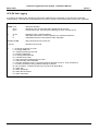
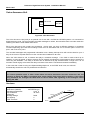
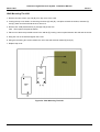
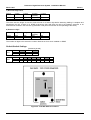
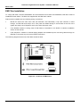
Panasonic Digital Business System - Installation Manual
March 1997
Issue 5
Panasonic
Digital Business System
Installation Manual
1
Panasonic Digital Business System - Installation Manual
March 1997
Issue 5
Contents
INTRODUCTION
5
INSTALLATION OF THE CENTRAL CONTROL UNIT (CCU)
6
REMOVING THE COVERS
WALL MOUNTING THE CCU
CONNECTION OF THE MAINS LEAD
6
7
8
INSTALLING THE BUILT IN BACKUP BATTERIES
9
INSTALLATION OF THE MODULAR CARDS
10
LINKING TWO CCUS
12
CONNECTION OF EXCHANGE LINES AND EXTENSIONS
13
ATTACHING A DDK CONNECTOR
PIGGY-BACK CONNECTIONS
EXCHANGE LINE / PBX EXTENSION WIRING
EXTENSION CONNECTION
DSS CONSOLE CONNECTION
13
14
14
15
16
WALL MOUNTING THE PROPRIETARY EXTENSION TELEPHONES
THE VB3411, VB3411D, VB3411LDS, VB3611D AND VB3611DS
WALL MOUNTING THE VB3011
17
17
17
SLT RING GENERATOR
18
POWER FAIL TELEPHONE CONNECTION
19
DOORPHONE & DOORLATCH INTERFACE
20
MUSIC ON HOLD
21
2
Panasonic Digital Business System - Installation Manual
March 1997
Issue 5
EXTERNAL PAGING ADAPTER AND LOUD RINGING BELL
22
RS232C INTERFACE
23
ON SITE PC PROGRAMMING
CALL LOGGING
CPC-EX CALL LOGGING
23
24
26
REMOTE PROGRAMMING INTERFACE
29
METER PULSE DETECTION CARDS
30
EXTERNAL BATTERY
31
HEADSET CONNECTION
32
HOST WORKING
32
E&M CARD
33
NETWORK MATCHING AND GAIN CONTROL SWITCHES
TYPICAL EXAMPLES
WIRING
AC15A CARD
34
35
36
38
TYPICAL EXAMPLES
WIRING
39
40
PRIMARY RATE ISDN INTERFACE
41
DASS II IMPORTANT INFORMATION
E-ISDN IMPORTANT INFORMATION
MAJOR EQUIPMENT FAILURE
INSTALLATION
INSTALLING THE ISDN TRK CARD
CONNECTION OF A SECOND ISDN CARD TO DOUBLE CCU DBS SYSTEMS
INSTALLING THE DASS II MDF
INSTALLING THE E-ISDN MDF
INSTALLING THE SYNCHRONISATION UNIT
3
41
41
41
41
43
43
44
44
50
Panasonic Digital Business System - Installation Manual
March 1997
Issue 5
COMMON PROBLEMS AND THEIR SOLUTIONS
51
VOICE ANNOUNCE UNIT
52
HARDWARE
WALL MOUNTING THE VAU
WIRING AND CABLE CONNECTIONS
VAU DIP-SWITCH SETTINGS
DEFAULT SWITCH SETTINGS
OPERATIONAL CONSIDERATIONS
52
53
54
55
56
57
EMI FILTER INSTALLATION
58
4
Panasonic Digital Business System - Installation Manual
March 1997
Issue 5
Introduction
This section describes the installation and connection of the Digital Business System and its components.
Read the following section before beginning installation work.
Important
This apparatus must be installed in accordance with BS6701 and general approval NS/G/23/L/100005. This is a
condition of the approval. Any installation which does not comply with this condition will invalidate the approval of
that particular installation.
This equipment requires a maintenance contract issued by a maintainer holding BSI approval. This is a statutory
requirement.
This is a class A product.
In a domestic environment this product may cause radio interference, in which case the user may be required to
take appropriate measures.
This product has been CE marked to show compliance with the EMC Directive 89/336/EEC amended by
92./31/EEC and 93/68/EEC.
5
Panasonic Digital Business System - Installation Manual
March 1997
Issue 5
Installation Of The Central Control Unit (CCU)
Note
1
Do not use the telephone system components near sources of electric ‘noise’ or interference. Examples
are: fluorescent lamps, air conditioners, televisions, fridges, washing machines, and radios.
2
The equipment should not be exposed to heat sources, direct sunlight, extreme temperature, moisture or
damp, strong vibrations, greasy or dusty environments.
Operating temperature 0ºC - 40ºC
Operating humidity
0% - 60%
Do not install the equipment in damp or humid environments such as bathrooms and swimming pools.
3
Never attempt to insert wires, pins or similar objects in the vents or openings of the equipment.
4
Never clean the equipment with benzene, paint thinner or other solvent materials. Wipe with a soft cloth to
clean.
5
Do not change the installation location without consulting your dealer/maintainer.
6
Installation of the equipment near welding machines or broadcast antennae may cause interference.
Removing The Covers
Figure 1 - Cover Securing Screw Locations
1
Remove the 8 screws securing the front and side covers.
2
Remove the front cover by lifting it forward and up from the CCU.
3
Remove the side panels by sliding the upwards and lifting them away from the side of the CCU
6
Panasonic Digital Business System - Installation Manual
March 1997
Issue 5
Wall Mounting The CCU
1
Using the dimensions given for the appropriate CCU size in the table below fix four mounting screws into
the wall leaving a 7mm protrusion to accept the mounting plate. Ensure the fixing method is appropriate to
the type of wall.
2
Fix the four mounting plates provided to the rear of the CCU using 2 screws per plate.
3
Lift the CCU and use the holes in the mounting plates to hang it on the screws mounted in the wall.
4
Tighten the screws to secure the CCU.
Figure 2 - Wall Mounting The CCU
DBS 38
DBS 68
DBS 90
A
335 mm
445 mm
445 mm
B
570 mm
570 mm
570 mm
Table 1 - Mounting Point Dimensions
7
Panasonic Digital Business System - Installation Manual
March 1997
Issue 5
Connection Of The Mains Lead
The DBS must be connected to the mains via a fused spur with a double pole isolation switch provided at the spur
output or close to the equipment.
The wires in the mains lead correspond to the following code:
Wire Colour
Meaning / Terminal
Blue
Brown
Green / Yellow
Neutral
Live
Earth
Possible Alternative Terminal
Markings
N or coloured black
L or coloured red
E or safety earth symbol
or coloured green
or coloured green and yellow
Table 2 - Wiring Colour Codes
If in doubt consult a qualified electrician.
Figure 3 - Connection Of Mains Lead
8
Panasonic Digital Business System - Installation Manual
March 1997
Issue 5
Installing The Built In Backup Batteries
There are two types of internal battery. One type for the DBS 38 and another for the DBS 68 and DBS 90. Use the
set appropriate to the CCU being installed.
1
Link the batteries together as shown below.
2
Connect the red and blue leads to the + and - terminals respectively of the end batteries.
3
Insert the batteries into the bay in the CCU.
Figure 4 - Battery Wiring & Location DBS 38, DBS 68 & DBS 90
Model Number
VB2450A2UK
For CCU
DBS 38
VB26502UK
DBS 68 / 90
Specification
Sealed lead acid battery
2 x BT2007 (P) 12v 6.5Ah
Sealed lead acid battery
4 x BT2005 (P) 6v 8.5Ah
Table 3 - Internal Battery Specifications
Note 1: The batteries can maintain system operation for approximately 30 minutes for a DBS 38 or DBS 68 or 15
minutes for DBS 90. The duration of system operation on battery power is dependant upon the traffic
conditions at the time.
Note 2: Panasonic recommend replacement of the backup batteries every three yeas.
Note 3: The parts listed in table 3 are recommended. However any batteries which meet the specification can be
substituted.
9
Panasonic Digital Business System - Installation Manual
March 1997
Issue 5
Installation Of The Modular Cards
The DBS is configured using modular cards to support exchange lines, digital extensions, analogue extensions
and system control functions. These cards are installed in the CCU in designated slots. The numbers of slots and
hence the numbers of cards each CCU can support varies with the CCU used. The table below shows how many
of each card can be installed in each CCU.
Larger DBSs are created by linking a DBS 90 CCU to a second DBS CCU cabinet. the link is via the link cable
cards and cable (VB3691UK). The CCU which contains the CPC card and SCC card is the Master CCU and the
second CCU is the Slave CCU. When CCUs are linked in this way the AUX1 slot in the Master and SCC slot in the
Slave are not used.
Each CCU has one universal slot marked EXT/LINE which is capable of supporting all extension and trunk card
types. In a double CCU system there are two EXT/LINE slots, one in each CCU.
To install a card:
1
Turn off the system power and remove the front cover.
2
Hold the card to be installed with the connection strip facing the backplane of the CCU and the name label
at the top. Check that the card can be installed in the required slot.
3
Locate the guides at the top and bottom of the card into the guide slots in the CCU and gently push the
card into the CCU. When it reaches the connection strip on the backplane a slightly heavier push will
engage the connectors and the card front twill be flush with the front edge of the slot.
4
Rewire system MDF if required.
5
Switch On The System.
Repeat 2 & 3 for each card to be installed.
10
Panasonic Digital Business System - Installation Manual
March 1997
Issue 5
Slot
Card
Description
CPU
SCC
LINE
Central Processor
System Control
Line Card
E&M Card(Note 3)
Digital Extension Card
Analogue Ext. Card
Line Card
Extension Card
E&M Card(Note 3)
ISDN Card(Note 4)
DTMF Receiver
Link Cable
EXT
EXT
LINE
AUX
/
Number Of Slots In CCU
By System Size
Card Model
38
1
1
1
68
1
1
2
90
1
1
3
128
1
1
4
158
1
1
5
180
1
1
6
3
6
8
11
14
16
1
1
1
2
2
2
2
2
2
2
2
2
VB3775
VB3665A
VB3660
VB3663
VB3670
VB3680
VB3660
VB3670 / VB3680
VB3663
VB3664
VB3682
VB3691
Table 4 - Relation Between Slots And Modular Cards
Note 1: Never remove the cover of a modular card.
Note 2: To ease installation of multiple cards install then working from the left of the CCU to the right. LINE -DECAEC-SCC-CPC-MFR- Link card.
Note 3: A maximum of 2 E&M cards can be fitted to any CCU. The DBS 38 CCU can take 1, the DBS 68 and 90
CCUs can take 2. Refer to the E&M card installation instructions for full details.
Note 4: A maximum of 1 ISDN card can be fitted to any system regardless of size. It must occupy a universal slot.
See ISDN card installation instructions for full details.
Important
The first extension card fitted to a system in slot EXT1
MUST be a digital extension card
11
Panasonic Digital Business System - Installation Manual
March 1997
Issue 5
Linking Two CCUs
CCUs are linked using the connection cables and cards VB3691. The master CCU must be a DBS 90. One CPU
card and one SCC are installed in the master CCU to provide control for the whole system. When two systems are
linked the SCC slot in the slave and AUX 1 slot in the master are not used.
1
Remove the covers from the CCUs. Install the link cards in the AUX 2 slots at the right hand side of the
CCUs. Ensure the master card is installed in the master CCU and the slave in the slave CCU.
2
Connect the wire provided on the slave card to the 24v pin of the 24v and GND terminal CN24 on the
slave CCU.
3
If two DTMF Receiver (MFR) cards are fitted to the system cut the jumper wire marked J3 on either of the
MFR cards. Failure to do this will cause the MFR cards to cancel out and DTMF dialling will not be
recognised by the system.
4
The first extension card of the master CCU must be a Digital extension card (DEC). The remaining
extension cards can be any combination of Analogue extension card (AEC) and DEC.
5
Ensure the switch SW1 on the master connection card is set to the factory default shown in table 5 below.
6
Connect the link cable to the cards through the access holes provided in the chassis of the CCUs.
7
Connect the flying leads from the master end of the connection cable to a frame ground on the master
CCU.
8
Allow for the reinstallation of the CCU covers and install the EMI filters as close as possible to the CCUs
at both master and slave ends.
1
OFF
2
ON
3
OFF
SW1 Switches
4
5
ON
OFF
6
OFF
7
OFF
Table 5 - SW1 Factory Presets
Figure 5 - Jumper And Switch Locations
12
8
OFF
Panasonic Digital Business System - Installation Manual
March 1997
Issue 5
Connection Of Exchange Lines And Extensions
To comply with EMC Directive 89/336/EEC and it amendments 92./31/EEC and 93/68/EEC, EMI filters must be
installed as per the EMI Filter Installation section later in this manual.
Connection of exchange line and extension wiring to the DBS is made via proprietary DDK connectors supplied
with the CCU. Additional connectors can be obtained as spare part items.
Each DDK can accommodate two exchange or extension connections.
The DBS can be directly wired to the Network Test an Termination Point (NTTP) via DDKs, however it is
recommended that an Intermediate Distribution frame (IDF) is installed and the exchange and extension wiring
jumpered across to the wiring running to the DBS.
Figure 6 - Recommended Connection Schematic
Attaching A DDK Connector
1
Open the DDK.
2
Insert the wires to connected into the four holes on the flap.
3
Ensure the wires do not slip out of the holes and close the DDK using a pair of pliers to press the two parts
firmly together. The blades in the second section of the DDK will cut through the insulation on the wire and
make contact with the conductor.
4
Plug the completed DDK into the appropriate port connection on the Master Distribution Frame (MDF) at
the top of the DBS CCU.
13
Panasonic Digital Business System - Installation Manual
March 1997
Issue 5
Piggy-Back Connections
The DBS can be used a host or subsidiary system. As a subsidiary system piggy-backed from the extension ports
of a host PBX the connection from the host is presented as a series of exchange lines to the DBS. The DBS is
then configured through programming to use those ports as piggy-backed lines and will provide recall signalling to
the host.
The DBS can be configured to provide earth or timed break recall signalling to the PBX. Timed break will operate
on the wiring from the PBX extensions. Earth recall will require the connection of an earth wire from the PBX earth
point to the PBX EARTH connection point on left hand end of the DBS MDF.
If an earth connection is required to the DBS this must also be carried across to the EXT/LINE slot wiring using a
DDK to DDK jumper wire so that any PBX extensions connected there can also send earth recall. The following
diagram shows the location of the connection points on the DBS CCUs.
Figure 7 - PBX Earth Connection Points
Exchange Line / PBX Extension Wiring
Use each DDK to connect two circuits as shown.
Figure 8 - Exchange Line / PBX Extension Connection
14
Panasonic Digital Business System - Installation Manual
March 1997
Issue 5
Extension Connection
Extension connections are made via DDK connectors in a similar way to those for the exchange lines. Both Digital
and Analogue extensions connect using two wires. The DSS operator console is wired as a digital extension or
piggy backed with the operator extension. Extension ports 1 and 2 are the ports for operator extensions DSS units
when installed will operate with one or other of these ports as per system programming.
Digital Extension Connection
Digital Extensions are wired to secondary sockets pins 3 and 4.
Figure 9 - Digital Extension Connection
15
Panasonic Digital Business System - Installation Manual
March 1997
Issue 5
Analogue Extension Connection
Analogue Extensions are wired to master sockets pins 2 and 5.
Figure 10 - Analogue Extension Connection
DSS Console Connection
DSS 1 for the operator extension on port 1 and DSS 1 for the operator extension on port 2 can be wired sharing
the same socket as the extension or wired as an individual digital extension. When the socket is shared use the
link wire supplied with the DSS to connect the operator extension to the DSS unit then connect only the cord from
the DSS unit to the socket.
The second DSS unit for each operator is wired as a digital extension.
DSS consoles can be connected to any vacant digital extension port supported by a digital extension card.
Figure 11 - DSS Console Connection
16
Panasonic Digital Business System - Installation Manual
March 1997
Issue 5
Wall Mounting The Proprietary Extension Telephones
The VB3411, VB3411D, VB3411LDS, VB3611D and VB3611DS
The VB3411, VB3411D, VB3411LDS, VB3611D and VB3611DS handsets have a base moulding which can be
unclipped rotated and reattached to provide wall a wall mounting bracket.
Figure 12 - Removal And Reattachment Of The Built In Wall Bracket
Wall Mounting The VB3011
The VB3011 has a built in wall mounting bracket which is removed and refitted by lifting the bracket and pressing
the two holding clips to release the bracket. Rotate the bracket and re-clip it onto the three clips provided at the
base of the handset. Remove the plastic section to free the screw hole.
Figure 13 - Wall Mounting The VB3011
17
Panasonic Digital Business System - Installation Manual
March 1997
Issue 5
SLT Ring Generator
The SLT Ring Generator is a power supply to provide ringing voltage for analogue extensions. It is sufficiently
powerful to ring 20 analogue extensions at any one time. One Ring Generator is required for every CCU. When
installing a double CCU system one Ring Generator must be fitted to each CCU in which analogue extensions are
connected and required to ring.
Figure 14 - Fitting The SLT Ring Generator
18
Panasonic Digital Business System - Installation Manual
March 1997
Issue 5
Power Fail Telephone Connection
The DBS CCUs have a number of power fail telephone connection points. When a power failure occurs the first
few exchange lines are switched to the Power Fail Units (PFUs). 40% of incoming only lines and 20% of incoming
and outgoing lines must be supported in power fail mode. The DBS CCUs each have the following numbers of
power fail lines.
System
DBS 38
DBS 68
DBS 90
DBS 128
DBS 158
DBS 180
No. Of PFUs
3
4
5
8
9
10
Lines Supported
1-3
1-4
1-5
1 - 5 CCU 1 / 1 - 3 CCU 2
1 - 5 CCU 1 / 1 - 4 CCU 2
1 - 5 CCU 1 / 1 - 5 CCU 2
Table 6 - Power Fail Connections Per CCU
Connection of the PFUs is via DDK in the same way as analogue extensions. The DDK connections are located at
the left hand end of the CCU above the exchange line connection points. The highest lines are on DDK 1 and they
work downwards.
Figure 15 - Power Fail Connection (DBS 90 Shown)
19
Panasonic Digital Business System - Installation Manual
March 1997
Issue 5
Doorphone & Doorlatch Interface
The doorphone and doorlatch interface is a separate unit which should be wall mounted externally to the DBS
CCU. It connects to one exchange line port which must be set for pulse dialling and the 24v and GND terminals
CN23. The doorphone unit supports two doorphones and has two doorlatch interfaces. Since it connects to a single
exchange line only one doorphone and latch can be used at one time. Should the second doorphone be used
whilst the first one is in use the extension talking the first doorphone hears an tone (Ping-Pong) and can either
press 2 to cut off the first call and answer the second or 3 to open the latch.
Doorphone calls which are not answered will be cut off after a pre determined time set by DIP switch settings in
the interface box.
The door latch is trigger is via relays OPENER 1 and OPENER 2. These are normally open relays which close for
a predetermined time set by DIP switches on the interface card. The relay is used as the switch in the latch circuit.
It can handle 1 amp at 30v DC or 50v AC maximum.
Figure 16 - Doorphone Interface Connections
Doorphone
Call Time
15 Sec *
30 Sec
60 Sec
DIP SW
3
ON or
OFF
OFF
OFF
Latch
Open Time
4
OFF
5
OFF
1 Sec
ON
OFF
OFF
ON
3 Sec
5 Sec *
DIP SW
6
ON or
OFF
OFF
OFF
7
OFF
8
OFF
ON
OFF
OFF
ON
* = Initial Setting
Table 7 - DIP Switch Settings
Note 1: Switch positions 1 and 2 have no function.
Note 2: CN23 is a 4 pin DDK connection. Pins 1 and 2 provide 24vDC and 3 and 4 provide a ground connection.
Therefore connect to 1 or 2 and 3 or 4.
Note 3: To comply with EMC directives EMI filters must be fitted as indicated to the Doorphone Interface
connections. Refer to the EMI Filter Installation section of this manual for filter installtion details.
20
Panasonic Digital Business System - Installation Manual
March 1997
Issue 5
Music On Hold
An external Music On Hold (MOH) source can be connected to JK1, an RCA phono jack on the right hand end of
the MDF. The single source can be used to provide MOH and Background Music (BGM) for the system. Once the
source has been connected the system programming requires setting and the DBS switched off and back on to
enable the function.
The input impedance is 10K ohms, -10 dB level maximum.
Important
This port does not provide isolation sufficient to satisfy the requirements of BS6301. Apparatus connected to this
port must be approved to BS6301 or have previously been evaluated against British Telecommunications PLC
Technical Guides 2 or 26 and given permission to attach. Other usage will invalidate any approval given to the
apparatus.
Figure 17 - Location Of The MOH Connector
21
Panasonic Digital Business System - Installation Manual
March 1997
Issue 5
External Paging Adapter And Loud Ringing Bell
The External Paging Adapter (EPA) VB30966 comes with a factory fitted connector. The EPA is connected to
CN21 inside the DBS. The output side of the EPA has four screw terminals which are used to connect the paging
or bell equipment. The EPA contains an isolating transformer and relay whose out contacts are normally open.
The relay is rated at 400mA / 48v dc maximum.
When external paging is invoked the relay contacts close and the audio is fed via the transformer to the paging
system. In this case the relay can be used to switch the amplified input of amplifiers which support this function.
In the Loud Ringing Bell (LRB) mode the relay closes and remains closed until the call causing the ringing is
answered elsewhere in the system. In this mode the relay should be used to trigger a bell circuit.
Sourcing of paging systems and external bell circuits, when used, is the responsibility of the installer.
Once the hardware has been installed system programming is required to enable and configure EPA or LRB
functions.
Figure 18 - External Paging Adapter Connections
22
Panasonic Digital Business System - Installation Manual
March 1997
Issue 5
RS232C Interface
The DBS CCU is equipped with an RS232C interface located at the top left hand corner of the MDF (CN11). The
connection is a female 25 way D-type socket. This can be used for call logging and on site programming via a PC.
The wiring for the connections to this port is shown below. The communication parameters are set via system
programming. Refer to the programming manual for details regarding programming these settings.
Important
This port does not provide isolation sufficient to satisfy the requirements of BS6301. Apparatus connected to this
port must be approved to BS6301 or have previously been evaluated against British Telecommunications PLC
Technical Guides 2 or 26 and given permission to attach. Other usage will invalidate any approval given to the
apparatus.
Figure 19 - RS232 Cable Wiring
On Site PC Programming
By connecting a PC with appropriate communications software which will support direct connection the DBS can
be programmed without the need to use a key telephone.
For details refer to the Programming Manual section on Remote Programming.
23
Panasonic Digital Business System - Installation Manual
March 1997
Issue 5
Call Logging
For call logging a capture device with an RS232C port is required. The simplest would be a serial printer, however
more complex equipment can be connected in a similar way.
Column titles can be printed out every 66 lines to head a new page or not printed. This is set in system
programming. If no titles are printed each new page is headed by three blank lines.
The call logging output has been modified as the DBS software was enhanced. The following descriptions start at
the earliest software level and describe the subsequent changes.
In the following descriptions ‘-’ denotes a space, CR is a carriage return and LF is a line feed.
CR LF--EXT.-COL--Start.------Durat.----------Dial-Data----------Account.---Charge-CR LF CR LF
Figure 20 - Title Format All Software Levels
-(N)(N)NN--LL--DD--MM--HH:NN--h:mm.x-C-YYYYYYYYYYYYYYYYYYYYYYYY-AAAAAAAAAA--000.00-CR LF
(N)(N)NN
LL
DD
MM
HH
NN
h
dd
x
Extension Number (right justified)
Line Number (01 - 48)
Day (01 - 31)
Month (01 - 12)
Hour (00 - 23)
Minute (00 - 59)
Call duration (hours, 0 - 9)
Call duration (minutes, 00 - 59)
Call duration (10 seconds, 0 - 5)
C
YYY..Y
AAA..A
000.00
Condition code
D
Disa
I
Incoming Call
O
Outgoing Call
Dial data (Max 24 digits left justified)
Account code (Max 10 digits left justified)
Call cost (000.00 - 999.99)
always 000.00 unless meter pulse
detection used.
Figure 21 - v2.x Call Logging Output
For versions 3.x software the call logging output was changed as shown below. The changes were the addition of
seconds to the call duration field and new condition codes to indicate how calls are handled.
When an incoming call is received the ring time before answer can be shown in the dial data field against
condition code I.
When an incoming call terminates before answer the ring time is shown in the duration field (hh:mm.ss) against
condition code L.
If all exchange lines are busy for more than 1 minute the length of time they are busy appears in the duration field
(hh:mm.ss) against condition code B.
-(N)(N)NN--LL--DD--MM--HH:NN--h:mm.ss-C-YYYYYYYYYYYYYYYYYYYYYYYY-AAAAAAAAAA--000.00-CR LF
(N)(N)NN
LL
DD
MM
HH
NN
h
dd
ss
Extension Number (right justified)
Line Number (01 - 48)
Day (01 - 31)
Month (01 - 12)
Hour (00 - 23)
Minute (00 - 59)
Call duration (hours, 0 - 9)
Call duration (minutes, 00 - 59)
Call duration (seconds, 00 - 59)
C
YYY..Y
AAA..A
000.00
Condition code
D
Disa
I
Incoming Call
O
Outgoing Call
L
Lost Call
B
All Lines Busy
Dial data (Max 24 digits left justified)
Account code (Max 10 digits left justified)
Call cost (000.00 - 999.99)
always 000.00 unless meter pulse
detection used.
Figure 22 - v3.x Call Logging Output
24
Panasonic Digital Business System - Installation Manual
March 1997
Issue 5
With the introduction of version 4 software basic hotel features were added to the DBS and further additions made
to the call logging output. These indicate alarm setting and cancelling for extensions by the operator, extension
and exchange line costs and service data output.
Examples of these new outputs are shown below.
EXT..COL..Start.....Durat...........Dial-Data..........Account....Charge
222..A...09.05.16.09.19:15..S
Alarm set
222..A...09.05.16.09.19:15..C
Alarm cancelled
222..A...09.05.16.09.19:15..A
Alarm answered by 222
222..E...09.05.16.09.19:15..N
Alarm not answered
Account.data.EXT.222.:.000052.00
Extension call charges
Account.data.TRK03...:.00563.20
Exchange line call charges
200.....09.05.16.52...........#222#123*00
Special service data
Figure 23 - v4.x Additional Output Examples
The introduction of version ISDN 1.0 added the following condition code options.
Condition Code
i
o
Z
Meaning
Incoming DASS II call
Outgoing DASS II call
Incoming DASS II DDI call
Table 8 - Additional Condition Codes In Version ISDN 1.0 Software
With version 4.1 and ISDN 1.1, the call logging output is updated to show which have been held or transferred.
The new condition codes are shown below:
Condition Code
H
T
Meaning
Call has been held and retrieved or recalled. The time field shows when
the call was retrieved and the duration will shown how long it was held
for. If the caller cleared when on hold the line number will be preceded
by a ‘*’. Type of hold is not detected.
Call has been transferred or held and retrieved or recalled at some
point. This will print at the end of the call where the start time is the time
it was transferred or retrieved and the duration is the time since it was
transferred or retrieved.
Table 9 - Additional Condition Codes In Versions 4.1 And ISDN 1.1
When determining the history of the call the extension number and line number data must also be compared.
T will also be output if a conference call is initiated and the initiating extension drops out.
Dialled data is repeated on all records for a call, the ringing time will appear on the first record only and the
account code will print for each record until the call is transferred at which point it will clear. The call cost from
meter pulse detection will be for the portion of the call covered by each individual record. DASS II call charge data
will only be output when the call is finally cleared.
25
Panasonic Digital Business System - Installation Manual
March 1997
Issue 5
CPC-EX Call Logging
A number of chnages to the call logging output were made with the introduction of the CPC-EX. These are
outlined below. The field layout is the same as for previous versions, but the data options have been expanded.
NNNN--LL--DD--MM--HH:NN--h:mm.ss-C-YYYYYYYYYYYYYYYYYYYYYYYY-AAAAAAAAAA--000.00
NNNN nnnn
Conn
Nonn
= Extension Number
= Exchange Line (01-48) used when operating trunk to trunk
= Private Circuit (01-12) used when breaking out from a private circuit
LL
= Exchange Line / Channel Number
= Attendant Performed An Alarm Operation For Indicated Extension
= Indicated Extension Performed An Alarm Operation
01-48
A
E
DD MM HH:NN
= Day, Month and Time of the call
h:mm:ss
= Duration Of The Call
C
I = Incoming Analogue Line Call
i = Incoming ISDN Call
O = Outgoing Analouge Line Call
o = Outgoing ISDN Call
Z = Incoming ISDN DDI Call
H = Call Placed On Hold
T = Call Tranferred Or Retrieved From Hold
F = Call Externally Call Forwarded
V = Operator Override Trunk To Trunk Connection/ Operator Trunk To Trunk Conference
L = Incoming Call Which Rang Off Before Being Answered
B = All Lines Busy - Duration Shows How Long All Lines Were Busy
S = Alarm Set
A = Alarm Answered
N = Alarm Not Answered
C = Alarm Cancelled
26
Panasonic Digital Business System - Installation Manual
March 1997
Issue 5
yyyyyyyyyyyyyyyyyyyyyyyy
yy .. yy
= Dialled Number
yy .. yyA
= ISDN Dialled Number Answered
Byy .. yy
= Number returned from ISDN as TLI is shown
yy .. yyAyyyyy = ISDN Dialled Number Answered With Following DTMF Diallng
NNNNEyy .. yy = Extension NNNN External Forward To Number
mm'ss
= Ring Time In Minutes And Seconds
a.ayy .. yy
= Number Dialled Via Indirect Carrier With Access Code a.a
x dd .. dd
= DDI Number Received To Direct Call To Answer Point
These indications can be combined in most combinations to a maximum field width of 24
AAAAAAAAAA
= Account Code / DISA ID used for breakout
PPP.PP
= Call Cost Derived From Meter Pulses Or ISDN Call Charge Data
Sample Output From CPC-EX v1.x
200
202
202
202
202
202
C010
C011
C005
C009
202
202
202
202
202
C005
C009
202
202
C005
C009
N001
N001
N001
N002
N001
N001
2201
2200
2200
N002
2200
200
204
204
200
200
204
200
2202
2206
2202
2202
2206
2202
2202
2202
05
05
12
10
11
10
11
10
09
05
09
09
05
09
05
09
05
05
09
09
05
25
17
05
17
05
04
05
05
05
05
05
09
09
09
09
09
09
09
A
A
E
A
E
A
A
E
04
04
04
04
04
04
04
04
04
04
04
04
04
04
04
04
04
04
04
04
04
05
05
05
05
05
05
05
05
05
05
05
05
05
05
05
05
05
05
22
22
22
22
22
22
22
22
01
01
01
01
01
01
01
01
01
01
01
01
01
01
01
01
01
01
01
01
01
01
01
01
01
01
01
01
01
01
01
01
01
01
01
01
01
01
01
05
05
05
05
05
05
05
05
23:37
23:38
23:40
23:42
23:42
23:42
23:42
23:42
23:41
23:41
23:43
23:47
23:48
23:48
23:48
23:48
23:48
23:49
23:49
23:50
23:50
01:29
01:32
01:33
01:34
01:35
01:37
01:37
01:38
01:38
01:38
01:38
18:35
18:35
18:36
18:36
18:36
18:36
18:38
16 12
16 12
16 13
16 13
16 13
16 13
16 13
16 13
0:00.06
0:00.07
0:00.08
0:00.04
0:00.01
0:00.14
0:00.20
0:00.20
0:01.16
0:01.03
0:00.09
0:00.04
0:00.02
0:00.06
0:00.17
0:00.12
0:00.15
0:00.02
0:00.02
0:00.18
0:00.05
0:00.57
0:00.11
0:00.10
0:00.32
0:00.04
0:00.10
0:00.55
0:00.03
0:00.02
0:00.13
0:00.04
0:00.03
0:00.04
0:00.06
0:00.05
0:00.13
0:00.04
0:00.02
16:13
16:13
16:20
16:20
F
O
i
i
o
H
T
T
Z
F
o
o
I
o
H
T
T
I
o
Z
F
Z
o
O
Z
O
206E3300
3300
00'11
00'02
749625A
F
V
T
T
V
Z
Z
H
T
H
T
Z
S
S
A
S
N
C
S
C
2206E3300
2206E3300
2206E3300
2206E3300
2206E3300
00'03 x001
00'04 x002
x002
x002
x002
x002
00'27 x003
749625A
00'06
206E3300
901483521666A89633111
1310253114477A
00'04
1310432144447A96332
1310432144447A963322
00'02
8655331A
00'05
206E3300
00'12
7854211A
3300
00'04
3300
27
000.00
000.00
000.00
000.00
000.00
000.00
000.00
000.00
000.00
000.00
000.00
000.00
000.00
000.00
000.00
000.00
000.00
000.00
000.00
000.00
000.00
000.00
000.00
000.00
000.00
000.00
000.00
000.00
000.00
000.00
000.00
000.00
000.00
000.00
000.00
000.00
000.00
000.00
000.00
Panasonic Digital Business System - Installation Manual
March 1997
Issue 5
Extention Account Data
In addition to the call data the DBS can output cumulative accounting data for extensions, networks, DISA Ids and
trunks. These outputs are initiated fronm the Operator extension, please see Operating Instructions - Operator
Features for the command sequences. For cost data to be meaningful there must be either Call Charge
Information on ISDN channels and/or meter pulses on the analogue lines and a charge per unit set va
programming. Samples of these outputs are given below.
Extension Account Data
A record is printed for each extension
2200:000000.00
2204:000000.00
......
2336:000000.00
2340:000000.00
2201:000000.00
2205:000000.00
2202:000000.00
2206:000000.00
2203:000000.00
2207:000000.00
2337:000000.00
2341:000000.00
2338:000000.00
2342:000000.00
2339:000000.00
2343:000000.00
Network Account data
A record is produced for each of the 12 DC5/AC15A circuits
NET01:000000.00
NET05:000000.00
NET09:000000.00
NET02:000000.00
NET06:000000.00
NET10:000000.00
NET03:000000.00
NET07:000000.00
NET11:000000.00
NET04:000000.00
NET08:000000.00
NET12:000000.00
DISA ID Account data
A record is printed for each of the five DISA ID codes
DISA01:000000.00
DISA05:000000.00
DISA02:000000.00
DISA03:000000.00
DISA04:000000.00
Single Extension Account Data
Produces a single record for the specified extension.
Account data EXT2202:000000.00
Trunk Account data
A record is printed for each of the possible 48 lines/channels.
TRK01:000000.00
TRK05:000000.00
.....
TRK41:000000.00
TRK45:000000.00
TRK02:000000.00
TRK06:000000.00
TRK03:000000.00
TRK07:000000.00
TRK04:000000.00
TRK08:000000.00
TRK42:000000.00
TRK46:000000.00
TRK43:000000.00
TRK47:000000.00
TRK44:000000.00
TRK48:000000.00
28
Panasonic Digital Business System - Installation Manual
March 1997
Issue 5
Remote Programming Interface
The Remote Programming Interface (RAI) is a daughter board modem installed on the SCC card. With the RAI
card installed a remote PC with modem can gain access to the system and adjust its programming.
1
Switch off the DBS and remove the front cover.
2
Withdraw the SCC card and unclip its top cover.
3
Plug the RAI card into connectors CN2 and CN3. Ensure that the pins are not damaged when doing this.
4
Replace the SCC card cover and re-install the SCC card.
5
Replace the system covers and switch the DBS on.
Figure 24 - RAI Card Installation
29
Panasonic Digital Business System - Installation Manual
March 1997
Issue 5
Meter Pulse Detection Cards
Meter pulse detection (MPD) cards are installed one per metered line as daughter boards on the line cards. When
MPD cards are used the -48v power supply (VB3697) must be fitted to power them. If the system consists of more
than one CCU a -48v power supply must be fitted to each CCU where MPD cards are used.
The MPD cards are mounted directly onto the line cards and the -48v power supply unit hooks on below the SLT
ring generator and connects to CN13 at the top left hand end of the MDF.
1
Switch off the DBS and remove the front cover.
2
Withdraw the LINE card and unclip its top cover.
3
Plug the MPD cards into the sockets provided. Ensure that the pins are not damaged when doing this.
4
Replace the LINE card cover and re-install the LINE card.
5
Install the -48v power supply in the left hand side of the CCU and connect to CN13 on the MDF.
6
Replace the system covers and switch the DBS on.
Figure 25 - Installing Meter Pulse Detection Cards
30
Panasonic Digital Business System - Installation Manual
March 1997
Issue 5
External Battery
As an alternative to using the internal battery option in the event of a power failure and external battery system
can be installed to provide a longer period of operation when the power fails. If the external battery option is used
internal batteries cannot be connected.
The external battery consists of the following components; VB24971 Battery Cabinet and VB24973 Battery. The
battery itself consists of 2 parts of BT2004B rated 12v 24Ah.
The batteries will maintain system operation for approximately 3 hours on DBS 38 and 1 hour on DBS 68 and DBS
90 cabinets. When using external batteries each CCU in the system will require a cabinet and battery unit. The
power failure operation time will depend upon prevailing traffic conditions.
The maintenance maximum back up time Panasonic recommend replacing the batteries every 3 years. The
recommended replacement is VB24973 but any other battery meeting the specification can be used.
Important
This apparatus is designed for use when powered by VB24971, external battery unit in the event of a power
failure. Other usage will invalidate any approval given to this apparatus if as a result it ceases to comply with the
edition of BS6301 to which it was approved.
Figure 26 - Installing The External Battery
31
Panasonic Digital Business System - Installation Manual
March 1997
Issue 5
Headset Connection
The following company’s headset has been approved for use with the DBS systems. When the headset is used the
handset must be disconnected. The headset is available for the headset manufacturer.
To connect the headset to a key telephone disconnect the curly cord at the base and plug in the headset, then put
the extension into headset mode by entering On/Off # 51 On/Off.
Clement Clarke International Ltd
Airmed House
Edinburgh Way
Harlow, Essex, CM20 2ED
01279 414969
Host Working
The DBS is approved to work as a host to other systems. Connection is made from analogue extensions on the
DBS to the exchange lines of the other system. The other system must be set to dial DTMF and send Time Break
Recall (TBR).
The piggy-backed system must be approved to work as a subsidiary.
32
Panasonic Digital Business System - Installation Manual
March 1997
Issue 5
E&M Card
The E&M card (VB3663) is an interface card to provide a wide area DBS networking facility using E&M Private
lines . Each E&M card provides three circuit connections.
The E&M card allows the DBS to be connected to equipment with a 2-wire plus E&M (ABEM) / DC5 interface.
This type of equipment includes DC5/AC15 converters and Multiplexers (MUXs). Therefore each circuit uses all
four wires from a DDK.
When an E&M card is installed the -48v PSU must be installed in the same CCU to power it. there are restrictions
on the number of cards and where they can be fitted in to the CCU dependant upon system size.
This table shows the maximum number of E&M cards which can be installed in each DBS system and the slots in
which they can be used.
System
DBS 38
DBS 68
Max. E&M Cards
1
2
DBS 90
2
DBS 128
3
DBS 158
4
DBS 180
4
Allowed Slots
EXT/LINE
LINE 2
EXT/LINE
LINE 2
LINE 3
EXT/LINE
LINE 2 - MASTER
LINE 3 - MASTER
EXT/LINE - MASTER
LINE 1 - SLAVE
EXT/LINE - SLAVE
LINE 2 - MASTER
LINE 3 - MASTER
EXT/LINE - MASTER
LINE 1 - SLAVE
LINE 2 - SLAVE
EXT/LINE - SLAVE
LINE 2 - MASTER
LINE 3 - MASTER
EXT/LINE - MASTER
LINE 1 - SLAVE
LINE 2 - SLAVE
LINE 3 - SLAVE
EXT/LINE - SLAVE
Table 8 - E&M Card Allowed Slots
Note 1: The first LINE slot of all DBS systems, is reserved for power failure operation, therefore the E&M card
cannot be installed in this slot.
Note 2: On DBS128, DBS 158 and DBS 180 a maximum of 2 E&M Cards may be fitted in the each CCU
cabinet.
The interface consists of 4 wires A, B, E & M. A & B are used for the speech path. E & M are used for control
signalling. E (Ear) is used for receiving signals and M (Mouth) is used for transmitting signals. When connecting
to other equipment usually connect E to M and M to E. In some cases other equipment may reverse the E and M
labels meaning them to match incoming wiring therefore always check the connections required before installing.
Up to four DBS's can be networked. When building a network, any connection pattern can be used provided
private circuit connections are available. Each E&M Card will support up to 3 circuits.
33
Panasonic Digital Business System - Installation Manual
March 1997
Issue 5
Network Matching And Gain Control Switches
The E&M card has two sets of switches which control the set up of the card to compensate for circuit
characteristics. There are 3 groupings.
SW105 , SW205 and SW305 which control the matching characteristics of the 1st , 2nd and 3rd circuits
respectively.
SW104 , SW204 and SW304 control the transmission gain for the 1st , 2nd and 3rd circuits respectively.
SW103 , SW203 and SW303 control the reception gain for the 1st , 2nd and 3rd circuits respectively.
These switches should normally be left in their preset positions since these have been chosen to suit the UK
network.
The following figure and tables show the location and effect of these switches.
Figure 27 - Location Of Matching Switches On The E&M Card
Switches 105 to 305 have two positions A and B to match the following:
A
370+620/310
uF
B
300+1000/0.22 uF
Switches 103 to 303 and 104 to 304 are four position DIP switches which all have following settings matrix
SW103~303 & SW104 ~ 304
1
2
3
4
OFF
OFF OFF
OFF
ON
OFF OFF
OFF
OFF
ON
OFF
OFF
OFF
OFF ON
OFF
OFF
OFF OFF
ON
Gain Set
+4 dB
0 dB
-2 dB
-4 dB
-6 dB
Table 9 - E&M Card DIP Switch Settings
Warning
Switches should be left set to the OFF position. Any other setting may result in unstable cross connection and
invalidate the approval.
34
Panasonic Digital Business System - Installation Manual
March 1997
Issue 5
Typical Examples
Figure 28 - E&M 2-system configuration
Figure 29 - E&M 3-system configuration
Figure 30 - E&M 4-system configuration
35
Panasonic Digital Business System - Installation Manual
March 1997
Issue 5
Wiring
1
Install the E&M card into one of the allowed slots. Refer to Table 8 for details of which slots are available
on each system
2
Insert the wires from the private circuit into the DDK in the following order
B wire into hole 1
A wire into hole 2
M wire into hole 3
E wire into hole 4
3
Press the cover of the DDK connector down to the base until it locks firmly into place.
4
Plug the completed DDK connector into the exchange line port (designated COL) on the MDF,
corresponding to the E&M card location.
5
The other end of the wires should be connected directly or via an intermediate distribution frame (IDF) to
the private circuit interface equipment.
Figure 31 - DDK E&M Wiring
6
A Signal earth is required between the CCU and the connected signal equipment (DC5/AC15 converter,
multiplexer etc.) to allow signalling. Connect the SG2 terminal on the MDF to the appropriate point on the
converter equipment. If connecting directly to another CCU the SG2 terminals must be connected
together
Figure 32 - E&M Connection To Network Equipment
36
Panasonic Digital Business System - Installation Manual
March 1997
Issue 5
Figure 33 - DBS To DBS E&M Connection
37
Panasonic Digital Business System - Installation Manual
March 1997
Issue 5
AC15A Card
The AC15A card (VB3673) is an interface card to provide a wide area DBS networking facility using AC15A
Private lines . Each AC15A card provides three circuit connections.
The AC15A card allows the DBS to be connected to equipment with a 4 wire AC15A circuit. This type of
equipment includes converters and Multiplexers (MUXs). Therefore each circuit uses all four wires from a DDK.
When an AC15A card is installed the -48v PSU is not required. There are restrictions on the number of cards and
where they can be fitted in to the CCU dependant upon system size.
This table shows the maximum number of AC15A cards which can be installed in each DBS system and the slots
in which they can be used.
System
DBS 38
DBS 68
Max. AC15A
Cards
1
2
DBS 90
2
DBS 128
3
DBS 158
4
DBS 180
4
Allowed Slots
EXT/LINE
LINE 2
EXT/LINE
LINE 2
LINE 3
EXT/LINE
LINE 2 - MASTER
LINE 3 - MASTER
EXT/LINE - MASTER
LINE 1 - SLAVE
EXT/LINE - SLAVE
LINE 2 - MASTER
LINE 3 - MASTER
EXT/LINE - MASTER
LINE 1 - SLAVE
LINE 2 - SLAVE
EXT/LINE - SLAVE
LINE 2 - MASTER
LINE 3 - MASTER
EXT/LINE - MASTER
LINE 1 - SLAVE
LINE 2 - SLAVE
LINE 3 - SLAVE
EXT/LINE - SLAVE
Table 8 - AC15A Card Allowed Slots
Note 1: The first LINE slot of all DBS systems, is reserved for power failure operation, therefore the AC15A card
cannot be installed in this slot.
Note 2: On DBS128, DBS 158 and DBS 180 a maximum of 2 AC15A Cards may be fitted in the each CCU
cabinet.
Up to four DBS's can be networked. When building a network, any connection pattern can be used provided
private circuit connections are available. Each AC15A Card will support up to 3 circuits.
38
Panasonic Digital Business System - Installation Manual
March 1997
Issue 5
Typical Examples
Figure 28 - AC15A 2-system configuration
Figure 29 - AC15A 3-system configuration
Figure 30 - AC15A 4-system configuration
39
Panasonic Digital Business System - Installation Manual
March 1997
Issue 5
Wiring
1
Install the AC15A card into one of the allowed slots. Refer to Table 8 for details of which slots are
available on each system
2
Insert the wires from the private circuit into the DDK in the following order
TX1 wire into hole 1
TX2 wire into hole 2
RX1 wire into hole 3
RX2 wire into hole 4
3
Press the cover of the DDK connector down to the base until it locks firmly into place.
4
Plug the completed DDK connector into the exchange line port (designated COL) on the MDF,
corresponding to the AC15A card location.
5
The other end of the wires should be connected directly or via an intermediate distribution frame (IDF) to
the private circuit interface equipment.
Figure 31 - DDK AC15A Wiring
40
Panasonic Digital Business System - Installation Manual
March 1997
Issue 5
Primary Rate ISDN Interface
With the introduction of ISDN v1.2 software the DBS can support primary rate ISDN connection using the DASS II
protocol.
With the introduction of the CPC-EX v2.0 software the DBS can support primary rate connection using DASSII or
Q.931 Euro-ISDN and allow connection of upto 48 channels using two cards of the same protocol.
DASS II Important Information
Please read the following information before proceeding with the installation of the DASS II interface.
Maximum Length Of Co-axial Cables
(75 ohm)
Internal Clock
Encoding Process
Less than 330m between MDF and TJF
2048Kbps +/- 50ppm
64Kbps of 2048Kbps. A Law CCITT
Recommendation G.711 1988
E-ISDN Important Information
Please read the following information before proceeding with the installation of the E-ISDN interface.
Maximum Length Of RJ45 Cable
(120 ohm)
Internal Clock
Encoding Process
Less than m between MDF and TJF
2048Kbps +/- 50ppm
64Kbps of 2048Kbps. A Law CCITT
Recommendation G.711 1988
Major Equipment Failure
When the DBS suffers a major equipment failure the CCU must be switched off by the user at the main power
switch. This should be done as soon as the failure occurs.
Installation
The interface consists of a DASS II or E-ISDN trunk card , CPC-C card or higher , synchronisation unit and
external mounted MDF for DASSII or internally mounted MDF for E-ISDN..
The ISDN equipment is connected together as shown in Figure 27
Note:
The ISDN TRK card must be installed in the universal slot of the DBS on single cabinet systems and the universal
slot of the slave CCU on double structure systems.
If two ISDN cards are used the system must be a double CCU system and both universal slots must be used for
the ISDN cards and linked as shown in Figure 27
When the ISDN equipment is installed the number of analogue lines which can be connected to the DBS is
adjusted as a result of the internal DBS addressing. This is shown in the following tables below..
41
Panasonic Digital Business System - Installation Manual
March 1997
Issue 5
When installing the DASS II MDF a safety earth must be connected the TRS earth terminal and secured to the
system safety earth. The earthing cable must have a current rating of 10 Amperes with flexible cords of nominal
cross-sectional area being 1mm2 to 1.5mm2.
To comply with EMC Directive 89/336/EEC and it amendments 92./31/EEC and 93/68/EEC, EMI filters supplied
must be installed as per the figure over the page. The cable must be looped once through the filter and a filter
fitted at each end of the cable between the CPC and DASS TRK cards and the DASS TRK card and the DASS
MDF.
Figure 27a - DASS II Equipment Connection
Figure 27b - E-ISDN Equipment Connection
42
Panasonic Digital Business System - Installation Manual
March 1997
Issue 5
Figure 27c - E-ISDN MDF Mounting
Installing The ISDN TRK Card
The ISDN TRK card must be installed in the universal slot of the DBS when used as a single cabinet system. (DBS
38, 68, 90)
The ISDN TRK card must be installed in the universal slot of the slave when installing it in a double cabinet
system. (DBS 128, 158, 180)
Connect CN5 on the DASS II TRK card to CN1 on the sync unit using the connection cable provided with the sync
unit.
Connection of a second ISDN card to double CCU DBS systems
With a double CCU DBS system, the ISDN cards are fitted to the universal slots of the CCUs. Each card is
attached to it’s own MDF unit, suitable for the protocol being used. The card in the Master must be a E-ISDN or
revised DASSII unit with an extension socket for the Sync Unit connection. The slave card must use the same
protocol ( E-ISDN or DASSII ) , but can be an original DASSII card, with no output socket for Sync connection, if
the card in the Master CCU is also DASSII. All E-ISDN cards are fitted with the additional socket.
The Sync Unit is then connected from the CPC-EX ( v1.5 or later ) to the lower connector on the ISDN card using
the short cable supplied with the Sync Unit. The ISDN card in the Master CCU is connected from the middle
socket to the lower socket of the ISDN card in the Slave CCU using the longer cable supplied with the Sync Unit. (
These are shown by the bold lines in the diagram ).
The MDFs are connected via their own cables to the upper socket on the appropriate ISDN card.
The diagram shows the CBL cards and their link cable for completeness as these will already have been installed
to create the double CCU DBS.
43
Panasonic Digital Business System - Installation Manual
March 1997
Issue 5
Figure 27d - Mounting Two ISDN Trunk Cards
Installing The DASS II MDF
Attach the DASS II MDF to the wall along side the DBS.
Connect a safety earth from the TRS earth screw terminal to the system safety ground. The earthing cable must
2
2
have a current rating of 10 Amperes with flexible cords of nominal cross-sectional area being 1mm to 1.5mm .
Connect the Tip (T) and Ring (R) wires from the DASS II NTTP provided by the network carrier to the T and R
terminals on the DASS II MDF using BNC - BNC cables (not supplied).
Connect the cable from the DASS II MDF to CN3 on the DASS II TRK card.
Installing The E-ISDN MDF
The E-ISDN MDF is mounted on the CCU frame above the SLT ring generator. Remove the plastic strips to reveal
the screw holes and secure the MDF using the screws provided.
Connect the cable to CN3 on the E-ISDN TRK card.
44
Panasonic Digital Business System - Installation Manual
March 1997
Issue 5
DBS 38
Trunk No.
1
2
3
4
5
6
7
8
9
10
11
12
13
14
15
16
17
18
19
20
21
22
23
24
25
26
27
28
29
30
31
32
DBS 68
An. Lines
0 6 12
1 1
2 2
30 3 3
29 4 4
28 5 5
27 6 6
26
7
25
8
24 24 9
23 23 10
22 22 11
21 21 12
20 20
19 19
18 18
17 17
16 16
15 15
14 14
13 13
12 12
11 11
10 10
9 9
8 8
7 7
6 6
5 5
4 4
3 3
2 2
1 1
Trunk No.
1
2
3
4
5
6
7
8
9
10
11
12
13
14
15
16
17
18
19
20
21
22
23
24
25
26
27
28
29
30
31
32
DBS 90
An. Lines
0 6 12
1 1
2 2
30 3 3
29 4 4
28 5 5
27 6 6
26
7
25
8
24 24 9
23 23 10
22 22 11
21 21 12
20 20
19 19
18 18
17 17
16 16 16
15 15 15
14 14 14
13 13 13
12 12 12
11 11 11
10 10 10
9 9 9
8 8 8
7 7 7
6 6 6
5 5 5
4 4 4
3 3 3
2 2 2
1 1 1
18
1
2
3
4
5
6
7
8
9
10
11
12
13
14
15
16
17
18
Trunk No.
1
2
3
4
5
6
7
8
9
10
11
12
13
14
15
16
17
18
19
20
21
22
23
24
25
26
27
28
29
30
31
32
Analogue Lines
0 6 12 18 24
1 1 1 1
2 2 2 2
30 3 3 3 3
29 4 4 4 4
28 5 5 5 5
27 6 6 6 6
26
7 7 7
25
8 8 8
24 24 9 9 9
23 23 10 10 10
22 22 11 11 11
21 21 12 12 12
20 20
13 13
19 19
14 14
18 18
15 15
17 17
16 16
16 16 16 17 17
15 15 15 18 18
14 14 14
19
13 13 13
20
12 12 12
21
11 11 11
22
10 10 10
23
9 9 9
24
8 8 8 8
7 7 7 7
6 6 6 6
5 5 5 5
4 4 4 4
3 3 3 3
2 2 2 2
1 1 1 1
Tables 10, 11 & 12 - DBS Analogue Lines vs. Digital Channel Configurations
45
Panasonic Digital Business System - Installation Manual
March 1997
Issue 5
DBS 128
Trunk No.
1
2
3
4
5
6
7
8
9
10
11
12
13
14
15
16
17
18
19
20
21
22
23
24
25
26
27
28
29
30
31
32
33
34
35
36
37
38
39
40
41
42
43
44
45
46
47
48
DBS 156
0
30
29
28
27
26
25
24
23
22
21
20
19
18
17
16
15
14
13
12
11
10
9
8
7
6
5
4
3
2
1
6 12
1 1
2 2
3 3
4 4
5 5
6 6
7
8
9
10
11
12
30
29
28
27
26
25
24
23
22
21
20
19
18
17
16
15
14
13
12
11
10
9
8
7
6
5
4
3
2
1
30
29
28
27
26
25
24
23
22
21
20
19
18
17
16
15
14
13
12
11
10
9
8
7
6
5
4
3
2
1
18
1
2
3
4
5
6
7
8
9
10
11
12
13
14
15
16
17
18
30
29
28
27
26
25
24
23
22
21
20
19
18
17
16
15
14
13
12
11
10
9
8
7
6
5
4
3
2
1
24
1
2
3
4
5
6
7
8
9
10
11
12
13
14
15
16
17
18
19
20
21
22
23
24
24
23
22
21
20
19
18
17
16
15
14
13
12
11
10
9
8
7
6
5
4
3
2
1
30
1
2
3
4
5
6
7
8
9
10
11
12
13
14
15
16
17
18
19
20
21
22
23
24
25
26
27
28
29
30
16
15
14
13
12
11
10
9
8
7
6
5
4
3
2
1
36
1
2
3
4
5
6
7
8
9
10
11
12
13
14
15
16
17
18
19
20
21
22
23
24
25
26
27
28
29
30
31
32
33
34
35
36
Trunk No.
1
2
3
4
5
6
7
8
9
10
11
12
13
14
15
16
17
18
19
20
21
22
23
24
25
26
27
28
29
30
31
32
33
34
35
36
37
38
39
40
41
42
43
44
45
46
47
48
0
30
29
28
27
26
25
24
23
22
21
20
19
18
17
16
15
14
13
12
11
10
9
8
7
6
5
4
3
2
1
6 12
1 1
2 2
3 3
4 4
5 5
6 6
7
8
9
10
11
12
30
29
28
27
26
25
24
23
22
21
20
19
18
17
16
15
14
13
12
11
10
9
8
7
6
5
4
3
2
1
30
29
28
27
26
25
24
23
22
21
20
19
18
17
16
15
14
13
12
11
10
9
8
7
6
5
4
3
2
1
18
1
2
3
4
5
6
7
8
9
10
11
12
13
14
15
16
17
18
30
29
28
27
26
25
24
23
22
21
20
19
18
17
16
15
14
13
12
11
10
9
8
7
6
5
4
3
2
1
24
1
2
3
4
5
6
7
8
9
10
11
12
13
14
15
16
17
18
19
20
21
22
23
24
24
23
22
21
20
19
18
17
16
15
14
13
12
11
10
9
8
7
6
5
4
3
2
1
30
1
2
3
4
5
6
7
8
9
10
11
12
13
14
15
16
17
18
19
20
21
22
23
24
25
26
27
28
29
30
16
15
14
13
12
11
10
9
8
7
6
5
4
3
2
1
36
1
2
3
4
5
6
7
8
9
10
11
12
13
14
15
16
17
18
19
20
21
22
23
24
25
26
27
28
29
30
31
32
33
34
35
36
42
1
2
3
4
5
6
7
8
9
10
11
12
13
14
15
16
17
18
19
20
21
22
23
24
25
26
27
28
29
30
31
32
33
34
35
36
37
38
39
40
8 41
7 42
6
5
4
3
2
1
Tables 13 & 14 - DBS Analogue Lines vs. Digital Channel Configurations
46
Panasonic Digital Business System - Installation Manual
March 1997
Issue 5
DBS 180
Trunk No.
1
2
3
4
5
6
7
8
9
10
11
12
13
14
15
16
17
18
19
20
21
22
23
24
25
26
27
28
29
30
31
32
33
34
35
36
37
38
39
40
41
42
43
44
45
46
47
48
0
30
29
28
27
26
25
24
23
22
21
20
19
18
17
16
15
14
13
12
11
10
9
8
7
6
5
4
3
2
1
6 12
1 1
2 2
3 3
4 4
5 5
6 6
7
8
9
10
11
12
30
29
28
27
26
25
24
23
22
21
20
19
18
17
16
15
14
13
12
11
10
9
8
7
6
5
4
3
2
1
30
29
28
27
26
25
24
23
22
21
20
19
18
17
16
15
14
13
12
11
10
9
8
7
6
5
4
3
2
1
18
1
2
3
4
5
6
7
8
9
10
11
12
13
14
15
16
17
18
30
29
28
27
26
25
24
23
22
21
20
19
18
17
16
15
14
13
12
11
10
9
8
7
6
5
4
3
2
1
24
1
2
3
4
5
6
7
8
9
10
11
12
13
14
15
16
17
18
19
20
21
22
23
24
24
23
22
21
20
19
18
17
16
15
14
13
12
11
10
9
8
7
6
5
4
3
2
1
30
1
2
3
4
5
6
7
8
9
10
11
12
13
14
15
16
17
18
19
20
21
22
23
24
25
26
27
28
29
30
16
15
14
13
12
11
10
9
8
7
6
5
4
3
2
1
36
1
2
3
4
5
6
7
8
9
10
11
12
13
14
15
16
17
18
19
20
21
22
23
24
25
26
27
28
29
30
31
32
33
34
35
36
42
1
2
3
4
5
6
7
8
9
10
11
12
13
14
15
16
17
18
19
20
21
22
23
24
25
26
27
28
29
30
31
32
33
34
35
36
37
38
39
40
8 41
7 42
6
5
4
3
2
1
48
1
2
3
4
5
6
7
8
9
10
11
12
13
14
15
16
17
18
19
20
21
22
23
24
25
26
27
28
29
30
31
32
33
34
35
36
37
38
39
40
41
42
43
44
45
46
47
48
Tables 15 - DBS Analogue Lines vs. Digital Channel Configurations
47
Panasonic Digital Business System - Installation Manual
March 1997
Issue 5
DBS 128
Trunk No.
1
2
3
4
5
6
7
8
9
10
11
12
13
14
15
16
17
18
19
20
21
22
23
24
25
26
27
28
29
30
31
32
33
34
35
36
37
38
39
40
41
42
43
44
45
46
47
48
DBS 156
0
18
17
16
15
14
13
12
11
10
9
8
7
6
5
4
3
2
1
30
29
28
27
26
25
24
23
22
21
20
19
18
17
16
15
14
13
12
11
10
9
8
7
6
5
4
3
2
1
6
1
2
3
4
5
6
12
11
10
9
8
7
6
5
4
3
2
1
30
29
28
27
26
25
24
23
22
21
20
19
18
17
16
15
14
13
12
11
10
9
8
7
6
5
4
3
2
1
12
1
2
3
4
5
6
7
8
9
10
11
12
6
5
4
3
2
1
30
29
28
27
26
25
24
23
22
21
20
19
18
17
16
15
14
13
12
11
10
9
8
7
6
5
4
3
2
1
18
1
2
3
4
5
6
7
8
9
10
11
12
13
14
15
16
17
18
30
29
28
27
26
25
24
23
22
21
20
19
18
17
16
15
14
13
12
11
10
9
8
7
6
5
4
3
2
1
24
1
2
3
4
5
6
7
8
9
10
11
12
13
14
15
16
17
18
19
20
21
22
23
24
24
23
22
21
20
19
18
17
16
15
14
13
12
11
10
9
8
7
6
5
4
3
2
1
30
1
2
3
4
5
6
7
8
9
10
11
12
13
14
15
16
17
18
19
20
21
22
23
24
25
26
27
28
29
30
18
17
16
15
14
13
12
11
10
9
8
7
6
5
4
3
2
1
36
1
2
3
4
5
6
7
8
9
10
11
12
13
14
15
16
17
18
19
20
21
22
23
24
25
26
27
28
29
30
31
32
33
34
35
36
Trunk No.
1
2
3
4
5
6
7
8
9
10
11
12
13
14
15
16
17
18
19
20
21
22
23
24
25
26
27
28
29
30
31
32
33
34
35
36
37
38
39
40
41
42
43
44
45
46
47
48
0
18
17
16
15
14
13
12
11
10
9
8
7
6
5
4
3
2
1
30
29
28
27
26
25
24
23
22
21
20
19
18
17
16
15
14
13
12
11
10
9
8
7
6
5
4
3
2
1
6
1
2
3
4
5
6
12
11
10
9
8
7
6
5
4
3
2
1
30
29
28
27
26
25
24
23
22
21
20
19
18
17
16
15
14
13
12
11
10
9
8
7
6
5
4
3
2
1
12
1
2
3
4
5
6
7
8
9
10
11
12
6
5
4
3
2
1
30
29
28
27
26
25
24
23
22
21
20
19
18
17
16
15
14
13
12
11
10
9
8
7
6
5
4
3
2
1
18
1
2
3
4
5
6
7
8
9
10
11
12
13
14
15
16
17
18
30
29
28
27
26
25
24
23
22
21
20
19
18
17
16
15
14
13
12
11
10
9
8
7
6
5
4
3
2
1
24
1
2
3
4
5
6
7
8
9
10
11
12
13
14
15
16
17
18
19
20
21
22
23
24
24
23
22
21
20
19
18
17
16
15
14
13
12
11
10
9
8
7
6
5
4
3
2
1
30
1
2
3
4
5
6
7
8
9
10
11
12
13
14
15
16
17
18
19
20
21
22
23
24
25
26
27
28
29
30
18
17
16
15
14
13
12
11
10
9
8
7
6
5
4
3
2
1
Tables 16 &17 - DBS Analogue Lines vs. Digital Channel Configurations
For Double CCU Systems With Two ISDN Trunk Cards
48
36
1
2
3
4
5
6
7
8
9
10
11
12
13
14
15
16
17
18
19
20
21
22
23
24
25
26
27
28
29
30
31
32
33
34
35
36
12
11
10
9
8
7
6
5
4
3
2
1
42
1
2
3
4
5
6
7
8
9
10
11
12
13
14
15
16
17
18
19
20
21
22
23
24
25
26
27
28
29
30
31
32
33
34
35
36
37
38
39
40
41
42
Panasonic Digital Business System - Installation Manual
March 1997
Issue 5
DBS 180
Trunk No.
1
2
3
4
5
6
7
8
9
10
11
12
13
14
15
16
17
18
19
20
21
22
23
24
25
26
27
28
29
30
31
32
33
34
35
36
37
38
39
40
41
42
43
44
45
46
47
48
0
18
17
16
15
14
13
12
11
10
9
8
7
6
5
4
3
2
1
30
29
28
27
26
25
24
23
22
21
20
19
18
17
16
15
14
13
12
11
10
9
8
7
6
5
4
3
2
1
6
1
2
3
4
5
6
12
11
10
9
8
7
6
5
4
3
2
1
30
29
28
27
26
25
24
23
22
21
20
19
18
17
16
15
14
13
12
11
10
9
8
7
6
5
4
3
2
1
12
1
2
3
4
5
6
7
8
9
10
11
12
6
5
4
3
2
1
30
29
28
27
26
25
24
23
22
21
20
19
18
17
16
15
14
13
12
11
10
9
8
7
6
5
4
3
2
1
18
1
2
3
4
5
6
7
8
9
10
11
12
13
14
15
16
17
18
30
29
28
27
26
25
24
23
22
21
20
19
18
17
16
15
14
13
12
11
10
9
8
7
6
5
4
3
2
1
24
1
2
3
4
5
6
7
8
9
10
11
12
13
14
15
16
17
18
19
20
21
22
23
24
24
23
22
21
20
19
18
17
16
15
14
13
12
11
10
9
8
7
6
5
4
3
2
1
30
1
2
3
4
5
6
7
8
9
10
11
12
13
14
15
16
17
18
19
20
21
22
23
24
25
26
27
28
29
30
18
17
16
15
14
13
12
11
10
9
8
7
6
5
4
3
2
1
36
1
2
3
4
5
6
7
8
9
10
11
12
13
14
15
16
17
18
19
20
21
22
23
24
25
26
27
28
29
30
31
32
33
34
35
36
12
11
10
9
8
7
6
5
4
3
2
1
42
1
2
3
4
5
6
7
8
9
10
11
12
13
14
15
16
17
18
19
20
21
22
23
24
25
26
27
28
29
30
31
32
33
34
35
36
37
38
39
40
41
42
6
5
4
3
2
1
48
1
2
3
4
5
6
7
8
9
10
11
12
13
14
15
16
17
18
19
20
21
22
23
24
25
26
27
28
29
30
31
32
33
34
35
36
37
38
39
40
41
42
43
44
45
46
47
48
PSTN
ISDN From Master CCU
ISDN From Slave CCU
Tables 18 - DBS Analogue Lines vs. Digital Channel Configurations
For Double CCU Systems With Two ISDN Trunk Cards
49
Panasonic Digital Business System - Installation Manual
March 1997
Issue 5
Installing The Synchronisation Unit
The synchronisation unit is a daughter PCB which is fitted to the CPC-C card. Earlier CPC cards cannot be used.
Figure 28 - Fitting The Synchronisation Unit
1
2
3
4
5
6
7
Remove the CPC card PCB from the casing by releasing the four clips
Remove the CPC PCB
Fit the three PCB spacer posts from the underside to support the sync unit
Remove the jumpers from CN2 of the PCB
Refit the PCB into the casing
Fit the jumper on the sync unit CN4 to connect pins 2 and 3
Fit the sync unit to the CPC PCB taking care to align CN2, CN3 and the spacer posts
Following the installation of the sync unit install the CPC-C card in the usual way.
50
Panasonic Digital Business System - Installation Manual
March 1997
Issue 5
Common Problems And Their Solutions
1
Before connection of the DBS to the network using DASSII the network termination should be left with the
coax cables looping back on themselves so the network connection is not interrupted.
2
Program the DBS for ISDN connection whilst it is disconnected from the network.
Note 1:
If the channels are a mixture of DDI and non-DDI numbers the ‘Default DDI Number’ (FF1 6#
4# 5#) must not be set. If this is set the DBS will not be able to receive incoming calls on
non-DDI lines.
3
When all system programming has been completed perform a power off/power on reset to ensure the
program settings are invoked.
4
Confirm with the network operator that ISDN services have been activated for the customer.
5
If you have a network simulator check DBS operation to the simulator.
6
If you have a PBX simulator check network operation to the simulator.
7
If the tests 5 & 6 show that the DBS and network are working, connect the live DBS to the active network.
For DASSII, Connect TRS on the DBS MDF to RX (or IN) at the network termination and RCV on the DBS
MDF to TX (or OUT) on the network termination. For E-ISDN plug in the RJ45 cable.
8
Wait for approximately 3-5 minutes for the DBS and network to establish a stable link. When the first
connection is made the DBS and network synchronise timing and then the transmit channels are
initialised, followed by the receive channels then all channels are sequentially cleared ready for call traffic.
9
If the DBS cannot make a call, check that the network services have been activated and request that they
be reset. Following the reset wait for 3-5 minutes for the DBS and network to synchronise and try to make
a call.
Note 2:
If the DBS is to be left switched off for an extended period of time the hardware loop ( item
1, above) must be replaced and the DBS left disconnected from the network. When it is reactivated and reconnected wait for 3-5 minutes before making a call.
Note 3:
If the CFA and OOF LEDs on the DASS TRK stay lit a connection fault is indicated. Check
the connections. If the connections are correct then a possible network problem is
indicated.
Note 4:
If the AIS or YEL LED on the DASS TRK card are lit it indicates a fault in the interface
between the DBS and network. Confirm network operation and try to reconnect the DBS.
Note 5:
Do not set ‘Internal Synchronisation’ (FF1 6# 99# 5#) otherwise the connection to the
network will fail.
10
Check the ISDN channels to be used are functioning by making a test call from each one.
Note 6:
If any channels do not have full voice operation check the sync unit is correctly installed
on the CPC card.
Note 7:
If incoming DDI calls revert to the operator with the message ‘DDI FAIL’, check that the DDI
numbers are stored correctly and that they match the format supplied from the network.
51
Panasonic Digital Business System - Installation Manual
March 1997
Issue 5
Voice Announce Unit
1st circuit
DEC
card
VAU unit
2nd circuit
DBS
Figure 29 - VAU Schematic
The Voice Announce Unit (VAU) is an optional unit for use with the DBS and S-DBS systems. It is connected to
digital extension ports. The VAU provides recorded messages to callers, then transfers them to another extension
following the callers’ DTMF dialled instructions.
Each Voice Announce Unit contains two answering circuits each can have a different message or messages
recorded depending upon DIP switch settings. Each circuit is associated with one of the DEC ports. Circuit 1 for
port 1 and circuit 2 for port 2.
The recorded messages and programmed information have a battery backup which will hold the data for up to 5
days in the event of a power failure once the unit has been installed for 48 hours.
When the VAU detects a call, it answers and plays a recorded message. If the VAU is used to back up an
operator, or group of people, a delay to answer can be inserted, this allows the original persons time to answer the
call if they are available. The delay to answer time is determined by dip switches within a range from 0 to 32
seconds. Recall ringing will override the delay to answer timer and the call will be answered immediately.
In the event that a caller is using an LD/pulse dialling telephone, or the DTMF level is low, the VAU will
automatically transfer the call to a predetermined extension.
Note:
For correct operation when a caller clears before the Voice Announce Unit has routed the call, the
exchange to which the DBS is connected must supply Calling Party Clear (CPC) signalling. If the trunks
being answered are analogue the DBS must be set to detect CPC signalling on the analogue trunks
ringing the VAU.
Hardware
Weight
Dimensions (HxWxD)
Operating temperatures
Loop resistance
(maximum)
Message storage
Port capacity
DTMF receivers
230g (approximate)
240x120x45 mm
0~40 oC
40 ohms
120mm
240mm
RAM
2
2
45mm
52
Panasonic Digital Business System - Installation Manual
March 1997
Issue 5
Wall Mounting The VAU
1. Remove the two screws, (A) and (B), from top cover of the VAU.
2. Leaving the top cover aside, cut into the grooves at (C) and (D). Use pliers to bend the section, between (C)
and (D), back and forth several times to remove it.
3. Remove the small plate between (C) and (D) and put the wire
here. Then replace the plate as before.
4. Place one of the three provided screws in the wall at (E), leaving a 8 mm space between the wall and the screw.
5. Hang the unit on the wall and tighten the screw.
6. Using the remaining two screws, attach the unit to the wall at areas marked (F) and (G).
7. Replace top cover.
Figure 30 - Wall Mounting The VAU
53
Panasonic Digital Business System - Installation Manual
March 1997
Issue 5
Wiring And Cable Connections
1. Turn off the power to the telephone system.
2. Remove the system cover(s).
3. Connect the line cord to a secondary socket wired as per the diagram below. The pair on 3 & 4 are for VAU port
1 and 2 & 5 are for VAU port 2. The power supply for this unit is via port 1, therefore if only one port is
connected to the VAU, use port 1. Do not connect port 2 only.
4. Connect the modular plug to the VAU and replace the VAU's top cover.
Figure 31 - Secondary Socket Wiring
54
Panasonic Digital Business System - Installation Manual
March 1997
Issue 5
VAU Dip-switch settings
There are two banks of DIP switches on the VAU. Their settings apply to both VAU answer circuits. Refer to the
figure 6 on page 8 for their locations. The options for these switches are given below.
1) Forced Transfer
Switch
SW1-1
Forced Transfer
Disable
OFF
Forced Transfer
Enable (default)
ON
Forced Transfer Disable :When the extension to receive the call is busy the VAU will recover the call and play
the second message..
Forced Transfer Enable : The call is released to camp onto the receiving extension regardless of its status. The
call will revert to the VAU after the time set in the system programming, when the second message will be played.
2) CCU Type
Switch
SW1-2
DBS (default)
OFF
S-DBS
ON
3) Message Sending Time
Switch
SW1-3
32 secs.
(One message)
OFF
16 secs. (default)
(Two messages)
ON
When 1 message of 32 seconds is selected the VAU will repeat the message when it would otherwise play
message 2.
This switch sets the message timings for both ports.
4) Extension Call
Switch
SW2-1
(default / fixed)
OFF
5) Incoming Call Answer Timer
Switch
8 secs.
16 secs.
32 secs.
SW2-2
SW2-3
OFF
OFF
OFF
ON
ON
OFF
Instant
(default)
ON
ON
Before this timer starts, the VAU requires 1 ringing cycle to determine the presence of the call.
6) DTMF Detection Timer
Switch
80 ms
SW2-4
OFF
40 ms
(default)
ON
55
Panasonic Digital Business System - Installation Manual
March 1997
Issue 5
7) Dial Inter-Digit Timer
Switch
2 secs.
6 secs.
SW2-5
SW2-6
OFF
OFF
OFF
ON
10 secs.
(default)
ON
OFF
14 secs.
ON
ON
This timer sets the length of time the VAU will wait for a further digit before assuming dialling is complete and
transferring the call. If there is no DTMF received the VAU will pass the call to the operator extension or its
alternative as entered in the VAU set up parameter *990 (See VAU section of the Operating Instructions).
8) Extension Digit
Switch
1 digit
2 digit
SW2-7
SW2-8
OFF
OFF
OFF
ON
3 digit
(default)
ON
OFF
4 digit
ON
ON
The number of digits in the extension number. Must be set for 2 when installed on SDBS
Default Switch Settings
(marked by shade)
SW1
SW2
ON
OFF
Bit
1
ON
OFF
Bit
1
2
2
3
3
4
5
6
7
8
Figure 32 - VAU DIP Switch Locations
56
Panasonic Digital Business System - Installation Manual
March 1997
Issue 5
Operational Considerations
Clear the following function setting on VAU port extensions.
1 : Absence Message
2 : DND
3 : Call Forward
4 : Station Lockout
1-3 can be cleared from the operator by entering the following:
[On/Off]
[CONF]
[VAU extn no.]
Lock out can only be cleared by plugging in a keyset and dialling:
[On/Off]
[74]
[Lock Code]
57
[On/Off]
[*]
Panasonic Digital Business System - Installation Manual
March 1997
Issue 5
EMI Filter Installation
To comply with EMC Directive 89/336/EEC and it amendments 92./31/EEC and 93/68/EEC, EMI filters must be
installed as shown below. The filters are supplied with the DBS main cabinet
Filters must be installed onto the following wiring connections:
1
Bundle the wires form each trunk card and extension card individually. Loop each collection of wires
through an EMI filter and snap it shut. Then pass the cables through a second filter at the exit of the
system and snap it shut. Repeat for each set of wires from each card.
2
If the DASSII interface is being used fit EMI filters as described in the DASS II Interface installation
section of this manual.
3
If the doorphone interface or external paging adapter are installed loop the connecting cables through an
EMI filter in the same way as for the extensions and lines.
The following diagram shows where the filters should be fitted.
Figure 33 - Locations Of EMI Filters
58